|
YAU TONG BAY DEVELOPMENT RECLAMATION OF ENVIRONMENTAL IMPACT
ASSESSMENT STUDY Environmental
Monitoring and Audit Manual January 2002 |
MAIN WEALTH DEVELOPMENT LTD
RECLAMATION OF
ENVIRONMENTAL IMPACT
ASSESSMENT STUDY
ENVIRONMENTAL MONITORING
AND AUDIT MANUAL
CONTENTS
Page No.
1. INTRODUCTION.................................................................................. 1
1.1 Purpose of the Manual............................................................... 1
1.2 Project Description................................................................... 2
1.3 Marine Works............................................................................ 3
1.4 Lands Works.............................................................................. 6
1.5 Construction Programme and Phasing........................................ 6
1.6 Project Organization.................................................................. 8
2. NOISE................................................................................................... 10
2.1 Noise Sensitive Receivers (NSRs)......................................... 10
2.2 Construction Phase.................................................................. 10
2.3 Noise Mitigation Measures..................................................... 13
2.4 Operational Phase................................................................... 15
3. WATER QUALITY............................................................................. 16
3.1 Water Quality Parameter......................................................... 16
3.2 Monitoring Equipment............................................................. 16
3.3 Laboratory Measurement / Analysis........................................ 18
3.4 Monitoring Locations.............................................................. 19
3.5 Baseline Monitoring................................................................ 20
3.6 Impact Monitoring................................................................... 20
3.7 Post-construction Monitoring.................................................. 21
3.8 Environmental Quality Performance
Limits............................. 21
3.9 Water Quality Mitigation Measures......................................... 25
4. WASTE MANAGEMENT................................................................... 30
4.1 Introduction............................................................................. 30
4.2 Waste Control and Mitigation
Measures................................. 30
5. BIOGAS RISK ASSESSMENT........................................................... 36
5.1 Introduction............................................................................. 36
5.2 Borehole Monitoring............................................................... 36
5.3 Monitoring Locations.............................................................. 37
5.4 Monitoring Equipment............................................................. 37
5.5 Mitigation Measures................................................................ 38
6. Land Contamination................................................................ 43
6.1 Land Contamination Impact
Assessment.................................. 43
7. LANDSCAPE AND VISUAL IMPACT.............................................. 44
7.1 Introduction............................................................................. 44
7.2 Detailed Design Stage............................................................. 44
7.3 Construction Phase.................................................................. 44
7.4 Operational Phase................................................................... 44
8. SITE ENVIRONMENTAL AUDIT.................................................... 45
8.1 Site Inspections....................................................................... 45
8.2 Compliance with Legal and
Contractual Requirements........... 46
8.3 Environmental Complaints...................................................... 46
9. REPORTING....................................................................................... 49
9.1 General.................................................................................... 49
9.2 Baseline Monitoring Report.................................................... 49
9.3 Monthly EM&A Reports......................................................... 50
9.4 Quarterly EM&A Summary Reports........................................ 54
9.5 Annual/Final EM&A Review
Reports.................................... 55
9.6 Data Keeping........................................................................... 56
9.7 Interim Notifications of
Environmental Quality Limit Exceedances........................................................................................... 56
TABLES
Table 2.1 Noise Monitoring
Locations............................................ 11
Table 2.2 Action
and Limit Levels for Construction Noise............. 12
Table 2.3 Event
and Action Plan for Construction Noise................ 13
Table 2.4 Listing
of Quiet PME items............................................. 14
Table 3.1 Proposed
Marine Water Quality Monitoring Stations...... 19
Table 3.2 Action
and Limit Levels for Marine Water Quality......... 22
Table 3.3 Event
and Action Plan for Marine Water Quality............ 23
Table 8.1 Procedures
in the Event of a Complaint........................... 48
FIGURES
Figure 1.2a Full Reclamation Layout Plan
Figure 1.2b Minimised Reclamation Layout Plan
Figure 1.3 Reclamation Phasing
Figure 1.4 Project Organisation
Figure 2.1 Noise Monitoring Locations
Figure 3.1 Proposed
Marine Water Quality Monitoring Locations
Figure 5.1a Proposed Gas Monitoring Locations – Full Reclamation Option
Figure 5.1b Proposed Gas Monitoring Locations – Minimised Reclamation Option
APPENDICES
Appendix A Noise Monitoring Sample Data Recording Sheet
Appendix B Implementation Schedule for Noise
Control
Appendix C Implementation Schedule for Water Quality Control
Appendix D Implementation Schedule for Waste Management & Mud
Disposal
Appendix E Implementation Schedule for Biogas Risk
Appendix F Implementation Schedule for Land Contamination Mitigation Measures
Appendix G Implementation Schedule for Landscape and Visual Mitigation
Measures
Appendix H Yau Tong Bay Reclamation Provisional
Construction Programme
· responsibilities of the Contractor, the Engineer or Engineer’s Representative (ER), Environmental Team (ET), and the Independent Checker (Environment) (IC(E)) with respect to the environmental monitoring and audit requirements during the course of the project;
· information on project organization and programming of construction activities for the project;
· requirements with respect to the construction schedule and the necessary environmental monitoring and audit programme to track the varying environmental impact;
· full details of the methodologies to be adopted, including all field laboratory and analytical procedures, and details on quality assurance and quality control programme;
· the rationale on which the environmental monitoring data will be evaluated and interpreted and the details of the statistical procedures that will be used to interpret the data;
· definition of Action and Limit levels;
· establishment of event and action plans;
· requirements of reviewing pollution sources and working procedures required in the event of non-compliance of the environmental criteria and complaints;
· requirements of presentation of environmental monitoring and audit data and appropriate reporting procedures; and
· requirements for review of EIA predictions and the effectiveness of the mitigation measures/environmental management systems and the EM&A programme.
General Reclamation Areas
· Place Geotextile across the area to be reclaimed to prevent the formation of mud waves.
· Place sand blankets of 0.5m, 0.5m and 1.0m thick across the site. Placement of sandfill by Grabbing or Pelican Barge.
· Installation of vertical band drains as a marine operation.
· Bulk filling to +2.5mPD, or an appropriate level which breaks the mean high water mark. Bottom dumping of fill material should be employed while there is sufficient depth of water. After that, placement of filling material can be carried out by Pelican Barge.
· Bulk filling to preload level. Placement of fill by Pelican Barge with dump trucks and loader.
· Surcharge period.
· Remove preloading mount to formation level once the anticipated settlement of the preloading mount has been achieved.
· Handing over the Site for utilities, infrastructure and foundation works.
Reclamation above the Pipe Reserve
Reclamation under Roads and Utility Reserves
Reclamation at Proposed Box Culverts
Permanent Seawalls (Except the Seawall adjacent to the Submarine Pipelines)
Permanent Seawall Adjacent to the Submarine Pipelines
Temporary Reclamation Edge Structures
Temporary Culvert / Channel
·
Reprovision of the drainage culverts discharging into
· Provision of land for the Western Coast Road (WCR) – Coastal Option construction
·
The WSD and
· The reclamation works for this project will commence on February 2004.
· The temporary culvert needs to be constructed before the bay is fully enclosed.
· The bay should be fully enclosed, except for a 50m wide marine access, before the main filling works commence.
· An average filling rate of 4,000 m³ per day, with a maximum of 10,000 m³ per day.
· The reclamation works should be constructed utilizing a rolling programme wherever possible.
|
|
Filling Activity |
Filling Method |
Filling Rate |
|
1. |
Sand Blanket |
Grabbing or Pelican Barge (Delicately) |
1,000 m³/day |
|
2. |
Bulk Filling below ‑4mPD |
Bottom dumping |
10,000 m³/day |
|
3. |
Bulk Filling above ‑4mPD |
Pelican Barge |
1,000 m³/day to 7000 m³/day (Average 4,000³/day) |
· Uncertainty in supply rate of filling material from the Pearl River Delta.
· Size and number of marine vessels available.
·
Limitation on the number of
marine vessels that allowed by Marine Department of the Government of HKSAR to
work at
·
Congestion within
The Contractor:
· Employ an Environmental Team (ET) to undertake monitoring, laboratory analysis and reporting of environmental monitoring and audit;
· Provide assistance to ET in carrying out monitoring;
· Submit proposals on mitigation measures in case of exceedances of Action and Limit levels in accordance with the Event and Action Plans;
· Implement measures to reduce impact where Action and Limit levels are exceeded; and
· Adhere to the procedures for carrying out complaint investigation in accordance with Section 8.3.
Engineer or Engineer’s Representative:
· Supervise the Contractor’s activities and ensure that the requirements in the EM&A Manual are fully complied with;
· Inform the Contractor when action is required to reduce impacts in accordance with the Event and Action Plans;
· Employ an Independent Checker (Environment)(IC(E)) to audit the results of the EM&A works carried out by the ET; and
· Adhere to the procedures for carrying out complaint investigation in accordance with Section 8.3.
Environmental Team:
· Monitor the various environmental parameters as required in the EM&A Manual;
· Analyse the environmental monitoring and audit data and review the success of EM&A programme to cost-effectively confirm the adequacy of mitigation measures implemented and the validity of the EIA predictions and to identify any adverse environmental impacts arising;
· Carry out site inspection to investigate and audit the Contractors' site practice, equipment and work methodologies with respect to pollution control and environmental mitigation, and effect proactive action to pre-empt problems;
· Audit and prepare audit reports on the environmental monitoring data and site environmental conditions;
· Report on the environmental monitoring and audit results to the IC(E), Contractor, the ER and EPD or its delegated representative;
· Recommend suitable mitigation measures to the Contractor in the case of exceedance of Action and Limit levels in accordance with the Event and Action Plans; and
· Adhere to the procedures for carrying out complaint investigation in accordance with Section 8.3.
Independent Checker (Environment):
· Review the EM&A works performed by the ET (at not less than monthly intervals);
· Audit the monitoring activities and results (at not less than monthly intervals);
· Report the audit results to the ER and EPD in parallel;
· Review the EM&A reports (monthly & quarterly summary reports) submitted by the ET;
· Review the proposal on mitigation measures submitted by the Contractor in accordance with the Event and Action Plans; and
· Adhere to the procedures for carrying out complaint investigation in accordance with Section 8.3.
Table 2.1 Noise Monitoring Locations
|
NSRs |
Noise Monitoring Locations |
|
RYTE1 |
Yau Tong Estate (Phase 1) |
|
REHC2 |
Eastern Harbour Crossing Site (Phase 2) |
|
RSCH2 |
New School at Yau Tong Estate (South) |
a) at locations close to the major site activities which are likely to have noise impacts;
b) close to the noise sensitive receivers (N.B. for the purposes of this section, any domestic premises, hotel, hostel, temporary housing accommodation, hospital, medical clinic, educational institution, place of public worship, library, court of law, performing art centre should be considered as noise sensitive receiver); and
c) for monitoring locations located in the vicinity of the sensitive receivers, care should be taken to cause minimal disturbance to the occupants during monitoring.
Impact Monitoring of Construction Noise
· one set of measurements between 0700-1900 hours on normal weekdays.
Event and Action Plan for Noise
Table 2.2 Action and Limit Levels for Construction Noise
|
Time Period |
Action |
Limit |
|
0700-1900 hours on normal weekdays |
When one documented complaint is received |
75* dB(A) |
* reduce to 70dB(A) for schools and 65dB(A) during school examination periods
Event and Action Plan for Construction Noise
Table 2.3 Event and Action Plan for Construction Noise
|
Limit Breached |
Engineer’s Action |
Contractors’ Action |
|
Action Level |
· impose daily monitoring · notify all contractors & EPD if required · request additional mitigation proposals · reply letters of complaint |
· take measurement · identify noise source · review operations · submit mitigation proposals to Engineer · implement remedial action · notify Engineer of action |
|
Limit Level |
· impose daily monitoring · notify all contractors & EPD if required · request additional mitigation proposals · review investigation report & forward to EPD if required |
· identify noise source · review operations · submit mitigation proposals to Engineer · implement remedial action · notify Engineer of action · render investigation report · reschedule operations as required by Engineer · stop the relevant portion of works as determined by the ER until the exceedance is abated |
· Scheduling of work
· Siting of facilities
· Use of Quiet Powered Mechanical Equipment (PME)
· Use of temporary noise barriers
· Adopt good site practice
Use of Quiet Powered Mechanical Equipment (PME)
Table 2.4 Listing of Quiet PME items
|
Powered Mechanical Equipment (PME) |
Maximum SWL, dB(A) (or SPL at 7m) |
|
Dump
Truck |
110 |
|
Excavator |
105 |
|
Lorry |
105 |
|
Concrete Pumps |
105 |
|
Compressors |
100 |
|
Generators |
100 |
|
Water Pumps |
88 |
|
Poker Vibrator |
110 |
|
Loader |
105 |
|
Modern Breakers (mounted on demolition robot) |
SPL 91 at 7m |
|
Crusher (hand-held or mounted on demolition robot) |
SPL 69 at 7m |
Use of Temporary Noise Barriers
· stationary plant - 10dB(A) screening: compressor, water pump, concrete pump, generator, various hand tools and saw.
· mobile plant - 5dB(A) screening: excavator, loader, truck mixer, mobile crane, vibrator and breaker.
· only well-maintained plant should be operated on-site and plant should be serviced regularly during the construction programme;
· machines and plant (such as trucks) that may be in intermittent use should be shut down between work periods or should be throttled down to a minimum;
· plant known to emit noise strongly in one direction, should, where possible, be orientated so that the noise is directed away from nearby NSRs;
· silencers or mufflers on construction equipment should be utilised and should be properly maintained during the construction period;
· mobile plant should be sited as far away from NSRs as possible; and
· material stackpiles and other structures should be effectively utilised, where practicable, to screen noise from on-site construction activities.
(i) The instrument should be a portable and weatherproof dissolved oxygen (DO) measuring instrument complete with cable and sensor, and use a DC power source. The equipment should be capable of measuring:
· a DO level in the range of 0‑20 mgL-1 and 0‑200% saturation; and
· a temperature of 0‑45 degree Celsius.
(ii) It should have a membrane electrode with automatic temperature compensation complete with a cable.
(iii) Should salinity compensation not be built-in in the DO equipment, in-situ salinity should be measured to calibrate the DO equipment prior to each DO measurement.
Turbidity Measurement Instrument
Sampler
Water Depth Detector
Salinity
Sample Containers and Storage
Monitoring Position Equipment
Calibration of In-Situ Instruments
(i) Locations close to the boundary of the mixing zone, i.e. to just outside the sediment plume generated by dredging and filling works (as indicated in the EIA Report);
(ii) Close to the sensitive receptors (i.e. the seawater intakes of the operating saltwater pumping stations) which are directly or likely to be affected;
(iii) For monitoring locations located in the vicinity of the sensitive receptors, care should be taken to cause minimal disturbance during monitoring; and
(iv) Two or more control stations which shall be at locations representative of the project site in its undisturbed condition. Control stations should be located, as far as is practicable, both upstream and downstream of the works area.
Table 3.1 Proposed Marine Water Quality Monitoring Stations
|
Station |
Easting |
Northing |
|
S1 (Dairy Farm Ice Factory Saltwater Intake) |
841855 |
817664 |
|
S2 (Existing WSD Cha Kwo Ling Saltwater Pumping Station (CKLSPS))* |
841895 |
817667 |
|
S3 (Operating WSD Yau Tong Saltwater Pumping Station (YTSPS))* |
842196 |
817071 |
|
M1 |
841156 |
817377 |
|
M2 |
841683 |
817052 |
|
C1 |
840286 |
817536 |
|
C2 |
842196 |
816536 |
Note: *Depending on the progress of various
projects, station S3 will be located close to the operating YTSPS (either the
existing YTSPS or the reprovisioned YTSPS). Station
S2 will be located at the existing CKLSPS since the CKLSPS can only be reprovisioned after the completion of the reclamation.
·
Table 3.2 Action and Limit Levels for Marine Water Quality
|
Parameters |
Action |
Limit |
|
DO in mgL-1 (Surface, Middle & Bottom) |
Surface & Middle 5 percentile of baseline data for surface and middle layer Bottom 5 percentile of baseline data for bottom layer |
Surface & Middle 4 mgL-1 or 1 percentile of baseline data for surface and middle layer Bottom 2 mgL-1 or 1 percentile of baseline data for bottom layer |
|
SS in mgL-1 (depth-averaged) |
95 percentile of baseline data or 120% of upstream control station's SS at the same tide of the same day |
99 percentile of baseline or 130% of upstream control station's SS at the same tide of the same day |
|
SS in mgL-1 (surface layer at monitoring stations close to WSD seawater intakes) |
10 |
20 |
|
Turbidity in NTU (depth-averaged) |
95 percentile of baseline data or 120% of upstream control
station's Turbidity at the same tide of the same day |
99 percentile of baseline or 130% of upstream control station's Turbidity at the same tide of the same day |
Notes: 1 "Depth-averaged"
is calculated by taking the arithmetic means of reading of all three depths.
2 For DO, non-compliance of the water
quality limits occurs when monitoring result is lower than the limits.
3 For turbidity and SS,
non-compliance of the water quality limits occurs when monitoring result is
higher than the limits.
4 All the figures given in the table
are used for reference only and the EPD may amend the figures whenever it is
considered as necessary.
Table 3.3 Event and Action Plan for Marine Water Quality
|
Event |
ET Leader |
IC(E) |
ER |
Contractor |
|
Action level being exceeded by one sampling
day |
Repeat in-situ measurement
on next day of exceedance to confirm findings; Identify source(s) of impact; Inform IC(E), contractor and ER; Check monitoring data, all plant, equipment and Contractor's working
methods. If exceedance occurs at Sensitive Receiver
Monitoring Stations: Inform WSD. |
Check monitoring data submitted by ET and Contractor’s working
methods. |
Confirm receipt of notification of non-compliance in writing; Notify Contractor. |
Inform the ER and confirm notification of the non-compliance in
writing; Rectify unacceptable practice; Amend working methods if appropriate. |
|
Action level being exceeded by two or more consecutive sampling days |
Repeat measurement on next day of exceedance
to confirm findings; Identify source(s) of impact; Inform IC(E), contractor, ER and EPD; Check monitoring data, all plant, equipment and Contractor's working
methods; Discuss
mitigation measures with IC(E), ER and Contractor; Ensure mitigation measures are implemented; Increase the monitoring frequency to daily until no exceedance of Action level. If exceedance occurs at Sensitive Receiver
Monitoring Stations: Inform WSD |
Check monitoring data submitted by ET and Contractor’s working
method; Discuss with ET and Contractor on possible remedial actions; Review the proposed mitigation measures submitted by Contractor and
advise the ER accordingly; Supervise the implementation of mitigation measures. |
Discuss with IC(E) on the proposed mitigation measures; Ensure mitigation measures are properly implemented; Assess the effectiveness of the implemented mitigation measures. |
Inform the Engineer and confirm notification of the non-compliance in
writing; Rectify unacceptable practice; Check all plant and equipment and consider changes of working
methods; Submit proposal of additional mitigation measures to ER
within 3 working days of notification and discuss with ET, IC(E) and ER; Implement the agreed mitigation measures. |
|
Limit level being exceeded by one sampling day |
Repeat measurement on next day of exceedance
to confirm findings; Identify source(s) of impact; Inform IC(E), contractor, ER and EPD; Check monitoring data, all plant, equipment and Contractor's working
methods; Discuss mitigation measures with IC(E), ER and Contractor. If exceedance occurs at Sensitive Receiver
Monitoring Stations: Inform WSD |
Check monitoring data submitted by ET and Contractor’s working
method; Discuss with ET and Contractor on possible remedial actions; Review the proposed mitigation measures submitted by Contractor and
advise the ER accordingly. |
Confirm receipt of notification of failure in writing; Discuss with IC(E), ET and Contractor on the proposed mitigation
measures; Request Contractor to review the working methods. |
Inform the ER and confirm notification of the non-compliance in
writing; Rectify unacceptable practice; Check all plant and equipment and consider changes of working
methods; Submit proposal of mitigation measures to ER within 3 working days of
notification and discuss with ET, IC(E) and ER; |
|
Limit level being
exceeded by two or more consecutive sampling days |
Repeat measurement on next day of exceedance to confirm findings; Identify source(s) of impact; Inform IC(E), contractor, ER and EPD; Check monitoring data, all plant, equipment
and Contractor's working methods; Discuss mitigation measures with IC(E), ER and Contractor; Ensure mitigation measures are
implemented; Increase the monitoring frequency to daily until no exceedance of Limit level for two consecutive days. If exceedance
occurs at Sensitive Receiver Monitoring Stations: Inform WSD. |
Check monitoring data submitted by ET and
Contractor’s working method; Discuss with ET and Contractor on
possible remedial actions; Review the Contractor’s mitigation
measures whenever necessary to assure their effectiveness and advise the ER
accordingly; Supervise the implementation of
mitigation measures. |
Discuss
with IC(E), ET and Contractor on the proposed mitigation measures; Request Contractor to critically review the
working methods; Make agreement on the mitigation measures
to be implemented; Ensure mitigation measures are properly
implemented; Consider and instruct, if necessary, the
Contractor to slow down or to stop all or part of the construction activities
until no exceedance of Limit level. |
Take immediate action to avoid further exceedance; Submit proposal of mitigation measures to
ER within 3 working days of notification and discuss with ET, IC(E) and ER; Implement the agreed mitigation measures; Resubmit proposals of mitigation measures
if problem still not under control; As directed by the Engineer, to slow down
or to stop all or part of the construction activities until no exceedance of Limit level. |
Implementation of the
following measure to avoid the accumulation of the pollutants within the
embayed water during construction:
· Construct a temporary channel / culvert to divert the existing culvert outfalls out of the YTB before the commencement of marine works.
Implementation of the following measures for dredging and filling works
during seawall construction:
· Use of closed grab dredgers for mud dredging for seawall foundation.
·
Place silt curtains around
closed grab dredgers during the dredging and filling of seawall foundation.;
·
Design and provision of a
single layer of silt screens (typically made from synthetic geotextile
fabrics) across the Dairy Farm saltwater intake and the intakes of the WSD
YTSPS and CKLSPS.;
·
Maximum daily production rate
during the seawall construction shall not exceed 1,550 m3 day-1
for dredging and 2,200 m3 day-1 for sand filling.;
and
·
Inspection and maintenance of the silt screens and
curtains.
Implementation ofor the
following measures for dredging and filling works during Phase 1 and Phase 2
reclamation:
·
Bulk filling (by bottom dumping) in Phase 1 and Phase 2 reclamation
should commence after the completion of seawall construction.
·
A single layer of silt curtain (made from impervious material such as
coated nylon) will be placed across the seawall opening before bottom dumping
in Phase 1 and Phase 2 reclamation.
·
Design and provision of double layers of
silt screens across the saltwater intakes at the Dairy Farm Ice Factory, the
WSD YTSPS and CKLSPS.
· Maximum daily production rate shall not exceed 10,000 m3 day –1 for sand filling in Phase 1.
· Maximum daily production rate shall not exceed 6,000 m3 day –1 for sand filling in Phase 2.
·
Inspection and maintenance of the silt screens and
curtains through visual inspection and review of marine
water quality at the intakes.
· Should the monitoring results indicate continuous non-conformance, proposal of additional mitigation measures should be submitted by the contractor and developer’s representative in accordance with the Event and Action Plan (Table 3.2).
Implementation
of following measures for dredging and filling works during Phase 3
construction of proposed concrete decking near the mouth of YTB:
·
Provision of
double layers of silt screens (typically made from synthetic geotextile fabrics) across the saltwater intakes at the Dairy
Farm Ice Factory, the WSD’s Cha Kwo
Ling and Yau Tong saltwater pumping stations.
·
Inspection
and maintenance of the silt screens through visual inspection and review of
marine water quality at the intakes; and
·
If the
monitoing results indicate continuous
non-conformance, the contractor should propose additional mitigation measures.
Design Consideration for the Future
Potential Reprovisioned Cha
Kwo Ling WSD Saltwater Intake
under Full Reclamation Option
Good Operational Practices
· minimize disturbance to the seabed while dredging;
· minimize leakage of dredged material during lifting;
· prevent loss of material during transport of dredged material;
· prevent discharge of dredged material except at approved locations;
· dredging operations should involve leaving sediment in place whenever practicable; and
· ensure that the construction works will cause no visible foam, oil, grease, scum, litter or other objectionable matter to be present in the water within and adjacent to the site or dumping grounds.
Pollution Avoidance Measures During Dredging and Dumping
· mechanical grabs shall be designed and maintained to avoid spillage and shall seal tightly while being lifted (closed-grab clamshell dredgers);
· all vessels shall be sized such that adequate clearance is maintained between vessels and the sea bed at all states of the tide to ensure that undue turbidity is not generated by turbulence from vessel movement or propeller wash;
· all pipe leakages shall be repaired promptly and plant shall not be operated with leaking pipes;
· excess material shall be cleaned from the decks and exposed fittings of barges before the vessel is moved;
· adequate freeboard shall be maintained on barges to ensure that decks are not washed by wave action;
· all barges shall be fitted with tight fitting seals to their bottom openings to prevent leakage of material; and
· loading of barges shall be controlled to prevent splashing of dredged material to the surrounding water, and barges shall not be filled to a level which will cause the overflow of materials or polluted water during loading or transportation.
Contaminated Marine Sediments
(a) Uncontaminated mud shall not be dumped other than in dumping grounds as may be approved for the purpose by the Director of Environmental Protection (DEP) and in accordance with the Dumping at Sea Ordinance. If the contaminated mud cannot be left in situ, it shall be dumped at East Sha Chau Contaminated Mud Disposal Pits (CMPs) or other disposal pits as may be approved for the purpose by the DEP. The Contractor shall be responsible for obtaining all necessary licences for these operations.
(b) When the Contractor dumps the contaminated mud at East Sha Chau CMPs, he shall place the contaminated mud at a location and in such a manner as directed by the Management Team of the Civil Engineering Department. The Contractor shall proceed with the disposal operation as instructed by the Management Team and in accordance with guidance notes which are issued by the Management Team. The Contractor shall not carry out any dumping without permission of the Management Team or when the Management Team is not in operation.
(c) The Contractor shall carry out the dumping operation in strict accordance with the method statement agreed by the DEP, any non-compliance with the agreed method shall be a breach of conditions of the relevant licence issued by the DEP and is an offence under the Dumping at Sea Ordinance.
(d) When dredging, transporting and disposing of designated contaminated marine mud, the Contractor shall implement additional special procedures for the avoidance of pollution which shall include, but not be limited to, the following:
(i) employ a grab dredger with a closed watertight grab for dredging of designated contaminated marine mud;
(ii) transport designated contaminated marine mud by split barge of not less than 750m3 capacity, well maintained and capable of rapid opening and discharge at the disposal site;
(iii) design properly and maintain carefully all operational plant so as to minimize the risk of sediments or other pollutants being released into the water column and deposited in the seabed other than designated locations. The Contractor’s work shall cause no visible foam, oil, grease, scum, litter or other objectionable matter to be present in the water within the site;
(iv) fit all barges with tight fitting seals to their bottom openings to prevent leakage of material;
(v) release the mud rapidly and close the hoppers immediately; any material adhering to the sides of the hopper shall not be washed out of the hopper and the hopper shall re-closed until the barge next returns to the disposal site. The Contractor shall ensure that the dumping vessel shall be stationary throughout the dumping operation;
(vi) size all vessels such that adequate clearance is maintained between the seabed and vessels at all states of the tide, to ensure that undue turbidity is not generated by turbulence from vessel movement or propeller wash. Adequate freeboard shall be maintained on barges to ensure that decks are not washed by wave action;
(vii) employ only barges equipped with automatic self-monitoring devices for the dumping operation, and shall co-operate with and facilitate the DEP to inspect the device and retrieve the record stored in the device on a regular basis;
(viii) provide experienced full time personnel on board all dumping vessels and provide suitable training to ensure that appropriate methods to minimize pollution are implemented. Records shall be maintained to satisfy the DEP that there is no short dumping or dumping outside the Designated Dumping Area. The Contractor shall also make available to the DEP and the secretary of Marine Fill Committee (S/MFC), Civil Engineering Department, at any time upon the written request of the DEP, all information and records relevant to the dredging and mud disposal operation. This information shall include, but not be limited to, all data on the plant used by the Contractor, up-to-date periodic data on production rates and record copies of Notification of Dumping which have been sent to the Management Team, etc.
Operation Phase
Construction Phase
Marine Sediments
· Bottom opening of barges and hopper dredgers shall be fitted with tight fitting seals to prevent leakage of material. Excess material shall be cleaned from the decks and exposed fittings of barges and dredgers before the vessel is moved.
· Loading of barges and hopper dredgers shall be controlled to prevent splashing of dredged material to the surrounding water, and barges or hoppers shall not be filled to a level which will cause the overflow of materials or polluted water during loading or transportation.
· Employ only transport barges or vessels equipped with automatic self-monitoring devices for the dumping operation, as specified by the Director of Environmental Protection (DEP). The Contractor shall co-operate with and facilitate the DEP to inspect the device and retrieve the record stored in the device on a regular basis.
·Records shall be maintained to satisfy the DEP that
there is no short dumping or dumping outside the Designated Dumping Area. The Contractor shall also make available to
the DEP and the secretary of Fill Management Committee (S/FMC), Civil
Engineering Department (CED), at any time upon the written request of the DEP,
all information and records relevant to the dredging and mud disposal
operation. This information shall
include, but not be limited to, all data on the plant used by the Contractor,
up-to-date periodic data on production rates and record copies of Notification
of Dumping which have been sent to the Management Team of CED.
Good Site Practice and Waste Reduction Measures
· The reuse and recycling of materials wherever possible.
· Plan and stock construction materials carefully to minimise amount of waste generated and avoid unnecessary generation of waste.
· Provision of sufficient waste disposal points and regular collection for disposal.
· Provision of an enclosed transfer facility for storage and containment.
· Separation of chemical wastes for special handling and appropriate treatment at the Chemical Waste Treatment Facility.
· Regular cleaning and maintenance programme for drainage systems, sumps and oil interceptors.
Planning and Design Stage
·
Drained reclamation
technique to minimize volume of dredged materials.
·
Public fill generated
from demolition works to be re-used on-site in the reclamation works as far as
practicable to reduce off-site disposal.
Construction Stage
·
Segregation and
storage of different types of waste in different containers, skips or
stockpiles to enhance reuse or recycling of materials and their proper disposal.
·
To encourage
collection of aluminum cans by individual
collectors, separate labeled bins should be provided to segregate this waste
from other general refuse generated by the workforce.
·
Any unused chemicals
or those with remaining functional capacity should be recycled.
·
Prior to disposal of
C&D waste, it is recommended that wood, steel and other metals be separated
for re-use and/or recycling to minimise the quantity
of waste to be disposed of to landfill.
·
Proper storage and
site practices to minimise the potential for damage
or contamination of construction materials.
·
Plan and stock
construction materials carefully to minimize amount of waste generated and
avoid unnecessary generation of waste.
General Site Wastes
·
A collection area
should be provided where waste can be stored and loaded prior to removal from
site. An enclosed and covered area is
preferred to reduce the occurrence of 'wind blow' light material. If an open area is unavoidable for the
storage or loading/unloading of wastes, then the area should be bunded and all the polluted surface run-off collected
within this area should be diverted into sewers.
Workforce Wastes
·
Suitable collection
sites around site offices and canteen will be required. It is recommended that for environmental
hygiene reasons and to minimise odour,
putrescible wastes are not stored for a period
exceeding 48 hours, however, removal every 24 hours is preferable.
Maintenance and Chemical Wastes
· Any chemical wastes (e.g. cleaning fluids, solvents, lubrication oil and fuel) should be handled according to the Code of Practice on the Packaging, Labelling and Storage of Chemical Wastes.
· Spent chemicals shall be disposed to a licensed treatment facility such as the Chemical Waste Treatment Facility (CWTF) located at Tsing Yi, which is designed to treat most of the chemical waste from the territory.
·
Any service shop and
minor maintenance facilities should be located on hard standings within a bunded area, and sumps and oil interceptors should be
provided. Maintenance of vehicles and
equipment involving activities with potential for leakages and spillage should
only be undertaken with the areas appropriately equipped to control these
discharges.
· The contractor should contact EPD and the contractor operating the CWTF, who offer a chemical waste collection service.
· The contractor shall check to ensure that the handling methods for the wastes in question are appropriate, and that separation of chemical wastes from other waste arisings is conducted.
· Any other contractor employed for the collection of chemical waste must be a registered chemical waste collector in accordance with the Chemical Waste (General) Regulation.
Construction and Demolition Material
and Infrastructure Wastes
· It is recommended that the selective demolition method be employed to minimize the effort of sorting mixed C&D materials. This requires a proper demolition sequence to remove material of the same category at a time.
· C&D material shall be separated on-site into C&D wastes (non-inert material) and public fill (inert material). The former, such as wood, glass, plastic, steel and other metals shall be reused or recycled and, as a last resort, disposed of to landfill. The latter, such as concrete and rubble, shall be disposed of to a public filling area.
·
A suitable area should
be designated to facilitate the sorting process and
a temporary stockpiling area will be required for the separated materials. Considering that a large quantity of C&D
material will be generated from the demolition works and in order to minimise the impact resulting from collection and
transportation of material for off-site disposal, public fill should be re-used
on-site in the reclamation works where possible.
·
When disposing C&D
material public fill at a public filling area, the
material it should shall only
consist of earth, building debris and broken rock and concrete. The material shall be free from marine mud,
household refuse, plastic, metals, industrial and chemical waste, animal and
vegetable matter, and other material considered to be unsuitable by the public
filling supervisor. Small quantities of
timber mixed with otherwise suitable material would be permitted.
· Be capable of continuous monitoring of methane;
· Be capable of continuous barometric pressure and gas pressure measurements;
· Be capable of monitoring temperature of the gas;
· Where possible, comply with BS6020 and be approved by BASEEFA as intrinsically safe, suitable for use in a Zone 2 area to BS5345;
· Normally operate in diffusion mode unless required for spot sampling, when it should be capable of operating by means of an aspirator or pump;
· Display any parameters monitored by clear unambiguous readings given on an alpha numeric display LCD screen with wide angle viewing;
· Have low battery, fault and over range indication incorporated;
· Store monitoring date, and shall be capable of being down-loaded directly to a PC;
· Measure in the following ranges:
- methane 0-100% LEL & 0-100% v/v
- barometric pressure mBar (absolute)
- gas pressure (relative to atmospheric) Pascals atmospheric
- temperature 0-100°C
· Have removable and rechargeable batteries with more than 12 hours continuous operating life;
· Have back-up batteries;
· Have an oxygen sensor with a life of not less than twelve months and other sensors shall have a life of more than two years before deterioration in performance of the sensor.
Precautionary Gas Protection Measures
General
Guidelines
· Trigger
value of 10 L m-2 per day x 20 m2 = 200
L per day emitted from the borehole.
· Flow rate
of methane (in terms of litre per day) < 200 L per day; or
· (Gas flow
rate in terms of litre per day) x (concentration of methane in gas (in % gas))
< 200 L per day.
· (Gas flow
rate in terms of litre per day) x (concentration of methane in gas (in % gas))
> 200 L per day.
·
·
(Gas flow rate in terms of litre per day) x
(concentration of methane in gas (in % gas)) > 8,640 L per day.
Depending
on the monitoring results, it may be necessary to incorporate a number of gas
protection measures into the design of the proposed development. Specific details cannot be provided until the
results of the monitoring are available, and the building detailed designs are
known and confirmed. A combination of
different measures may be used for protecting both the ground level and
underground structures at the development against possible risks due to biogas
emissions. Discussions would need to be
held with the developer and architects to determine the protection measures
which are the most appropriate and feasible.
At this stage, discussions with the architect have identified feasible
gas protection measures that may be adopted to prevent the ingress and/or accumulation
of any methane gas emissions generated from the reclamation. These gas protection measures are described
below and would apply to both the Full and Minimized Reclamation options.
Measures to Prevent Ingress of Gas into ‘At Risk’ Rooms
Ventilation within ‘At Risk’ Rooms
Protection of Utilities or Below Ground Services
Precautions Prior to Entry of Below Ground Services
· Any chamber, manhole or culvert which is large enough to permit access to personnel should be subject to entry safety procedures. Such work in confined spaces is controlled by the Factories and Industrial Undertakings (Confined Spaces) Regulations of the Factories and Industrial Undertakings Ordinance. Following the Safety Guide to Working in Confined Spaces ensures compliance with the above regulations.
· The entry or access point should be clearly marked with a warning notice (in English and Chinese) which states that there is the possibility of flammable and asphyxiating gases accumulated within.
· The warning notice should also give the telephone number of an appropriate competent person who can advise on the safety precautions to be followed before entry and during occupation of the manhole.
· Personnel should be made aware of the dangers of entering confined spaces potentially containing hazardous gases and, where appropriate, should be trained in the use of gas detection equipment.
· Prior to entry, the atmosphere within the chamber should be checked for oxygen, methane and carbon dioxide concentrations. The chamber may then only be entered if oxygen is greater than 18% by volume, methane is less than 10% of the Lower Explosive Limit (LEL), which is equivalent to 0.5% by volume (approximately), and carbon dioxide is less than 0.5% by volume.
· If either carbon dioxide or methane are higher, or oxygen lower, than the values given above, then entry to the chamber should be prohibited and expert advice sought.
· Even if conditions are safe for entry, no worker should be permitted to enter the chamber without having another worker present at the surface. The worker who enters the chamber should wear an appropriate safety/recovery harness and, preferably, should carry a portable methane, carbon dioxide and oxygen meter.
· Incorporate of landscape input to the design of the seawall in advance to improve the interface between land and sea and maximize the recreational use of the promenade.
· Careful design of the seawall and site formation works to minimize the restriction on the design of planting and building structure for the promenade e.g. pavilion and tree pits along the seawall.
·
Sloped seawall to be formed
facing
· Provide good site management and to properly organize the construction activities on site
· Erection and maintenance of decorative screen/hoarding around the site
· Minimize the height of the temporary buildings
· Control of night time lighting
· Preservation and protection of existing mature trees of high amenity value
· Transplanting of existing mature trees if necessary
· Provide hydro-seeding in and around the development
(i) EIA recommendations on environmental protection and pollution control mitigation measures;
(ii) works progress and programme;
(iii) individual works methodology proposals (which shall include proposal on associated pollution control measures);
(iv) contract specifications on environmental protection;
(v) relevant environmental protection and pollution control laws; and
(vi) previous site inspection results.
(i) log complaint and date of receipt onto the complaint database and inform the IC(E) immediately;
(ii) investigate the complaint to determine its validity, and assess whether the source of the problem is due to works activities;
(iii) identify mitigation measures in consultation with the IC(E) if a complaint is valid and due to works;
(iv) advise the Contractor if mitigation measures are required;
(v) review the Contractor's response to identified mitigation measures, and the updated situation;
(vi) if the complaint is transferred from EPD, submit interim report to EPD on status of the complaint investigation and follow-up action within the time frame assigned by EPD;
(vii) undertake additional monitoring and audit to verify the situation if necessary, and review that circumstances leading to the complaint do not recur;
(viii) report investigation results and subsequent actions to complainant (if the source of complaint is EPD, the results should be reported within the timeframe assigned by EPD); and
(ix) record the complaint, investigation, the subsequent actions and the results in the monthly EM&A reports.
Table 8.1 Procedures in the Event of a Complaint
|
Step |
Action |
Responsible
Party |
|||
|
ET |
ER |
Contractor |
IC(E) |
||
|
1 |
The party who receives the
complaint shall notify other parties on the same day: ·
ET notifies ER and the Contractor; or ·
The Contractor notifies ET and ER; or ·
ER notifies ET and the Contractor. |
Ö |
Ö |
Ö |
|
|
2 |
Check workers and sub-contractor’s
working methods and remind them of their contractual obligations. |
|
|
Ö |
|
|
3 |
If complaint is related to
noise or dust, ER may instruct ET to increase monitoring frequency and to
verify the validity of the complaint.
ET notifies ER and the Contractor of the monitoring results. |
Ö |
Ö |
|
|
|
4 |
Discuss with the
Contractor about the complaint and remedial measures within one day when
feasible. |
Ö |
Ö |
|
|
|
5 |
Implement remedial
measures on the same day if feasible. |
|
|
Ö |
|
|
6 |
If complaint is related to
noise or dust, ER may instruct ET to increase monitoring frequency to assess
the efficacy of the remedial actions.
Notify the Contractor of the monitoring results. |
Ö |
Ö |
|
|
|
7 |
May increase site
audit frequency to access efficacy of remedial measures. Inform the Contractor of the effect of the
remedial measures. |
|
|
|
Ö |
|
8 |
Party who received the
complaint shall inform the complainant of the actions taken. |
Ö |
Ö |
Ö |
|
(i) up to half a page executive summary;
(ii) brief project background information;
(iii) drawings showing locations of the baseline monitoring stations;
(iv) monitoring results (in both hard and diskette copies) together with the following information:
· monitoring methodology;
· name of laboratory and types of equipment used and calibration details;
· parameters monitored;
· monitoring locations (and depth where applicable);
· monitoring date, time, frequency and duration; and
· QA/QC results and detection limits.
(v) details of influencing factors, including:
· major activities, if any, being carried out on the site during the period;
· weather conditions during the period; and
· other factors which might affect results;
(vi) determination of the Action and Limit Levels for each monitoring parameter and statistical analysis of the baseline data, the analysis shall conclude if there is any significant difference between control and impact stations for the parameters monitored;
(vii) revisions for inclusion in the EM&A Manual; and
(viii) comments, recommendations and conclusions.
First Monthly EM&A Report
(i) executive summary (1-2 pages):
· breaches of Action and Limit levels;
· complaint Log;
· notifications of any summons and successful prosecutions;
· reporting Changes; and
· future key issues.
(ii) basic project information:
· project organisation including key personnel contact names and telephone numbers;
· programme;
· management structure, and
· work undertaken during the month;
(iii) environmental status:
· works undertaken during the month with illustrations (such as location of works, daily dredging/filling rates, percentage fines in the fill material used); and
· drawing showing the project area, any environmental sensitive receivers and the locations of the monitoring and control stations (with co-ordinates of the monitoring locations).
(iv) a brief summary of EM&A requirements including:
· all monitoring parameters;
· environmental quality performance limits (Action and Limit levels);
· Event-Action Plans;
· environmental mitigation measures, as recommended in the project EIA study final report; and
· environmental requirements in contract documents;
(v) implementation status:
· advice on the implementation status of environmental protection and pollution control/mitigation measures, as recommended in the project EIA study;
(vi) monitoring results (in both hard and diskette copies) together with the following information;
· monitoring methodology;
· name of laboratory and types of equipment used and calibration details;
· parameters monitored;
· monitoring locations (and depth);
· monitoring date, time, frequency, and duration;
· weather conditions during the period;
· any other factors which might affect the monitoring results; and
· QA/QC results and detection limits.
(vii) report on non-compliance, complaints, notifications of summons and successful prosecutions:
· record of all non-compliance (exceedances) of the environmental quality performance limits (Action and Limit levels);
· record of all complaints received (written or verbal) for each media, including locations and nature of complaints investigation, liaison and consultation undertaken, actions and follow-up procedures taken, results and summary;
· record of all notification of summons and successful prosecutions for breaches of current environmental protection/pollution control legislation, including locations and nature of the breaches, investigation, follow-up actions taken, results and summary;
· review of the reasons for and the implications of non-compliance, complaints, summons and prosecutions including review of pollution sources and working procedures; and
· description of the actions taken in the event of non-compliance and deficiency reporting and any follow-up procedures related to earlier non-compliance.
(viii) Others
· an account of the future key issues as reviewed from the works programme and work method statements;
· advice on the solid and liquid waste management status; and
· comments (e.g. effectiveness and efficiency of the mitigation measures), recommendations (e.g. any improvement in the EM&A programme) and conclusions.
Subsequent EM&A Reports
(i) executive summary (1-2 pages):
· breaches of Action and Limit levels;
· complaints log;
· notifications of any summons and successful prosecutions;
· reporting changes; and
· future key issues.
(ii) basic project information:
· project organisation including key personnel contact names and telephone numbers;
· programme;
· management structure, and
· work undertaken during the month;
(iii) environmental status:
· works undertaken during the month with illustrations (such as location of works, daily dredging/filling rates, percentage fines in the fill material used); and
· drawing showing the project area, any environmental sensitive receivers and the locations of the monitoring and control stations.
(iv) implementation status:
· advice on the implementation status of environmental protection and pollution control/mitigation measures, as recommended in the project EIA study;
(v) monitoring results (in both hard and diskette copies) together with the following information;
· monitoring methodology;
· name of laboratory and types of equipment used and calibration details;
· parameters monitored;
· monitoring locations (and depth);
· monitoring date, time, frequency, and duration;
· weather conditions during the period;
· any other factors which might affect the monitoring results; and
· QA/QC results and detection limits.
(vi) report on non-compliance, complaints, notifications of summons and successful prosecutions:
· record of all non-compliance (exceedances) of the environmental quality performance limits (Action and Limit levels);
· record of all complaints received (written or verbal) for each media, including locations and nature of complaints investigation, liaison and consultation undertaken, actions and follow-up procedures taken, results and summary;
· record of all notification of summons and successful prosecutions for breaches of current environmental protection/pollution control legislation, including locations and nature of the breaches, investigation, follow-up actions taken, results and summary;
· review of the reasons for and the implications of non-compliance, complaints, summons and prosecutions including review of pollution sources and working procedures; and
· description of the actions taken in the event of non-compliance and deficiency reporting and any follow-up procedures related to earlier non-compliance.
(vii) others
· an account of the future key issues as reviewed from the works programme and work method statements;
· advice on the solid and liquid waste management status; and
· comments (e.g. effectiveness and efficiency of the mitigation measures), recommendations (e.g. any improvement in the EM&A programme) and conclusions.
(viii) appendix
· Action and Limit levels;
· graphical plots of trends of monitored parameters at key stations over the past four reporting periods for representative monitoring stations annotated against the following:
a) major activities being carried out on site during the period;
b) weather conditions during the period; and
c) any other factors which might affect the monitoring results.
· monitoring schedule for the present and next reporting period;
· cumulative statistics on complaints, notifications of summons and successful prosecutions; and
· outstanding issues and deficiencies.
(i) executive summary (1-2 pages);
(ii) basic project information including a synopsis of the project organisation, programme, contacts of key management, and a synopsis of work undertaken during the quarter;
(iii) a brief summary of EM&A requirements including:
· monitoring parameters;
· environmental quality performance limits (Action and Limit levels); and
· environmental mitigation measures, as recommended in the project EIA study final report;
(iv) advice on the implementation status of environmental protection and pollution control/ mitigation measures, as recommended in the project EIA study report, summarised in the updated implementation schedule;
(v) drawings showing the project area, any environmental sensitive receivers and the locations of the monitoring and control stations;
(vi) graphical plots of any trends in monitored parameters over the past 4 months (the last month of the previous quarter and the present quarter) for representative monitoring stations annotated against;
· the major activities being carried out on site during the period;
· weather conditions during the period; and
· any other factors which might affect the monitoring results;
(vii) advice on the solid and liquid waste management status;
(viii) a summary of non-compliance (exceedances) of the environmental quality performance limits (Action and Limit levels);
(ix) a brief review of the reasons for and the implications of any non-compliances, including a review of pollution sources and working procedures;
(x) a summary description of actions taken in the event of non-compliance and any follow-up procedures related to any earlier non-compliances;
(xi) a summarized record of all complaints received (written or verbal) for each media, liaison and consultation undertaken, actions and follow-up procedures taken;
(xii) comments (e.g. a review of the effectiveness and efficiency of the mitigation measures and the performance of the environmental management system i.e. of the overall EM&A programme); recommendations (e.g. any improvement in the EM&A programme) and conclusions for the quarter; and
(xiii) proponents' contacts and any hotline telephone number for the public to make enquiries.
(i) executive summary (1-2 pages);
(ii) drawings showing the project area, any environmental sensitive receivers and the locations of the monitoring and control stations;
(iii) basic project information including a synopsis of the project organization, contacts of key management, and a synopsis of work undertaken during the course of the project or past twelve months;
(iv) a brief summary of EM&A requirements including:
· environmental mitigation measures, as recommended in the project EIA study final report;
· environmental impact hypotheses tested;
· environmental quality performance limits (Action and Limit levels);
· all monitoring parameters;
· Event-Action Plans.
(v) a summary of the implementation status of environmental protection and pollution control/mitigation measures, as recommended in the project EIA study report, summarised in the updated implementation schedule;
(vi) graphical plots and the statistical analysis of the trends of monitored parameters over the course of the project, including the post-project monitoring (or the past twelve months for annual reports) for all monitoring stations annotated against;
· the major activities being carried out on site during the period;
· weather conditions during the period; and
· any other factors which might affect the monitoring results;
(vii) a summary of non-compliance (exceedances) of the environmental quality performance limits (Action and Limit levels);
(viii) a review of the reasons for and the implications of non-compliance including review of pollution sources and working procedures as appropriate;
(ix) a description of the actions taken in the event of non-compliance;
(x) a summary record of all complaints received (written or verbal) for each media, liaison and consultation undertaken, actions and follow-up procedures taken;
(xi) a summary record of notifications of summons and successful prosecutions for breaches of the current environmental protection/pollution control legislation, locations and nature of the breaches, investigation follow-up actions taken and results;
(xii) a review of the validity of EIA predictions and identification of shortcomings in EIA recommendations; and
(xiii) comments (e.g. a review of the effectiveness and efficiency of the mitigation measures and of the performance of the environmental management system i.e. of the overall EM&A programme);
(xiv) recommendations and conclusions (e.g. a review of success of the overall EM&A programme to cost-effectively identify deterioration and to initiate prompt effective mitigatory action when necessary).
Appendix
A
Noise
Monitoring Sample Data Recording Sheet
|
Noise Monitoring Report |
||||||||
|
Location: |
|
|
Date: |
|
||||
|
Weather: |
Wind Strength: Wind Direction: Temperature: Cloud Cover: Other (e.g. rain, fog) |
|
|
|
||||
|
Equipment: |
||||||||
|
Calibration: |
before: |
after: |
|
|
||||
|
Measurement Time and Period: |
Start: |
Finish: |
|
|||||
|
Recorded Level Leq dB(A): |
|
|
|
|||||
|
Factors influencing Recorded Noise Level (if any) : |
|
|
||||||
|
Construction Activity Noticeable during measurement period: |
|
|||||||
|
Recommendations / Conclusions: |
|
|
|
|||||
|
Report prepared by: Signature: |
|
|
||||||
Appendix B Implementation Schedule for Noise Control
|
EIA Ref # |
EM&A Log Ref |
Environmental Protection Measures/Mitigation
Measures |
Location/ Timing |
Implementation Agent |
Implementation Stages* |
Relevant Legislation and Guidelines |
|||
|
Des |
C |
O |
Dec |
||||||
|
Sec 3.7 |
Sec 2.3 |
·
Use of quiet equipment ·
Erect a 3m tall noise barrier along the site
boundary |
Work site/ Throughout the
phases of the reclamation works |
Contractor |
|
ü |
|
|
NCO |
|
Sec 3.7 |
Sec 2.3 |
·
Use of acoustic barriers as close to the source as
possible. Equipment to be shielded: compressor, water pump, concrete pump,
generator, various hand tools, saw, excavator, loader, truck mixer, mobile
crane, vibrator and breaker. |
Proposed school
(RSCH2) to the east of the site/ During
examination periods |
Contractor |
|
ü |
|
|
NCO |
# All recommendations and requirements
resulted during the course of EIA/EA Process, including ACE and/or accepted
public comment to the proposed project.
* Des -
Design, C - Construction, O - Operation and Dec - Decommissioning
Appendix C Implementation Schedule for Water Quality
Control
|
EIA
Ref # |
EM&A
Log Ref |
Environmental
Protection Measures/Mitigation Measures |
Location/
Timing |
Implementation
Agent |
Implementation
Stages* |
Relevant
Legislation and Guidelines |
|
||||
|
Des |
C |
O |
Dec |
|
|||||||
|
Sec 4.8 |
Sec 3.9 |
Implementation
of the following measure to avoid the accumulation of the pollutants within
the embayed water during construction: Construct a temporary channel / culvert
to divert the existing culvert outfalls out of the YTB before the
commencement of marine works. |
Marine works site / Prior to
commencement of marine works |
Project
proponent and contractor |
ü |
ü |
|
|
|
|
|
|
Sec 4.8 |
Sec 3.9 |
Implementation
of following measures for dredging and filling works during seawall
construction and dredging works during construction of stormwater box
culvert: ·
Use
closed grab dredgers for mud dredging for seawall foundation; ·
Place
silt curtain around close grab dredgers during dredging and back filling of
seawall foundation; ·
Maximum
daily production rate shall not exceed 1550 m3day-1
for dredging and 2200 m3day-1 for sand filling; ·
Design
and provision of a single layer of silt screens across (typically made of
synthetic geotxtile fabrics) the saltwater intakes
at the Dairy Farm Ice Factory, the WSD’s Cha Kwo Ling and Yau Tong saltwater
pumping stations; and ·
Inspection and maintenance of the silt screens
and curtains. |
Marine works
site and at the identified water sensitive receivers / During seawall
construction |
Project
proponent and contractor |
ü |
ü |
|
|
|
|
|
|
Sec 4.8 |
Sec 3.9 |
Implementation
of following measures for dredging and filling works during Phase 1 and
Phase 2 reclamations: ·
Sand
filling (by bottom dumping) in Phase 1 and Phase 2 reclamations should
commence after the completion of seawall construction; ·
Place
a single layer of silt curtain (made from impervious material such as coated
nylon) across the seawall openings before sand filling by bottom dumping in
the Phase 1 and Phase 2 reclamations; ·
Maximum
daily production rate shall not exceed 10,000 m3day-1
for sand filling in Phase 1; ·
Maximum
daily production rate shall not exceed 6,000 m3day-1
for sand filling in Phase 2; ·
Design
and provision of double layers of silt screens (typically made of synthetic geotextile fabrics) across the saltwater intakes at the
Dairy Farm Ice Factory, the WSD’s Cha Kwo Ling and Yau Tong saltwater
pumping stations; ·
Inspection and maintenance of the silt screens
and curtains through visual inspection and review of marine
water quality at the intakes; and ·
If
the monitoring results indicate continuous non-conformance, the contractor
should propose additional mitigation measures. |
Marine works
site and at the identified water sensitive receivers / During Phase 1
and Phase 2 reclamations |
Project
proponent and contractor |
ü |
ü |
|
|
|
|
|
|
Sec 4.8 |
Sec 3.9 |
Implementation of following measures for dredging
and filling works during Phase 3 construction of proposed concrete decking
near the mouth of YTB: ·
Provision of
double layers of silt screens (typically made from synthetic geotextile fabrics) across the saltwater intakes at the
Dairy Farm Ice Factory, the WSD’s Cha Kwo Ling and Yau Tong saltwater
pumping stations. ·
Inspection and maintenance of the silt screens
through visual inspection and review of marine water quality at the intakes;
and ·
If monitoring results
indicate continuous non-conformance, the contractor should
propose additional
mitigation measures. |
Marine works
site and at the identified water sensitive receivers / During
Phase 3 construction |
Project proponent and contractor |
ü |
ü |
|
|
|
|
|
|
Sec 4.8 |
Sec 3.9 |
Design
consideration for the future potential Reprovisioned Cha Kwo
Ling (CKL) Saltwater Intake: ·
If
WSD intent to relocate the existing CKL Saltwater Pumping Station, the
saltwater intake of the potential reprovisioned CKLSWPS should be located at
below -2.0 mPD to avoid abstracting the
surface sewage plume from the Yau Tong Sewage
Pumping Station emergency outfall at Ko Fai Road; and ·
Optimal
intake configuration should be reviewed and decided in the detailed design
stage for the reprovisioning of the CKLSWPS. |
Cha Kwo Ling Saltwater Intake / During detailed design stage |
Not known at this stage |
ü |
|
|
|
|
||
|
Sec 4.8 |
Sec 3.9 |
Mitigation measures for the existing Cha Kwo Ling Saltwater Intake during the operation phase of
the Project: ·
To
avoid accumulation of floating debris at water below the decked promenade
near the intake of existing CKLSPS, floating booms shall be deployed near the
intake and any floating debris detained by the floating booms should be
collected and removed regularly. Air
slots should be included in the detailed design of the decked promenade to
enhance the air flow below. |
Cha Kwo Ling Saltwater
Intake / During
operation phase (for floating booms) and during detailed design stage (for
air slots) |
Project proponent and contractor |
ü |
|
ü |
|
|
|
|
|
Sec 4.8 |
Sec 3.9 |
Implementation of following pollution avoidance
measures for dredging and dumping: ·
Mechanical
grabs shall be designed and maintained to avoid spillage and shall seal
tightly while being lifted (closed-grab clamshell dredgers); ·
All
vessels shall be sized such that adequate clearance is maintained between
vessels and the sea bed at all states of the tide to ensure that undue
turbidity is not generated by turbulence from vessel movement or propeller
wash; ·
All
pipe leakages shall be repaired promptly and plant shall not be operated with
leaking pipes; ·
Excess
material shall be cleaned from the decks and exposed fittings of barges
before the vessel is moved; ·
Adequate
freeboard shall be maintained on barges to ensure that decks are not washed
by wave action; ·
All
barges shall be fitted with tight fitting seals to their bottom openings to
prevent leakage of material; ·
Loading
of barges shall be controlled to prevent splashing of dredged material to the
surrounding water, and ·
Barges
shall not be filled to a level which will cause the overflow of materials or
polluted water during loading or transportation. |
Marine works site, disposal ground and during
transportation / During dredging and dumping activities |
Contractor |
|
ü |
|
|
|
|
|
|
Sec 4.8 |
Sec 3.9 |
Implementation of the following special
EPD procedures for avoidance of pollution for handling of contaminated mud: ·
The
locations and depths of areas of contaminated marine sediments shall be
indicated in the construction contract.
(The stipulation of the sediment contamination details shall be
conducted during preparation of the tender documents and is the
responsibility of the project proponent or its agent); ·
Contaminated
marine sediments shall be dredged, transported and placed in approved special
dumping grounds in accordance with the EPD
Technical Circular No. 1-1-92, Works Branch Technical Circular (WBTC) No.
22/92 and WBTC No. 6/92. ·
Contaminated
mud shall be placed at a location and in such a manner as directed by the
Management Team of CED; ·
All
dumping operations shall be carried out in strict accordance with the method
statement agreed by the DEP; ·
Employ
a grab dredger with a closed watertight grab for dredging of contaminated
marine mud; ·
Transport
designated contaminated marine mud by split barge of not less than 750m3
capacity, well maintained and capable of rapid opening and discharge at the
disposal site; ·
Design
properly and maintain carefully all operational plant so as to minimize the
risk of sediments or other pollutants being released into the water column
and deposited in the seabed other than designated locations; ·
Fit
all barges with tight fitting seals to their bottom openings to prevent
leakage of material; ·
Release
the mud rapidly and close the hoppers immediately; any material adhering to
the sides of the hopper shall not be washed out of the hopper and the hopper
shall remain closed until the barge next returns to the disposal site. The
dumping vessel shall be stationary throughout the dumping operation; |
Marine works
site, disposal ground and during transportation / Dredging,
transportation and disposal of contaminated sediment |
Contractor |
|
ü |
|
|
EPD Technical Circular No. Works
Branch Technical Circular (WBTC) No. 22/92 and WBTC No.
6/92 |
|
|
|
|
|
·
Size
all vessels such that adequate clearance is maintained between the seabed and
vessels at all states of the tide, to ensure that undue turbidity is not
generated by turbulence from vessel movement or propeller wash. Adequate freeboard shall be maintained on
barges to ensure that decks are not washed by wave action; |
|
|
|
|
|
|
|
|
|
|
|
|
·
Employ
only barges equipped with automatic self-monitoring devices for the dumping operation,
and shall co-operate with and facilitate the DEP to inspect the device and
retrieve the record stored in the device on a regular basis; |
|
|
|
|
|
|
|
|
|
|
|
|
·
Provide
experienced full time personnel on board all dumping vessels and provide
suitable training to ensure that appropriate methods to minimize pollution
are implemented. Records shall be
maintained to satisfy the DEP that there is no short dumping or dumping outside
the designated Dumping Area. The
Contractor shall also make available to the DEP and the secretary of Fill
Management Committee (S/FMC), CED, at any time upon the written request of
the DEP, all information and records relevant to the dredging and mud
disposal operation. This information
shall include, but not be limited to, all data on the plant used by the
Contractor, up-to-date periodic data on production rates and record copies of
Notification of Dumping which have been sent to the Management Team, etc. |
|
|
|
|
|
|
|
|
|
|
Sec 4.8 |
Sec 3.9 |
Establish communication procedure between WSD and DSD for dealing
with the event of potential emergency sewage discharge at the Yau Tong sewage pumping station. DSD should inform WSD of the details of
such discharge through the emergency outfall, e.g. volume, timing and
duration, in advance where possible.
DSD should minimize the discharge and liaise with WSD to avoid discharge
during peak operation hours of WSD’s saltwater
pumping station. |
During detailed design stage |
Project proponent |
ü |
|
|
|
|
|
|
|
Sec
4.8 |
Sec 3.9 |
Subject to the sampling results of
Contamination Assessment Plan of the site, any contaminated land treatments
are subjected to EPD’s requirements on handling,
treatment and disposal. Should
effluent stream and/or extracted ground water be discharged from the site,
the discharge shall comply with the WPCO and any EPD special requirements. |
Work sites / During construction stage |
Contractor |
|
ü |
|
|
|
|
|
|
Sec 9.2 |
Sec 3.5 |
EM&A program ·
Baseline monitoring:
to establish the baseline water quality conditions. For at least 4 weeks prior to the commencement
of marine works, 3 days per week, at both mid-flood and mid-ebb tides. Interval between 2 sets of monitoring shall
not be less than 36 hours. |
Works site and
designated monitoring locations / Prior to
commencement of marine works |
Contractor and Environmental Team |
|
ü |
|
|
|
|
|
|
Sec 9.2 |
Sec 3.6 |
EM&A program · Impact monitoring: to monitor the nearby water quality to identify any need for additional mitigation measures or modifying methods of work if non-compliance should arise. Monitoring to be carried out during construction of reclamation, 3 days per week (except at the CKLSPS where water quality monitoring will be undertaken every day), at both mid-flood and mid-ebb tides. Interval between 2 sets of monitoring shall not be less than 36 hours. The monitoring results for CKLSPS shall be submitted to WSD on a weekly basis. ·
If
the impact monitoring results indicate that dredging/filling works have
caused an adverse impact on water quality at the monitoring stations at the
salt water intakes, for instance, non-compliance with WSD WQOs,
appropriate
actions, including the lowering of production rates for dredging and filling
or rescheduling of works to avoid the peak saltwater intake hours, should be
taken and additional mitigation measures should be implemented as necessary. |
Works site and
designated monitoring locations / During
construction period |
Contractor and Environmental Team |
|
ü |
|
|
|
|
|
|
Sec 9.2 |
Sec 3.7 |
EM&A program ·
Post-project monitoring: Upon
completion of all marine-based construction activities, a post-project
monitoring exercise on water quality shall be carried out for 4 weeks in the
same manner as the impact monitoring, plus monitoring of ammoniacal
nitrogen and E. coli. the
necessity of additional 6-month post-project water quality monitoring will be
subject to the results obtained after the 4-week monitoring period at the
CKLSPS intake. For other sensitive
receivers, a 4-week post-project monitoring period will be adequate.
|
Works site and
designated monitoring locations / After the
completion of marine works |
Contractor and Environmental Team |
|
ü |
|
|
|
|
|
# All recommendations and requirements
resulted during the course of EIA/EA Process, including ACE and/or accepted
public comment to the proposed project.
* Des -
Design, C - Construction, O - Operation and Dec - Decommissioning
Appendix D Implementation Schedule for Waste Management
& Mud Disposal
|
EIA Ref # |
EM&A Log Ref |
Environmental Protection Measures/Mitigation
Measures |
Location/ Timing |
Implementation Agent |
Implementation Stages* |
Relevant Legislation and Guidelines |
|||
|
Des |
C |
O |
Dec |
||||||
|
Sec 5.6 |
Sec 4.2 |
Transportation and disposal of dredged marine sediment ·
Dispose
dredged sediments at designated marine disposal ground depending on level of
contamination. ·
Bottom
opening of barges shall be fitted with tight fitting seals to prevent leakage
of material. Excess material shall be
cleaned from the decks and exposed fittings of barges and hopper dredgers
before the vessel is moved. ·
Loading
of barges and hopper dredgers shall be controlled to prevent splashing of
dredged material to the surrounding water, and barges or hoppers shall not be
filled to a level which will cause the overflow of materials or polluted
water during loading or transportation. ·
Monitoring
of barge loading shall be conducted to ensure that loss of material does not
take place during transportation.
Transport barges or vessels shall be equipped with automatic self
monitoring devices as specified by the DEP (Director of Environmental
Protection). |
Along transportation route and at marine disposal
ground / During construction period |
Contractor |
|
ü |
|
|
WBTC No. 3/2000 Management
of Dredged/ Excavated Sediment |
|
Sec 5.6 |
Sec 4.2 |
The need for any special disposal
procedures for dredged contaminated sediments shall be examined in detail at
the design stage of the Project, as necessary, based on the results of
biological screening. The recommended
special disposal methodology is the sealing of dredged contaminated sediments
in geosynthetic containers in the hopper barge and
to drop the geosynthetic containers with the
contaminated sediment into the designated contaminated mud pit at East Sha
Chau, where it would be covered by further mud disposal and later by the mud
pit capping, thereby meeting the requirements for fully confined mud
disposal. In the event that the biological test
results show that special disposal arrangements are necessary, field trials
are recommended to be undertaken during the detailed design site
investigation stage (using uncontaminated mud) to establish the optimum
container capacity and handling method, and to demonstrate the effectiveness
of the recommended disposal method. |
Work site / During design phase |
Project proponent/ Contractor |
ü |
|
|
|
WBTC No. 3/2000 |
|
Sec 5.6 |
Sec 4.2 |
Good Site Practice and Waste Reduction Measures ·
Nominate
an approved personnel, such as a site manager, to be responsible for good
site practices and effective arrangements for collection and disposal to an
appropriate facility of all wastes generated at the works area. Training of site personnel in proper waste
management and handling procedures shall be undertaken. ·
Construction
materials should be planned and stocked carefully to minimise and avoid
unnecessary generation of waste ·
General
refuse shall be stored and collected separately from other construction and
chemical wastes. Provide on-site
refuse collection facilities and enclosed transfer facility for storage and
containment.. ·
Waste
points should be provided sufficiently and waste should be collected
regularly |
Marine works site and along transportation route to
disposal location / During construction period |
Contractor |
|
ü |
|
|
|
|
Sec 5.6 |
Sec 4.2 |
·
Separate
chemical wastes for special handling and appropriate treatment at the
Chemical Waste Treatment Facility located at Tsing
Yi. Chemical waste shall be handled
according to the Code of Practice on
the Packaging, Labelling and Storage of Chemical Wastes. ·
Regular
cleaning and maintenance programme for drainage systems, sumps and oil
interceptors. ·
Develop
procedures such as a trip-ticket system to monitor the disposal of C&D
material and solid wastes at public filling areas and landfills, and to
control fly-tipping. ·
A
recording system for the amount of wastes generated, recycled and disposed
should be proposed. |
|
|
|
ü |
|
|
Code of Practice on the
Packaging, Labelling and Storage of Chemical Wastes |
|
Sec 5.6 |
Sec 4.2 |
To minimize
the potential impact on health and safety/contamination exposure, the
following protective measures shall be followed: ·
No
unauthorized persons shall be allowed into the works areas, and necessary
precautions shall be taken to prohibit unauthorized entry to the Site or
works areas. ·
Eating,
drinking, smoking or any practice that increases the probability of hand to
mouth transfer and ingestion of material are prohibited . ·
Food,
beverages, tobacco products, etc, are prohibited in any area designated as
being contaminated. Adequate warning
signs shall be posted to this effect. ·
Hands
must be thoroughly washed upon leaving the works area, and before eating,
drinking or any other activities. ·
All
field personnel shall wear protective gear such as gloves to minimize
exposure to any contaminated material. |
During special disposal arrangements for seriously
contaminated sediment |
Contractor |
|
ü |
|
|
|
|
Sec 5.6 |
Sec 4.2 |
General Site Wastes ·
Collection
area for construction site waste should be provided where waste can be stored
prior to removal from site ·
An
enclosed and covered area for the collection of the waste is recommended to
reduce ‘wind blow’ of light material ·
An
open area used for storage or loading/unloading of wastes should be bunded and all the polluted surface run-off collected
within this area should be diverted into sewers |
Marine works site and along transportation route to disposal
location / During construction period |
Contractor |
|
ü |
|
|
|
|
Sec 5.6 |
Sec 4.2 |
Workforce Wastes ·
Suitable
collection sites around site offices and canteen should be required ·
Waste
should be removed daily or as often as required |
Marine works site and along transportation route to
disposal location / During construction period |
Contractor |
|
ü |
|
|
|
|
Sec 5.6 |
Sec 4.2 |
Chemical Waste ·
After
use, chemical waste should be handled according to the Code of Practice on the Package, Labelling and Storage of
Chemical Wastes ·
Waste
should be properly stored on site within suitably designed containers and
should be collected by an approved licensed waste collectors for disposal at
the Chemical Waste Treatment Centre (CWTC) or other licenced
facility in accordance with the Chemical
Waste (General) Regulation ·
Any
service shop and minor maintenance facilities should be located on hard
standing within a bunded area, and sumps and oil
interceptors should be provided ·
Provision
of appropriate on-site temporary storage facility for any asbestos containing
materials (ACM) where necessary.
Storage facilities shall be designed in accordance with the Code of Practice on the Packaging,
Labelling and Storage of Chemical Wastes. Employ
registered contractors for removal of ACM off-site and disposal at a
designated landfill site. |
Marine works site and along transportation route to
disposal location / During construction period |
Contractor |
|
ü |
|
|
Code of Practice on the
Packaging, Labelling and Storage of Chemical Wastes |
|
Sec 5.6 |
Sec 4.2 |
Construction and Demolition Material ·
The selective demolition method is recommended to
be employed to minimize the effort of sorting mixed C&D materials. ·
Separate
construction and demolition material into C&D waste (non-inert material)
and public fill (inert material) for appropriate disposal. Public fill disposed at a public filling
area shall only consist of earth, building debris, broken rock and concrete. The material shall be free from marine mud,
household refuse, plastic, metals, industrial and chemical waste, animal and
vegetable matter, and other unsuitable material. Small quantities of timber mixed with
otherwise suitable material would be permitted. C&D waste, such as wood, glass,
plastic, steel and other metals, shall be reused or recycled and, as a last
resort, disposed to landfill. ·
A
suitable area should be designated to facilitate the sorting process and a temporary
stockpiling area will be required for the separated materials. Public fill
should be re-used on-site in the reclamation works where possible. |
Existing
shipyard buildings and structures at / During construction period |
Contractor |
|
ü |
|
|
|
# All recommendations and requirements
resulted during the course of EIA/EA Process, including ACE and/or accepted
public comment to the proposed project.
* Des - Design, C - Construction, O -
Operation and Dec - Decommissioning
Appendix E Implementation Schedule for Biogas Risk
|
EIA
Ref # |
EM&A
Log Ref |
Environmental
Protection Measures/Mitigation Measures |
Location/
Timing |
Implementation
Agent |
Implementation
Stages* |
Relevant
Legislation and Guidelines |
|||
|
Des |
C |
O |
Dec |
||||||
|
Sec 6.5 |
Sec 5.2 to 5.4 |
Gas monitoring: ·
Monitoring
should be undertaken via purposely installed wells within boreholes drilled
into the fill material. ·
Where
possible, monitoring wells should be located in areas designated for open
space. ·
Concentrations
of methane gas should be measured by portable gas monitoring
instruments. Gas flow rates and fluxes
should also be measured if emission velocities are not too low. ·
It is recommended that monitoring be undertaken
monthly for a period of at least one year prior to the commencement of
construction works on the reclamation.
Subject to the review of the gas monitoring results and agreement with EPD, the length of the monitoring period may be required to be extended
beyond one year. |
Within reclaimed area and near reclamation perimeter (approx. 20 m from existing seawalls) |
Contractor and Environmental Team |
|
ü |
|
|
Landfill
Gas Hazard Assessment Guidance Note, EPD (1997) |
|
Sec 6.5 |
Sec 5.5 |
Monitoring Guidelines & Precautionary
Gas Protection Measures At this stage it is difficult to formulate
specific guidelines on what protection measures would be required for the
measured rates of gas emission as this would depend on the detailed design of
the individual buildings to be constructed and the ‘at risk’ rooms
identified. The following criteria may be used as general guidelines. Scenario 1 If rates of methane emission are
consistently much less than the trigger value (10 L m-2 per day),
including monitoring occasions when atmospheric pressure is falling rapidly, it
is considered that the buildings will not require gas protection measures. To be conservative, it is proposed to
adopt an area of influence of 20 m2 (radius of 2.5m), which would
give: ·
Trigger
value of 10 L m-2 per day x 20 m2 =
200 L per day emitted from the borehole The criterion for “safe” flow rate from a
free venting borehole becomes: ·
Flow
rate of methane (in terms of litre per day) < 200 L per day; or ·
(Gas
flow rate in terms of litre per day) x (concentration of methane in gas (in %
gas)) < 200 L per day Scenario 2 If the rate of methane emission
frequently exceeds the trigger value or shows a rising trend such that future
emission rates are likely to exceed the trigger value, then any buildings to
be constructed on that part of the site will require some form of gas
protection measures, that is, ·
(Gas
flow rate in terms of litre per day) x (concentration of methane in gas (in %
gas)) > 200 L per day. The type of gas protection measures would
be dependent on the design and use of the particular building. A possible measure is the incorporation of
a low gas permeability membrane in the floor slab of the building. Further investigation may be required to
determine the area of land that is affected by gas emissions. The analysis and assessment of the results
and design of any gas protection measures should be undertaken by suitably
qualified and experienced professionals who are familiar with the properties
of biogas and building protection design measures. Scenario 3 If there are occasional exceedences of the trigger value for methane emission
rate from a borehole or if there is significant fluctuation of the monitoring
results with some readings coming close to the trigger value, then any trends
in the results will need to be assessed to determine their significance and
the need for any building protection measures. It may be necessary to undertake further
monitoring by extending the monitoring period, for example, if a spuriously
high reading is noted towards the end of the monitoring period or if it seems
likely that future emission rates may exceed the trigger value. The analysis and assessment of the
monitoring results and design of any gas protection measures should be
undertaken by suitably qualified and experienced professionals who are
familiar with the properties of biogas and building protection design
measures. Scenario 4 If the rate of methane emission from any
borehole frequently exceeds the upper UK guidance value of 432 L m-2
per day (that is, Carpenter’s guidance level at which it is recommended that
development should not take place), or shows a rising trend such that future
emission rates are likely to exceed this value, then no buildings should be
constructed on that part of the site.
That is when: ·
·
(Gas
flow rate in terms of litre per day) x (concentration of methane in gas (in %
gas)) > 8,640 L per day. Depending on the monitoring results, it
may be necessary to incorporate a number of gas protection measures into the
design of the proposed development.
Specific details cannot be provided until the results of the
monitoring are available, and the exact building design are known and
confirmed. A combination of different
measures may be used for protecting both the ground level and underground
structures at the development against possible risks due to biogas
emissions. Discussions would need to
be held with the developer and architects to determine the protection
measures which are the most appropriate and feasible. Typical gas protection measures that may be
adopted are described below. |
Within reclaimed
area / Immediate post-reclamation period |
Contractor and Environmental Team |
|
ü |
ü |
|
Waste Managem-ent Paper
No. 26A on Landfill Completion, |
|
Sec 6.5 |
Sec 5.5 |
Precautionary
gas protection measures: ·
For
buildings with no underground basement or rooms, passive sub-floor venting should
be incorporated in the building design. ·
For
identified ‘at risk’ rooms, a low gas permeability membrane may be
incorporated in the design of the floor and any below ground walls. In
addition, measures should be taken to avoid or seal any openings in the floor
(e.g. at service entry points). ·
Mechanical
ventilation should be provided in specific ‘at risk’ rooms. For particularly
sensitive rooms, such as below ground confined spaces which contain sources
of ignition, forced ventilation may be used in addition to the use of a low
gas permeability membrane. |
Building structures within reclamation area / During design, construction & operation phase |
Project proponent/ Contractor/ Utility companies |
ü |
ü |
ü |
|
ProPECC
PN 2/96 Control of Air Pollution in Car Parks |
|
|
|
·
For
the three proposed basement car parks, the ventilation systems should be
designed to ensure that the car park air quality guidelines given in ProPECC PN 2/96 Control
of Air Pollution in Car Parks are achieved. Several ventilation systems
should be installed and evenly distributed within the basement carpark, and a back-up power supply should be provided
for the ventilation system. |
|
|
|
|
|
|
|
|
|
|
·
Penetration
of floor slabs by utilities or below ground services should be avoided, as
far as possible. Any unavoidable penetrations should be carefully sealed
using puddle flanges, low permeability sealant and/or membrane. |
|
|
|
|
|
|
|
|
Sec 6.5 |
Sec 5.5 |
Precautions
during construction works: ·
Smoking
and naked flames in the vicinity of drilling activities should be prohibited. · Temporary structures, such as site offices, should be raised slightly off the ground. A minimum clear separation distance of 500mm, as measured from highest point on the ground surface to underside of lowest floor joist, is recommended. |
Reclaimed area /
During construction phase |
Contractor |
|
ü |
|
|
Landfill
Gas Hazard Assessment Guidance Note, EPD (1997) |
|
Sec 6.5 |
Sec 5.5 |
Precautions
prior to entry of below ground services: ·
Prior
to entry, the atmosphere within the chamber should be checked for oxygen,
methane and carbon dioxide concentrations. The chamber may then only be entered
if oxygen is greater than 18% by volume, methane is less than 10% of the
Lower Explosive Limit (LEL), which is equivalent to 0.5% by volume
(approximately), and carbon dioxide is less than 0.5% by volume. ·
The
entry or access point of chamber, manhole or culvert which is large enough to
permit access to personnel should be clearly marked with a warning notice (in
English and Chinese) which states that there is the possibility of flammable
and asphyxiating gases accumulated within. ·
The
warning notice should also give the telephone number of an appropriate
competent person who can advise on the safety precautions to be followed
before entry and during occupation of the manhole. ·
Personnel
should be made aware of the dangers of entering confined spaces potentially
containing hazardous gases and, where appropriate, should be trained in the
use of gas detection equipment. ·
If
either carbon dioxide or methane are higher, or oxygen lower, than the values
given above, then entry to the chamber should be prohibited and expert advice
sought. ·
Even
if conditions are safe for entry, no worker should be permitted to enter the
chamber without having another worker present at the surface. The worker who
enters the chamber should wear an appropriate safety/recovery harness and,
preferably, should carry a portable methane, carbon dioxide and oxygen meter. |
Reclaimed area /
During construction and operation
phases |
Utility companies |
|
ü |
ü |
|
Landfill Gas Hazard Assessment Guidance Note, EPD
(1997) |
# All recommendations
and requirements resulted during the course of EIA/EA Process, including ACE
and/or accepted public comment to the proposed project.
* Des -
Design, C - Construction, O - Operation and Dec - Decommissioning
Appendix F Implementation
Schedule for Land Contamination Visual Mitigation Measures
|
EIA Ref # |
EM&A Log Ref |
Environmental Protection Measures/Mitigation
Measures |
Location/ Timing |
Implementation Agent |
Implementation Stages* |
Relevant Legislation and
Guidelines |
|||
|
Des |
C |
O |
Dec |
||||||
|
· Sec 7, · · |
|
· Further land contamination assessments to
be carried out for inaccessible lots, as well as areas that required further
sampling to ascertain contamination extent. Supplementary CAP, CAR and RAPs to be submitted to EPD for endorsement before
commencement of remediation work. These reports shall detail the further sampling & remediation works required. The
development construction work shall only commence after all the remediation
work has been completed. |
Inaccessible
marine lots as described under para. 3.5 of
Appendix 7A as well as areas that required further sampling to ascertain
contamination extent./ Upon
availability of site access Supplementary CAP, CAR and RAPs
to be submitted to EPD for endorsement before commencement of the remediation
work. Development construction work should only commence
after all the remediation work has been completed. |
Environmental consultant, Site
investigation contractor, Laboratory, to be appointed by the project
proponent. |
|
|
|
Ö |
·
Guidance
Notes for Investigation and Remediation of Contaminated Sites of Petrol
Filling Stations, Boatyards, and Car Repair / Dismantling Workshops, EPD. ·
Practice
Note for Professional Persons for Contaminated Land Assessment and
Remediation, ProPECC PN 3/94 |
|
· |
|
· A pilot test
shall be conducted to ascertain the concrete mix receipe
and leachability of the product prior to a full
scale solidification and a
method statement detailing the solidification procedure (including the
sampling proposal for process monitoring) shall be submitted to EPD for endorsement. |
All areas
identified to require solidification of soil as land remediation / The pilot test
results and method statement
shall be submitted and endorsed prior to the full scale
solidification works. |
Environmental consultant, land
remediation contractor, to be appointed by the project proponent |
|
Ö |
|
|
|
|
· |
|
·
A method statement detailing the biopiling methodology, monitoring and verification
procedures shall be submitted to EPD for endorsement. |
All soil
identified and to be identified as contaminated with TPH / The method
statement shall be submitted and endorsed prior to the commencement of the biopiling works. |
Environmental
consultant, land remediation contractor, to be appointed by the project
proponent |
Ö |
|
|
|
|
|
· Sec 7 · |
|
·
A Remediation Report should be submitted to EPD
to demonstrate that the remediation work has been properly carried out. |
All areas
identified to require soil and groundwater remediation / The Remediation Report shall be submitted and endorsed prior to
the
commencement of the development construction works. |
Environmental
consultant, land remediation contractor, to be appointed by the project
proponent. |
|
Ö |
|
|
|
|
· Addendum to
Land Contamination Assessment |
|
·
Inspections of all the |
All the |
Environmental
consultant, land remediation contractor, to be appointed by the project
proponent. |
|
Ö |
|
|
|
Appendix G Implementation Schedule for Landscape and
Visual Mitigation Measures
|
EIA
Ref # |
EM&A
Log Ref |
Environmental
Protection Measures/Mitigation Measures |
Location/
Timing |
Implementation
Agent |
Implementation
Stages* |
Relevant
Legislation and Guidelines |
|||
|
Des |
C |
O |
Dec |
||||||
|
Sec 8.8 |
|
·
Preservation
and retention of existing mature trees of high amenity value on site. ·
Transplanting
of existing mature tress. ·
Control
of night time lighting. ·
Erection
of decorative screen hoarding / covered walkway around the site. ·
Minimizing
the height of temporary buildings. ·
Sequence
of reclamation work to be commenced from marine lots toward the sea. |
Work site/
Construction phase |
Contractor and
project proponent / consultant |
|
ü |
|
|
|
|
|
|
·
Incorporation
of landscape design input to the design of the seawall in advance to improve
the interface between land and sea and maximize recreational use of the
promenade. ·
Careful
design of the seawall and site formation works to minimize the restriction on
the design of planting and building structure for the promenade e.g. pavilion
and tree pits along the seawall. ·
Sloped
seawall to be formed facing ·
Preservation
and transplantation of existing mature trees |
Work site/ During detailed
design stage |
Project
proponent responsible for implementation |
ü |
|
|
|
|
|
|
|
·
Provide
colour hoarding / covered walkway ·
Provide
hydro-seeding to the reclaimed land if the site is idle for more than one
year after completion of reclamation work. |
Work site/ During the
operational stage |
Contractor |
|
|
ü |
|
|
APPENDIX H
YAU TONG BAY RECLAMATION
PROVISIONAL CONSTRUCTION
PROGRAMME
Appendix I Data Format for Water Quality Monitoring
A.
The following is the database structure for water
quality monitoring:
(Source: Generic EM&A Manual, EPD)
Field Name Type Width Dec Remark/ Units of Measurement
1 Project/ContractID
C 3 Given
by EPD
2 WorkAreaID C 2 Given
by EPD
3 Stn C 3 Sampling
station e.g. M1, M2, C1, C2
4 Weather C 10 Sunny,
Rain, Cloudy
5 Tidestatus C 10 Tidal
status e.g. Mid-ebb, Mid-flood
6 Amb Temp N 4 1 Ambient temperature (°C)
7 Date D 8 Sampling
date
8 Time C 5 Sampling
time e.g. 0935
9 WDepth N 4 1 Depth of water column
(m)
10 Sno C 1 Sample
number: 1=first sample; 2=duplicated
sample
11 Sdepth C 1 Depth
of sample taken (S=surface, M=middle, B=Bottom)
12 Temp N 4 1 Water temperature (°C)
13 Sal N 6 2 Salinity (ppt)
14 DO N 6 2 Dissolved oxygen (mg/L)
15 DOS N 6 2 Dissolved oxygen in %
saturation
16 Tub N 6 2 Turbidity (NTU)
17 SS N 6 2 Suspended Solids (mg/L)
(Remark: Enter 999.99 to any numeric field that have no reading. ‘Zero’ is also a valid data. Remove 999.99 prior to statistical analysis of data. All data must be read on PC platform.)
B: Apart from the above,
the following information should also be provided:
1. Project name, contract
number, consultant name and telephone, contractor name, contact person and
telephone number, site staff and telephone;
2. Project work nature
e.g. dumping or reclamation, project commencement date and proposed completion
date, frequency of sampling i.e. twice per week or something else;
3. Nature of stations i.e.
monitoring or control stations, position of stations i.e. easting, northing and
latitude, longitude; and
4.
List of site instrument of water quality monitoring.
Sample Template for the
Interim Notification
Incident Report
on Action Level or Limit Level Non-compliance
|
Project |
|
|
Date |
|
|
Time & Tidal status if relevant |
|
|
Monitoring Location |
|
|
Parameter |
|
|
Action & Limit Levels |
|
|
Measured Level |
|
|
Possible reason for Action or Limit Level Non-compliance |
|
|
Actions taken/ to be taken |
|
|
Remarks |
|
Prepared by:
Designation:
Signature:
Date:
[1] DSD have
stated (by fax dated
([2]) ERM
Hong Kong Ltd. (March 2000). Agreement
No. CE 70/97,
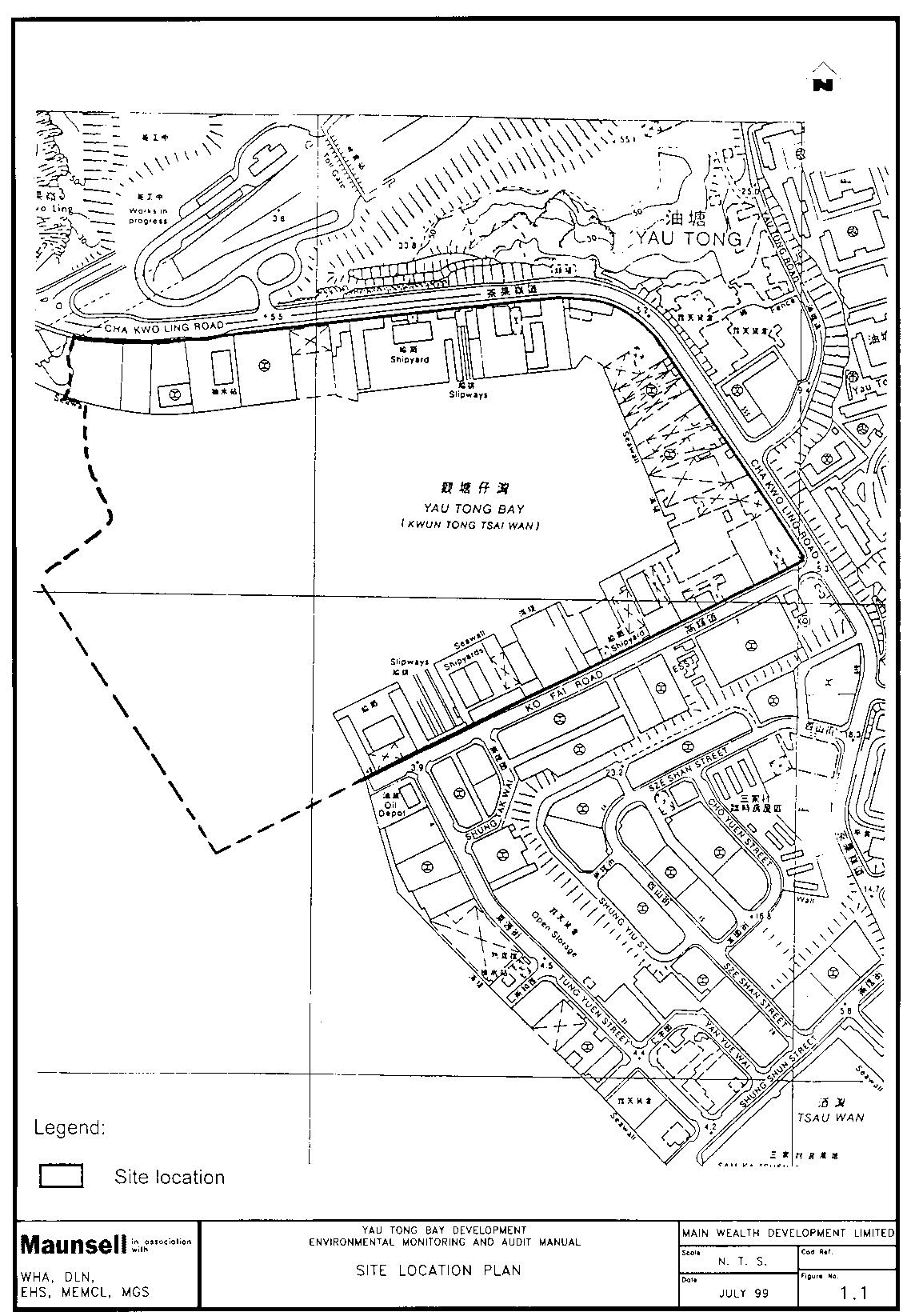
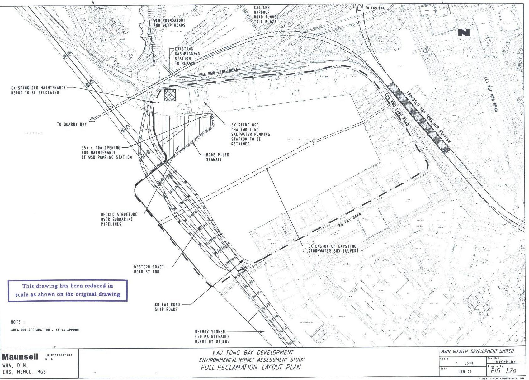
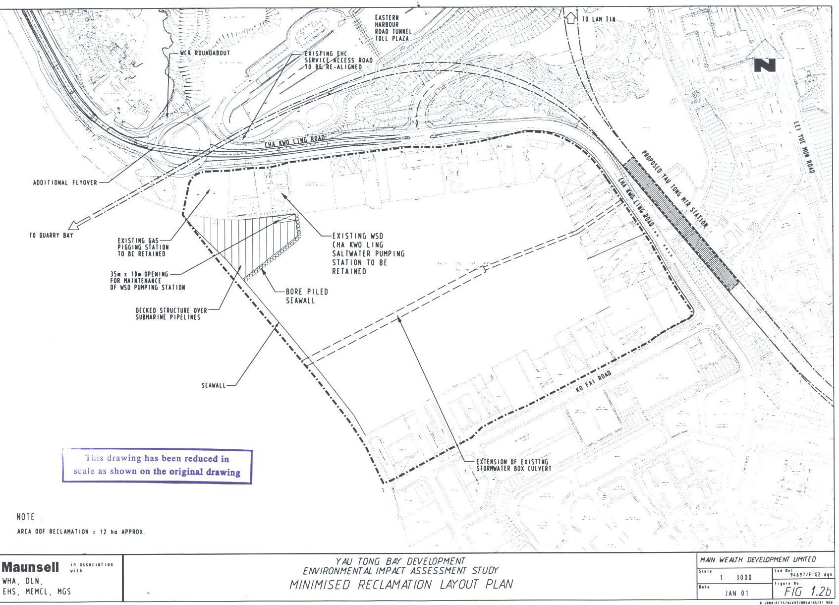
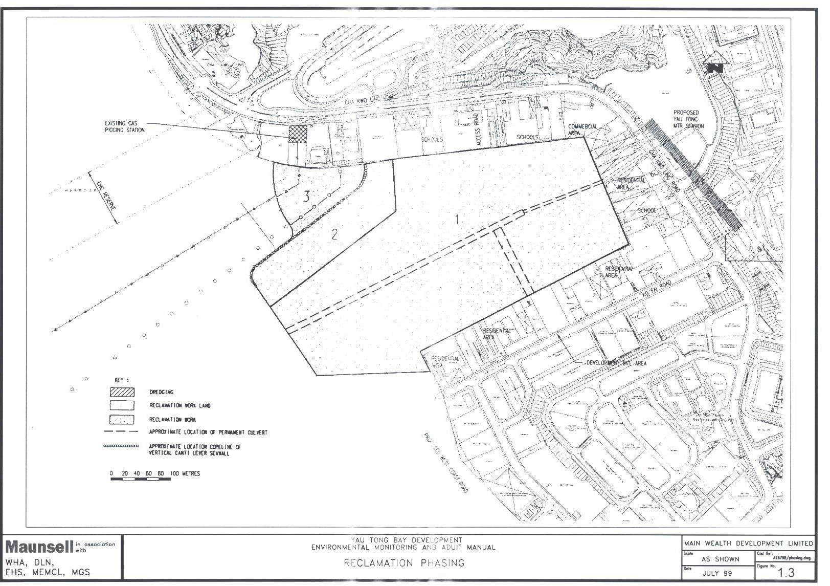
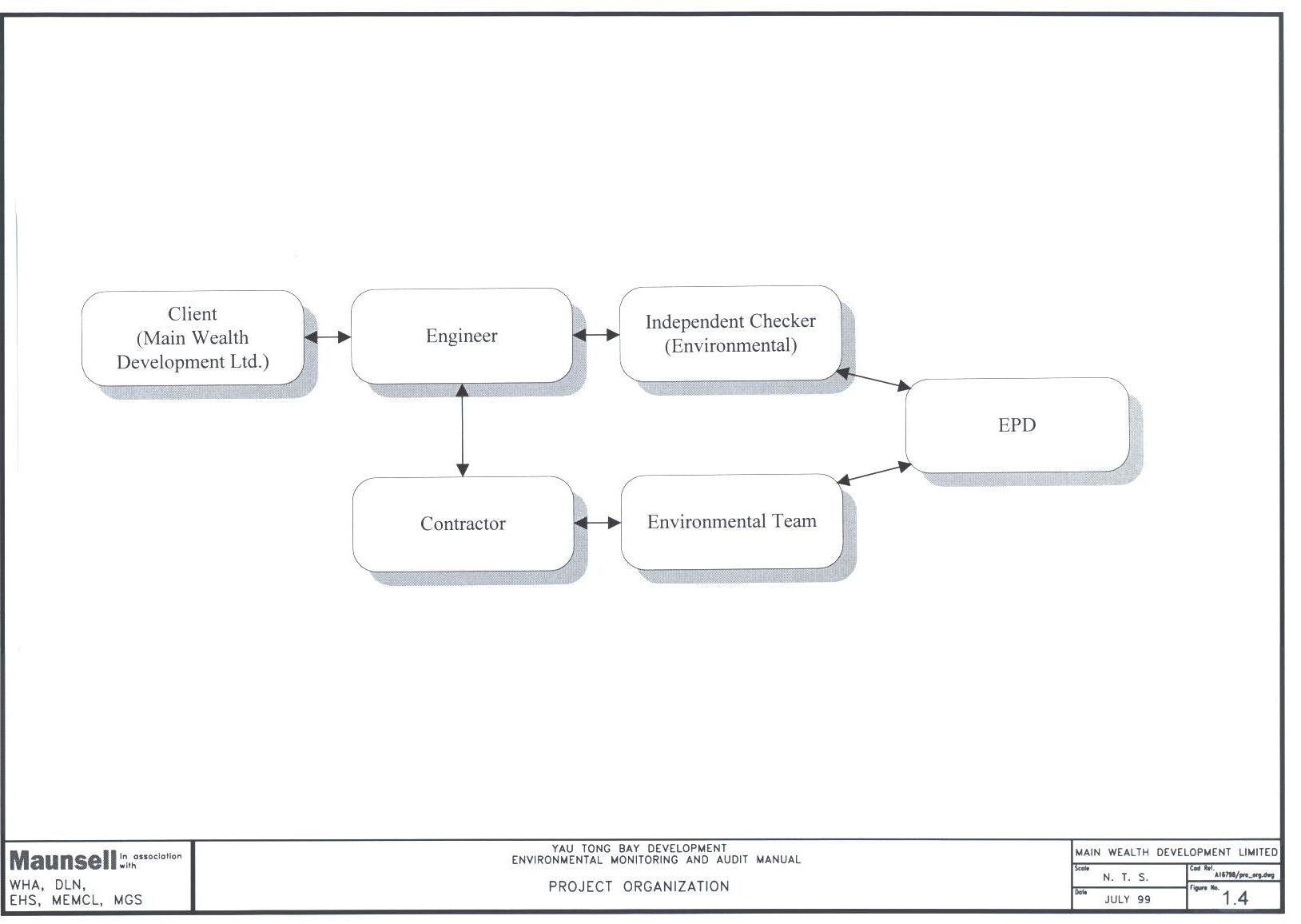
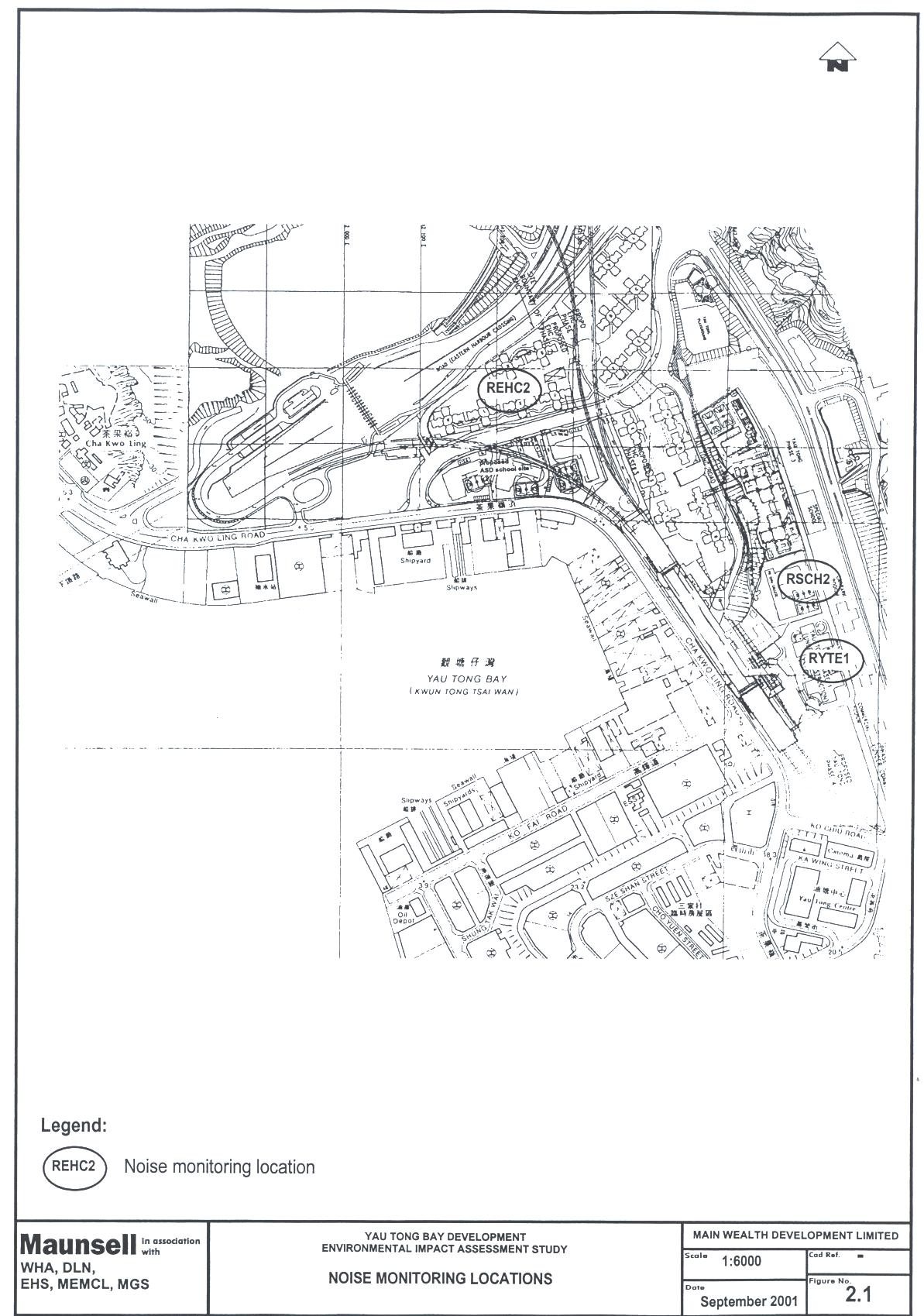
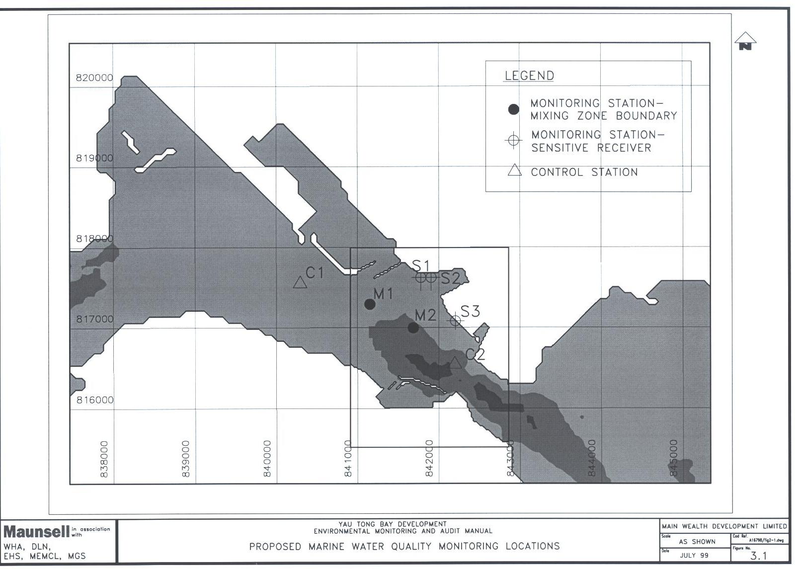
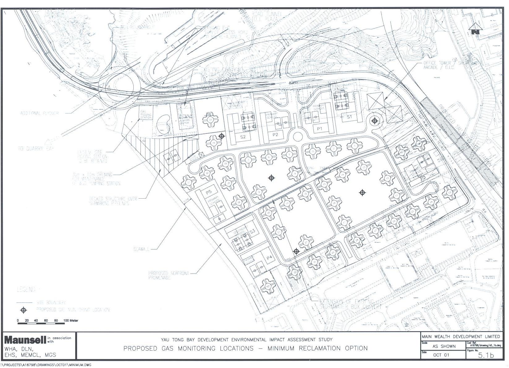