1
Detailed
Consideration of All Hazards
The hazard identification process is a
formal review to identify all hazards for the LNG facility. The hazards
identified with potential to cause loss of containment can be broadly
categorised as:
·
Internal
and process related hazards;
·
Natural
hazards;
·
External
hazards; and
·
Intentional
acts
Further elaboration of the hazards under
each category is included in the following paragraphs.
For all hazards assessed as having a
frequency of less than 10-9 per year, the frequency assessment will
be documented but no quantification of consequences will be performed.
All scenarios with a frequency greater
than 10-9 per year and potential to cause fatalities have the
consequences of the event quantified.
Hazard scenarios are excluded from the
consequence assessment if one of the following conditions is satisfied:
·
The
frequency is below 1 x 10⁻⁹ per year.
·
The
frequency of a particular event is significantly smaller than other causes of
failure considered in the generic frequency.
·
If
the generic failure frequency is judged to include events of such kind, then
such events are not assessed separately.
·
If
there are no consequences. If an event can be shown not to cause a loss of
containment then the event is not considered further.
1.1
Internal and process related hazards
1.1.1
Internal
Hazards of LNG Storage Tanks
Overfilling
The nominal capacity (i.e. usable
capacity) of the tank is 180,000 m3. The design unloading rate is
14,000 m3/hr and the unloading time is about 18 hours.
Overfilling of the inner tank may lead to
overflow into the annular space between the inner tank and the outer tank. The
bottom of the annular space is provided with 9% Ni steel up to 5m height.
Furthermore leak detectors are provided to detect any LNG leak in the annular
space bottom. Therefore, any overfilling event, if it ever occurs, can be
detected and shutdown initiated. Also, the secondary containment provided by
the outer concrete wall lined with steel will be able to contain this liquid.
There are several layers of safeguards to
prevent overfilling:
a)
The
tank to which the cargo is to be unloaded is identified before the arrival of
the carrier, its level measured and the volume of cargo to be
unloaded is pre-determined and this information is provided to the carrier. The
total volume of cargo unloaded is also continuously monitored during unloading
(typically, the volume of available space within the shore tanks is at least
equal to the cargo volume to be discharged from the carrier, i.e. ships would
not normally be required to unload cargo at multiple destinations);
b)
Continuous
level measurement on tank using four separate detection systems with at least
two different types of level measuring device; pre-alarm at normal maximum
level in tank, corresponding to the usable capacity;
c)
Level
high alarm; this is set typically with 3 to 5 minutes holding volume (between
normal maximum level and high level) at design unloading rate;
d)
High
high level initiates trip of shutdown valves in liquid inlet including transfer
piping from jetty and re-circulation lines (the trip is initiated by a 2 out of
3 voting of separate level measuring devices of different type). This will stop
further inflow of liquid into the tank. High high level trip is typically set
with about 3 to 5 minutes holding volume (between high level alarm and high
high level trip). The safety integrity level (SIL) of the high high level trip
of liquid inlet will be determined during detailed design, however, SIL 2
classification is typical for this instrumented protective system which means
that the probability of failure on demand will be less than less than 0.01;
e)
There
is further holding volume of about 10 to 15 minutes at design unloading rate
between the high high trip level and the inner suspended deck level before
liquid can overflow through the suspended deck to the annular space (it may be
noted that the actual height/volume between normal maximum level and the
overflow level is determined based on sloshing height for the safe shutdown
earthquake event; typical values are indicated above).
Based on the above, it can be seen that
there is sufficient time (more than 10 minutes) for operator intervention in
addition to the provision of high integrity instrumented protective system
(i.e. high high level trip).
Rollover
Stratification, i.e. formation of two
distinct layers of different density may occur in an LNG tank due to filling of
cargo of different density than the liquid already in the tank or due to
preferential boil-off in the tank resulting in a layer of more dense liquid at
the top (due to evaporation of lighter components) as compared to the lower
layers (where the boil-off is suppressed by the hydrostatic head but the liquid
superheats due to heat ingress and becomes warmer and less dense) [1].
Stratification may also occur due to presence of sufficient nitrogen in LNG,
typically more than 1%. Preferential boil-off of N2 results in a layer of less dense liquid
at the surface.
The phenomenon of rollover occurs when the
interface between the layers becomes unstable, leading to rapid mixing of
contents of the two layers. As the superheated liquid from the lower layer
rises to the surface, it gives off large amounts of vapour leading to potential
overpressure of the tank.
There are a number of safeguards to detect
and prevent stratification. These include:
a)
Temperature
and density gradient measurement along the tank liquid column;
b)
Provision
for circulation of tank contents through the operation of in-tank pump. Content
from tank bottom is recirculated to the top, thus releasing any superheat and
promote mixing;
c)
Provision
for filling of tank from the top or from the bottom depending on the relative
density of cargo and the tank contents;
d)
Regular
sampling and analysis of boil-off gas including monitoring of boil-off gas
quantity.
The tank is also protected by relief
valves in the event of de-stratification leading to vapour generation. Relief
valves are sized for rollover case as per EN 1473 requirements.
Inner Tank Leak
A sketch of a typical full containment
tank is shown in Figure 1.1.
The main features of a full containment
tank are that the liquid LNG is fully contained within a self-supporting inner
9% Nickel steel, surrounded by loose perlite insulation while the vapour is
contained within a surrounding concrete outer tank (which includes the slab,
the wall and the dome, all constructed of pre-stressed concrete). The concrete
outer tank serves as secondary containment and is also capable of containing
the liquid and of controlled venting of the vapour resulting from leakage of
the inner tank, should one occur.
Figure 1.1 Typical
Structure of an LNG Storage Tank
A 9% Ni steel plate is provided as liner
along the inner surface of the outer shell at the bottom up to a height of
typically 5m from the base. This protects the lower wall section of the outer
tank, mainly the wall to base slab connection in the event of leakage.
A carbon steel plate lining is provided along
the inner surface of the outer shell and roof (above the bottom Ni plate liner)
to act as vapour barrier (i.e. to prevent vapour leakage through the concrete
as well as to prevent moisture ingress from the outside).
The suspended deck is constructed of
aluminium plates and is supported by suspension rods of stainless steel from
the outer tank. Openings are provided on the suspended deck for vapour
communication between the inner tank and the outer tank so as to ensure
equilibrium of gas pressure on both sides. Insulation is provided over the deck
to minimise heat leak from the outer shell to the liquid surface.
There are no penetrations through the
outer wall or the inner tank shell. All piping to the inner tank is routed
through the tank roof.
The tank will be constructed in accordance
with BS 7777 [2].
For the capacity of tanks considered for
this project, the concrete outer shell is typically about 0.8m thick and can
withstand impact loading from projectiles.
In the case of a slab on the ground,
installing an electrical heating system in the concrete base slab prevents the
freezing of the base slab and the frost heave propagation in the ground beneath
the foundation. Heating system control and monitoring is provided.
There are a number of design features to
virtually eliminate any leakage from the full containment tank to the
atmosphere:
a)
Because
all piping is routed through the tank roof, there are no through penetrations
in the outer shell or the inner tank. Therefore the potential for any
connection failure leading to complete loss of tank inventory is eliminated;
b)
Outer
tank (of pre-stressed concrete) is designed to hold the cold LNG liquid;
c)
Inner
tank is constructed of low carbon 9% Nickel alloy steel which is heat treated.
The plate thickness varies from about 10mm at the top to about 30mm to 40mm
thick at the bottom. The material remains ductile and crack resistant at
cryogenic temperatures and is also of high strength and toughness. This
material is not subject to brittle failure when exposed to cold temperature.
d)
Tests
performed on 9% Ni steel plates and welded assemblies show good performance
against fatigue [3];
e)
In
the event of any leakage from the inner tank due to crack in the weld or other
defect, the leakage rate will remain small. The liquid will be contained in the
annular space. Leak detectors in the form of thermocouples are provided along
the annular space to detect leakage. Operator intervention is possible to empty
the tank contents and isolate the tank for inspection and repair. Liquid leakage
into the annular space is likely to result in additional vapour generation due
to contact with warmer surfaces including the perlite insulation. The relief
valves sized for the rollover case will be able to handle vapours resulting
from liquid leakage into the annular space in the event of a crack on the inner
tank;
f)
A 5m
high 9% Ni plate at the lower wall section of the outer tank prevents any
damage to the base slab to wall connection due to liquid leakage.
The engineering, construction, commissioning,
and operation procedures for the inner tank have been developed to ensure the
highest level of safety and reliability of the tank systems. For example, there
are stringent QA/QC procedures specified for material qualification and welding
qualification, material tracing and stamping, staggered vertical welds in
construction, commissioning check, etc. Such measures and procedures when
executed by highly experienced and competent contractors would virtually
eliminate the occurrence of gross human errors in material specification and
qualifications.
The long term LNG operation experience has
demonstrated that there has been no reported loss of containment incidents
involving full containment tanks.
It is also noted here that the full
containment tank design offers significant improvements over single containment
and double containment tank designs which have been prevalent earlier. More
than 70 to 80% of the aboveground tanks currently in service are either single
containment or double containment tanks.
Overpressure
The LNG tank is normally operated between
50 to 250mbarg. The tank is designed for a maximum pressure of 290mbarg.
Overpressure in tank may be caused by
several factors:
a)
Normal
boil-off due to heat leak from ambient;
b)
Vapour
displacement during filling operation;
c)
Variation
in atmospheric pressure (i.e. drop in atmospheric pressure);
d)
Flashing
of incoming liquid if it is at a higher temperature than the bubble point of
liquid at tank pressure.
Overpressure can result in failure of the
tank secondary containment. However, there are a number of safeguards provided
against overpressure:
a)
Normal
boil-off vapours from the tank is routed to a boil-off compressor where the
vapour is compressed and sent for re-liquefaction in the recondenser using the
cold liquid pump-out from the tank;
b)
Vapour
generated due to displacement during tank filling is returned to the ship
through a blower (to provide the required head for transfer) or compressed by a
separate high pressure compressor and routed to the sendout gas header;
c)
The
tank pressure is continuously monitored by two sets of pressure measurements;
d)
A
pressure control valve is provided on the tank to route all the excess tank
vapours to a vent stack. The vent stack height and tip will be determined such
that vapours discharged will disperse safely or if ignited, the radiation on
the equipment and buildings adjoining the stack are within permissible limits
as per EN 1473. The pressure control valve relieving to stack is typically
designed for all overpressure cases under normal operations (the maximum case
is typically the ship unloading case);
e)
An
independent high high pressure trip is provided which will initiate shutdown of
unloading operations (to stop liquid inflow);
f)
Relief
valves are provided on the tanks which are sized for all the cases of
overpressure. The maximum case is typically the ship unloading case for normal
operations. The governing case for relief valve is however, the rollover case,
which is an emergency case. The relief valve discharge is routed to the stack.
Underpressure
The LNG tank is normally operated between
50 to 250mbarg. The tank is designed for a minimum pressure of typically
-5mbarg.
Underpressure may be caused by several
factors:
a)
Pump-out
of liquid;
b)
Increased
compressor suction due to control malfunction;
c)
Variation
in atmospheric pressure (i.e. rise in atmospheric pressure).
Under normal operating conditions, the
boil-off generated due to heat leak is sufficient to prevent under pressure
condition. Underpressure or vacuum conditions below –5mbarg due to control
malfunction can cause failure of the tank containment. The tank bottom may be
sensitive to vacuum and could get lifted upwards.
There are a number of safeguards in place:
a) Continuous monitoring of tank pressure by
two sets of pressure measurement;
b) Low pressure alarm;
c) Low-low pressure will trip the boil-off
gas compressors and in-tank pumps and thus prevent further fall in tank
pressure;
d) Pressure control valve provided to inject
external gas from the sendout gas header into the tank;
e) Vacuum relief valves are provided which
are typically sized for maximum vapour flow arising from compressors and pumps
in operation. The operation of vacuum relief will lead to air-ingress into the
tank and thereby avoid collapse of the tank. The operation of vacuum relief is
envisaged as a measure of last resort.
1.1.2
Other
Tank Related Hazards
Failure of Foundation/Ice Heave
Ice heave could occur in the event of a
failure of the base slab heating system over a long period. This may lead to a
crack in the base slab leading to failure of the tank base.
The base slab heating is controlled by
temperature sensors. Furthermore redundant heaters with automatic switchover
and redundant power supply source are provided. Provision is also made to
replace the heaters if required while the tank is in service. Even if the
heaters were to fail, it will be long time before the ground would freeze
leading to potential failure due to ice heave. Operator intervention is
possible.
Material Defect/Structural
Defect/Construction Defect
Material defect may occur due to wrong
materials being used in tank construction. Construction defect may result in
poor welding. Structural failure of the concrete outer tank may occur, again
due to poor construction or design.
In all of the above cases, quality control
procedures including testing requirements during the design and construction
and monitoring during operation are the main means to mitigate the hazard.
The design code EN 1473 [4] outlines a
number of procedures including the following:
a)
Monitoring
of concrete, every quarter of the concrete wall or every 5,000m3 of concrete;
b)
Testing
of concrete outer wall by air pressure up to 125% of design;
c)
Hydrostatic
test of the inner tank.
Additional precautions against failure at
low temperature include gradual cooling of the tank at a rate of 50°C/hr and
gradual introduction of liquid with sufficient waiting period at different
levels to monitor any leakage.
Maintenance of In-Tank Pump/Dropped Object
In-tank pumps are provided to pump-out
liquid from the tank. This eliminates the need for nozzle penetrations through
the tank shell. Maintenance of the in-tank pump will require the lifting of the
pump from the tank bottom through the pump well to the tank roof. It is then
carried from the tank roof to the ground level for transport to the maintenance
workshop. The removal of the pump is undertaken while the tank is in service.
The liquid in the pump well is displaced by nitrogen and the pump is then
lifted from its position at which point the foot valve (at the bottom of the
well, which normally remains in open position due to the weight of the pump)
gets closed. This prevents liquid entry into the pump well during the lifting
operation.
The main hazard during this operation
arises from accidental drop of the pump (which weights about 2 tonnes) due to
failure of the sling. This may cause damage to the inner tank base plate
leading to potential leakage from the inner tank. It is unlikely to cause
damage to the concrete base. This hazard can be mitigated by appropriate
lifting procedures, including the use of dual hoist. Any leakage from the inner
tank will be contained by the outer tank.
1.1.3
Tank
Failure Frequency
The usual approach to estimating failure
frequencies is to use historical databases of failures of similar facilities.
However, there have been no failures of full containment LNG storage tanks to
date. Also, the experience is limited to about 5000 tank-years. The available
data are therefore insufficient to make statistical estimates of the failure
frequencies. The approach in the literature has been to base an assessment on
more generic data such as that from single containment tanks and then apply
reduction factors and expert judgement to take credit for the additional
protection offered by a full containment tank. The Purple Book [5] takes
such an approach to derive a frequency for catastrophic release from a full
containment tank as 1 x 10⁻⁸ per tank-year.
Other studies [6-12] into the failure
frequency of single and double containment tanks provide numbers similar to the
Purple Book. From these studies it becomes clear that the generic frequency
data for ‘catastrophic’ failures, on which the Purple Book analysis is based,
includes any failure exceeding the ‘large leak’ definition, which is about a
50mm hole. The catastrophic failure frequency of 10-8 per tank-year
for full containment tanks should therefore be interpreted as inclusive of not
only complete instantaneous tank failures but also large leaks.
This is consistent with comments in the
Purple Book to the effect that all catastrophic ruptures leading to a release
to the atmosphere are partly (50%) modelled as instantaneous release and partly
(50%) as a continuous release within 10 minutes.
Based on this, a failure frequency of 1x10⁻⁸
per tank-year was adopted in the current study. The terminal may eventually
have 3 LNG storage tanks and so the failure frequency was taken to be 3 x 10⁻⁸
per year.
This failure frequency includes all the
causes discussed above, namely embrittlement, overfilling, rollover,
overpressure, underpressure, ice heave, material/construction defects and
maintenance hazards. It is also common practice [13] to take this frequency as
inclusive of natural hazards since the generic failure frequencies calculated
in the literature include failures caused by natural events such as earthquakes
etc.
1.1.4
Internal
and Process Hazards for Piping and Equipment
The failure rate of the process areas and
piping are well documented and the values used are given in Annex 13A6.
1.2.1
Seismic
Hazard
GEO
studies conducted in the last decades indicate that Hong Kong SAR is a region of
low seismicity (e.g., GCO, 1991 [14]; GEO, 2002-2004 [15]). The seismicity in
the vicinity of Hong Kong is considered similar to that of areas of Central
Europe and the Eastern areas of the
For
this project, the full containment LNG tanks will be designed per the European
Standard EN 1473 (1997) [4] and British Standard BS 7777(1993) [2]. These
documents specifically exclude catastrophic failure of full containment tanks
designed, fabricated, erected, inspected, and tested in accordance with the
requirements contained in the codes. EN 1473 lists scenarios to be considered
in the required Quantitative Risk Assessment (QRA) and states that “no collapse
is considered for these tank types”.
In
terms of seismic risk category, LNG facilities are “essential/hazardous
facilities”, rather than “safety critical facilities” such as nuclear related
structures. Hazardous facilities are those that contain large quantities of
hazardous materials, but the release of those materials would be contained
within the boundaries of the facilities and the impact to the public would be
minimal.
For
seismic design in the LNG industry, a two-tier design approach is stipulated,
within the same framework of the risk category seismic design philosophy used
for nuclear facilities [17]. The Operating Basis Earthquake (OBE) is the
maximum earthquake for which the structure sustains no permanent damage and
restart and safe operation can resume after the earthquake. The OBE event has a
return period of 475 years. The Safe Shutdown Earthquake (SSE) is the maximum
earthquake for which the structures may sustain some permanent damage, but
there is no loss of overall structural integrity and containment of contents.
The SSE event has a return period of 10,000 years, which is the same as that
stipulated for the highest class nuclear facilities (Class 5). In addition, the
prescribed seismic design criteria for LNG tanks includes a load case for an
event less frequent than the SSE basis failing the inner tank followed by an
operating basis earthquake (OBE) aftershock acting on the outer tank. The
potential failure of the tank due to this event is not expected to occur in
The
full containment LNG tanks for this project will be founded on competent rock or
densely piled foundation. Studies conducted by LNG tank manufacturers and
constructors (e.g., Technigaz, 2003 [18]) have demonstrated that the full
containment tank of similar capacity to that proposed for this project and
designed by following EN 1473 and BS 7777 standards has the capacity to
maintain its structural and containment integrity for seismic design motions as
stipulated in Eurocode 8 [19] having up to 2.6g of peak ground acceleration
(PGA) for a rock site. This level of design earthquake motions on the bed rock
far exceeds the worst earthquake event ever recorded on a rock outcrop site
anywhere in the world. The SSE having a return period of 10,000 years
corresponds to PGA of about 0.5g based on latest seismic hazard studies
conducted for
It
is noted that a review of the earthquake resistance of LNG tanks to seismic
demand was carried out in Japan by a national examination committee following a
powerful earthquake with a PGA of 0.8g in southern Hyogo prefecture in 1995
[20]. The review concluded that the currently implemented standards are
sufficient to maintain structural integrity of LNG tanks and prevent gas leaks
even in an extremely rare and powerful earthquake. Note that an earthquake with
a PGA of 0.8g is well within the seismic design capacity for the LNG tanks in
this project which will be built to EN 1473 and BS 7777.
In consideration of the seismic design
requirements and the capacity and reliability of LNG tanks to resist seismic
demand, it is concluded that the proposed full-containment LNG tanks will
maintain structural integrity in the
1.2.2
Subsidence
Excessive
subsidence or differential settlement of ground may lead to failure of the
structures and ultimately potential loss of containment. This hazard is
relevant to facilities built on reclamation land or poor ground without proper
treatment or proper foundation design. For the
Most processing facilities at
Based on the above, the foundation design
and piping system design address the potential hazard of excessive subsidence
and differential settlement of foundation. There is therefore no basis to
presume that the facility will be more prone to subsidence than other
facilities in the world and hence the generic failure frequencies will cover
scenarios involving subsidence.
1.2.3
Lightning
Lightning strike can ignite flammable
vapour discharges from vents and stacks. Lightning strike has been the one of
the causes of petroleum tank fires. However, this is applicable to cone roof
tanks and floating roof tanks. In the case of cone roof tanks, the tank vent is
in direct communication with the atmosphere. Breath-in and breath-out occurs
during withdrawal of liquid from tank and during filling respectively. Vapours
in flammable concentration may be generated which upon ignition at the vent tip
due to lightning strike can flashback to the liquid inside (flame arrestor
provided at the vent prevents such flame flashback). In the case of floating roof
tanks, vapours generated due to seal leaks may get ignited.
The above scenarios are not applicable to
an LNG tank, which is a dome roof tank and is maintained under pressure of
about 50 to 250mbarg. A lightning strike would have no impact on an LNG tank.
1.2.4
Landslides
At the site there is up to 10m of
colluvium and weathered rock material over competent rock. The colluvium is up
to 2m thick and there are also occasional large boulders.
The excavations made to create
the tank platforms will give rise to soil slopes at the upper part with a
steeper rock slope below. Any boulders above these slopes will either be
removed or secured to the slopes. The soil slopes created by the excavation
will be secured by way of soil nails in accordance with
Failure of the soil slopes will
have no impact on the LNG storage tanks. The external concrete tank
construction can readily withstand the impact of a soil flow material without
any compromise to the containment function of the tank.
The risk of failure of the
underlying rock slopes is negligible. Rock slopes are at their most dangerous
during construction. This is because the exact nature of the state of the rock
strength and fissure patterns cannot be discerned with confidence until after
the excavation is completed. During the excavation however the rock can be
logged and fracture planes readily identified and any possible failure mode
treated by mechanical support. The possibility of future adverse water
conditions within the rock will also be controlled by drainage measures
installed during excavation. The degradation of the rock surface with time is
extremely slow and therefore this method of construction effectively guarantees
that the rock slope will be permanently stable.
1.2.5
Hill Fires
Hill fires are
a fairly common phenomenon in
The terminal
will have onsite landscape management to avoid the presence of combustible
vegetation near the LNG storage tanks and process areas. This will prevent
offsite hill fires from spreading to onsite areas. A study by Giribone [3] shows that the stability of the
concrete storage tanks is not jeopardised by a fire scenario with an incident
heat flux of 50kW/m2 (which is higher than the maximum allowable flux of
32 kW/m2 as per the design code EN 1473) over a period of 8
hours. There is no conceivable mechanism for a hill fire to produce such
radiation fluxes given the lack of vegetation near the tanks and process areas.
1.2.6
Storm Surges and Flooding
If the LNG
storage tanks or piping become submerged under water, it is possible for
buoyancy forces to lift the pipes/tanks, causing damage and possible loss of
containment.
Flooding from
heavy rainfall is not possible due to the coastal location of the site. The
slopes of the natural terrain will channel water to the sea. The primary hazard
from typhoons is the storm surge. Winds, and to a lesser extent pressure, cause
a rise in sea level in coastal areas.. In general, storm surges are limited to
several metres unless channelling effects from the coastline exasperate the
surge. South Soko’s location to the south of
The terminal
facilities, with the storage tanks located 6m above sea level and process areas
10, above sea level, are therefore protected against any risk from storm
surges, waves and other causes of flooding.
1.2.7
Tsunami
Similar to
storm surges, the main hazard from tsunamis is the rise in sea level and
possible floatation of piping and tanks. The highest rise in sea level ever
recorded in Hong Kong due to a tsunami was 0.3m high [28], and occurred as a
result of the 1960 earthquake in Chile, the largest earthquake ever recorded in
history at magnitude 9.5 on the Richter scale. With tanks and equipment
positioned 6-10m above sea level, the effect of a tsunami on the terminal is
considered negligible.
The reason for
the low impact of tsunamis on Hong Kong may be explained by the extended
continental shelf in the South China Sea which effectively dissipates the
energy of a tsunami, and also the presence of the Philippine Islands and
Seismic
activity with the
The terminal
has been designed with due consideration of sea levels, tsunamis, waves and
even rising sea levels from global warming. Being located 6-10 mPD, the
terminal is protected against all causes of flooding.
1.2.8
Summary
of Natural Hazards
The terminal site and design of the
facility are such that there will be no special risks from natural hazards.
Natural hazards are therefore not treated separately in the analysis but are
included in the generic failure frequencies (Annex 13A6).
1.3.1
Aircraft
Crash
The
Figure 1.2 Flight Paths at
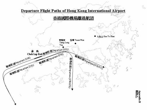
The frequency of aircraft crash was
estimated using the methodology of the HSE [21]. The model takes into account
specific factors such as the target area of the proposed hazard site and its
longitudinal (x) and perpendicular (y) distances from the runway threshold (Figure 1.3). The crash frequency per
unit ground area (per km2) is calculated as:
![]() (1)
(1)
Where N
is the number of runway movements per year and R is the probability of an accident per movement (landing or
take-off). F(x,y) gives the spatial
distribution of crashes and is given by:
Landings
 (2)
(2)
for ![]() km
km
Take-off
![]() (3)
(3)
for ![]() km
km
Equations
2 and 3 are valid only for the specified range
of x values. If x lies outside this range, the impact probability is zero.
Figure 1.3 Aircraft
Crash Coordinate System
|
|
NTSB data [22] for fatal accidents in the
U.S. involving scheduled airline flights during the period 1986-2005 are given
in Table 1.1. The 10-year moving
average suggests a downward trend with recent years showing a rate of about 2 x
10-7 per flight. However, only 13.5% of accidents are associated
with the approach to landing, 15.8% are associated with take-off and 4.2% are
related to the climb phase of the flight [23]. The accident frequency for the
approach to landings hence becomes 2.7 x 10⁻⁸ per flight and for
take-off/climb 4.0x10⁻⁸ per flight. The number of flights at Chep
Lap Kok for year 2011 is conservatively estimated at 394,000 (a 50% increase
over 2005).
Table 1.1 U.S
Scheduled Airline Accident Rate [22]
|
Year |
Accident rate
per 1,000,000 flights for accidents involving fatalities |
10-year moving
average accident rate per 1,000,000 flights |
|||||||||||
|
1986 1987 1988 1989 1990 1991 1992 1993 1994 1995 1996 1997 1998 1999 2000 2001 2002 2003 2004 2005 |
0.14 0.41 0.27 1.10 0.77 0.53 0.53 0.13 0.51 0.12 0.38 0.30 0.09 0.18 0.18 0.19 0.00 0.2 0.09 0.27 |
- - - - - - - -
|
Considering landings on runway 07R for
example, the values for x and y according to Figure 1.3 are 3.2 and 13.8km respectively. Applying Equation 2 gives ![]() km-2. Substituting this into Equation 1 gives:
km-2. Substituting this into Equation 1 gives:
![]() /year/km2
/year/km2
The number of plane movements has been
divided by 8 to take into account that half of movements are take-offs and only
a quarter of landings use runway 07R. This effectively assumes that each runway
is used equally and the wind blows in each direction with equal probability.
The target area is estimated at 15,000m2
or 0.015km2 (3 tanks of 80m diameter). This gives a frequency for
crashes into the tanks associated with landings on runway 07R as 3.4 x 10⁻¹⁰
per year. Repeating the calculation for landings and take-offs from all runways
gives the results shown in Table 1.2.
Table 1.2 Aircraft
Crash Frequency onto
|
Runway |
Landing (per year) |
Take-off (per year) |
|
07R 07L 25L 25R |
3.5
x 10-10 2.6
x 10-10 0 0 |
0 0 2.6
x 10-13 5.7
x 10-14 |
|
Total |
6.1
x 10-10 |
3.2
x 10-13 |
The combined frequency of all take-off and
landing crashes onto the LNG tanks from activities on all runways is less than
1 x 10⁻⁹ per year. The hills on
1.3.2
Helicopter
Crash
Helipad Activity
The
Data from offshore helicopter activities
[24] gives a helipad related helicopter crash frequency of 2.9 x 10⁻⁶
per flight stage (i.e. per take-off and landing). However, most of these
incidents are minor such as heavy landings. For a helicopter incident to damage
the facility, it must be a serious, uncontrolled impact. Only accidents
involving fatalities were therefore considered in the analysis. 4% of incidents
resulted in one or more fatalities and so the frequency of uncontrolled crashes
was calculated as 2.9 x 10-6 x 0.04 = 1.2 x 10⁻⁷ per
flight stage. For one flight per week using the helipad, the annual crash
frequency becomes 1.2 x 10-7 x 52 = 6.0 x 10⁻⁶ /year.
Helicopter accidents during take-off and
landing are confined to a small area around the helipad [21]. 93% of accidents
occur within 100m of the helipad. The remaining 7% occur between 100 and 200m
of the helipad. There have been no serious helipad related incidents resulting
in a crash beyond 200m of the helipad.
The distance of the
![]() (4)
(4)
where r
is the LNG storage tank radius, assumed to be 40m. Combining this with the
accident frequency of 6.0 x 10⁻⁶ /year gives the frequency of a
helicopter crashing into the nearest storage tank = 2.2 x 10⁻⁸
/year.
Figure 1.4 Position
of Helipad Relative to Storage Tanks
|
|
The other LNG storage tanks and process
areas lie beyond the 200m radius and hence will not be exposed to any increased
risk from helicopter activity at the helipad.
Passing
Helicopters
Although take-off and landings present the
greatest portion of risk from a flight, South Soko lies close to the flight
path for helicopter shuttles plying between Hong Kong and Macau [25] (Figure 1.5).
Figure 1.5
The CMPT Reports [24] gives a frequency of
in-flight accidents of 1.2 x 10⁻⁵ per flying hour. However, only 17%
of these are severe enough to cause a fatality. Assuming, as before, that
incidents involving fatalities are a reasonable measure of uncontrolled crashes
that may impact a facility, then the frequency becomes 2.0 x 10⁻⁶
per flying hour.
The helicopters shuttling between Hong
Kong and
Frequency
of uncontrolled crashes =
![]() /km
/km
There are several routes indicated in Figure 1.5, depending on the weather and
flight direction either to or from
Frequency
of uncontrolled crashes ![]() /km2/year
/km2/year
The footprint area of 3 LNG storage tanks
is approximately 15,000 m2 or 0.015 km2. The frequency of
a helicopter crashing during the in-flight stage and colliding with an LNG
storage tank is therefore 3.6 x 10⁻⁷ /year. This is an order of
magnitude greater than the frequency calculated for helipad related incidents
because of the much higher traffic volume of passing helicopters.
Similarly, the footprint area of the
process areas was estimated at 10,900m2, giving a frequency of
helicopter impact of 2.6 x 10⁻⁷ /year.
The
The frequency of helicopter crashes into
the process area is small compared to the frequency of internal and process
related failures. As an example, the vaporisers occupy an area of approximately
6000m2. A crash into the vaporiser area would have a frequency of
1.4 x 10⁻⁷ per year based on the above calculations. This would
undoubtedly cause damage; however, the generic failure frequency of all
vaporisers combined is 8.5 x 10⁻⁵ per year. The additional hazard
from helicopter activities is almost 3 orders of magnitude smaller and may be
neglected with negligible difference in the risk calculations. Hazards from
helicopters are therefore not treated separately but are covered by the generic
failure frequency.
Consequence
of Helicopter Impact
There have been several studies related to
the possible impacts of aircraft collisions with hazardous facilities such as
nuclear power stations. A study by the Nuclear Energy Institute [27]
investigated the damage that could be caused by a fully loaded wide-bodied
Boeing 767 crashing at 350 mph (560 km/h) into a nuclear reactor containment
structure. These containment buildings are cylindrical shaped buildings with a
dome roof, typically 140 feet high and 140 feet diameter. They are made of
pre-stressed concrete with wall thicknesses from 3.5 to 4.5 feet. This is very
similar to the construction of LNG storage tanks, which have a concrete wall of
about 0.8m thickness. The conclusions of the report were that the concrete
containment would not fail from such an impact.
In another study [13], the consequence of
a Boeing 767 commercial aircraft crashing into an LNG storage tank was
specifically assessed. It was concluded that aircraft are constructed from
mostly soft materials and only the core of the engines is capable of
penetrating an LNG full containment tank. Further, the engine would need to
impact at near perpendicular incidence otherwise the engine will simply deflect
off the tank.
These studies demonstrate the structural
strength of the LNG storage tanks. They are designed to withstand major
impacts. Naturally, a helicopter crash is very different from a 200 tonne
airliner travelling at 560 km/h. Most helicopter crashes have an impact
velocity below 50 m/s [21]. A fully loaded 5-tonne Sikorsky S76C with an impact
velocity of 50 m/s would have a kinetic energy 390 times less than the Boeing
767 analysed by the Nuclear Energy Institute. It is concluded that a helicopter
crash will not cause a failure of the LNG storage tanks.
Summary
Helicopter crashes into the LNG storage
tanks have a small but quantifiable frequency, although the impact would not
cause a failure of the tank. LNG storage tanks are designed to withstand such
an impact and other studies in the literature suggest that the tanks could
easily cope with a helicopter crash.
A helicopter crash into the process areas
or piping (including the piping on the LNG tanks) could cause damage but the
frequency of such events is much lower than generic failure frequencies. The
additional risk from helicopter activity is negligible. Scenarios involving
helicopter activities were therefore not treated separately but are covered by
the generic failure frequency.
1.3.3
External
Fire and Explosion Hazards
The LNG tank may be exposed to radiation
and fire effects as well as explosion
overpressure effects including flying debris arising from ignition of flammable
gas leak in process units located adjoining an LNG tank or neighbouring
facilities. A study by Giribone et al [3] shows that a full containment tank
with outer concrete shell (of about 0.8m thick wall and 0.5m thick roof) can
withstand fire and flying debris impacts without any damage to the tank
containment.
The study by Giribone shows that the
stability of the concrete structure is not jeopardised by a fire scenario with
an incident heat flux of 50kW/m2 (which is higher than the maximum allowable flux of
32 kW/m2 as per the design code EN 1473) over a period of 8
hours. Although through cracks in the concrete structure may occur, the
structural integrity of the tank is not compromised.
The study by Giribone also shows that a
flying debris of 2000kg in mass (a typical 4” valve weighs no more than 125kg)
travelling at 50m/s causes no significant impact on the concrete structure,
though cracks may be created by such an impact. The abovementioned studies [13,
29] suggest that the tanks can withstand considerable greater impact.
Based on the above it can be concluded
that the outer concrete structure of a full containment tank provides
significant resistance against external fire and explosion hazards. Failure of
the tank due to such events will not occur. It may be also be noted here that
the extent of process equipment and piping is very limited in a receiving
terminal, as compared to an export terminal consisting of a liquefaction plant,
and the hazards of fire and explosion events with potential to affect the tank
is not significant. Hence external fire and explosion hazards causing damage to
the tank is considered to be negligible. In any case, the frequency of tank
failure considered in Section 1.1.3
is considered representative of all potential failure modes.
A full scope Safeguards and Security Risk Assessment (SSRA) was
conducted in
Given the sensitive and confidential nature of the analysis and in
order to protect public safety, the complete SSRA report is available only on a
need to know basis to GOHK and CAPCO security personnel.
The team who prepared the SSRA reviewed the history of terrorist
events on LNG terminal facilities and determined that there has never been a
terrorist incident at any LNG terminal or LNG carrier that has resulted in a
death or injury to a member of the public. The relative risk of a terrorist
induced injury or fatality to the public at a Hong Kong terminal was also
compared to that for other terminals around the world, including Asia, Europe
and the
The Project was benchmarked against other LNG facilities worldwide
in the
Based on the benchmarking comparison on the risk of terrorist
threats, the Project was assessed to be at a lower security risk threat level
than the other LNG terminals, indicating that the
The conclusion reached by the SSRA team was that based on the
overall low threat environment in Hong Kong and the risk analysis of the
worst-case scenario of an intentional act in nature, their recommended risk
mitigating measures would help to reduce the scenarios associated risk to a
level that is well within levels generally accepted by
industry globally, for either a Black Point or South Soko Island terminal. It was also concluded that whilst risk of a terrorist act
directed at both sites is extremely low, the consequence of a terrorist event
on the public would be greater for an incident at a Black Point terminal or
against an LNG carrier on portions of the marine transit route to Black Point
than for a South Soko terminal or its marine transit.
The SSRA team assessed the consequences that would result from the
terrorist induced scenarios evaluated. Based on the available published
studies, the team determined that the consequences of these events did not
exceed the worst case events evaluated in the Terminal and Marine QRA studies.
1.5
Low Level Radioactive Waste Facility
A low level radioactive waste
facility (LLRW) has recently been constructed on
The LLRW facility is embedded
into the rock structure of North Soko, about 1.5km from the proposed LNG
terminal site on
The facility does not contain combustible
materials, merely the steel drums placed in a room with concrete walls. A fire
detection system is installed to alert regarding a fire incident. The facility
also has fire protection systems for extinguishing fires. Material for storage
is delivered just twice a year so there is no permanent presence of people in
Potential LNG release
scenarios from the South Soko LNG terminal that could result in a flammable gas
cloud travelling to
If such a vapour cloud were then ignited downwind,
the resulting fire would flash back to the release source. Since the flame
travels through the cloud quickly, the potential to cause secondary fires at
the LLRW facility and escalate to the point where it affects the radioactive
waste stored there is very low. This is due to the enclosure of the facility in
a concrete/rock structure, absence of any combustible materials in the facility
design and the provision of a fire protection system at the LLRW facility.
Combining the probability of ignition and secondary fires with the very low LNG
release frequency of 3 x 10⁻⁸ per year will produce an outcome
frequency of well below 1 x 10⁻⁹ per year. The risks are therefore
less than 10-9 per year and this scenario was not considered further
in the analysis.
Based on a detailed review of the various
failure modes along with the safeguards provided, the failure frequency of the
full containment LNG tank is taken to be 1x10⁻⁸ per tank-year. This
failure frequency encompasses internal and process causes of failure as well as
any natural/external hazards.
External hazards to the LNG storage tanks
from aircraft were assessed to have a frequency below 1 x 10⁻⁹ per
year. Helicopter crashes have a small but quantifiable frequency but the tanks
are designed to withstand such impacts and so there would be no consequences
from such an event. Hence, failure of the storage tanks due to helicopter
impact was also excluded from the analysis.
Helicopter impacts into the piping and
process areas are a possible scenario, but the frequency of occurrence is small
compared to process risks. Helicopter crash scenarios are therefore included in
the generic frequencies.
Escalation events affecting the
radioactive waste facility on
References
[1] Baker, N., Creed, M., Stratification and
Rollover in Gas Storage Tanks, Trans IChemE, Vol. 74, Part B, 1996
[2] BS 7777: Flat-bottomed, vertical,
cylindrical storage tanks for low temperature service,
[3] Giribone, R., Claude, J., Comparative
Safety Assessment of Large LNG Storage Tanks, Eleventh International Conference
on LNG, 1995
[4] EN 1473: Installation and Equipment
for Liquefied Natural Gas – Design of onshore installations,
[5] TNO, Guidelines for Quantitative Risk Assessment
(The Purple Book), Report CPR 18E, The
[6] Rijnmond Public Authority, A Risk Analysis
of Six Potentially Hazardous Industrial Objects in the Rijnmond Area- A Pilot
Study, COVO, D. Reidel Publishing Co., Dordrecht, 1982.
[7]
[8] E&P Forum, E&P Forum QRA Datasheet
Directory, 15 October 1996.
[9] Davies, T., Harding, A.B., McKay, I.P.,
Robinson, R.G.J., Wilkinson, A., Bund Effectiveness in Preventing Escalation of
Tank Farm Fires, Trans IChem E, Vol 74, Part B, May 1996.
[10] Christensen, R.A. and Eilbert, R.F.,
Aboveground Storage Tank Survey, EL RN-623, Entropy Limited,
[11] Batstone, R.J. and
Tomi, D.T., Hazard Analysis in Planning Industrial Developments, Loss
Prevention, 13, 7, 1980.
[12] Canvey: a second report, HSE, 1991.
[13] Hazards Analysis of a Proposed LNG Import Terminal in the Port of Long Beach, California, Quest Consultants Inc., Aug 2005.
[14] GCO, Review of earthquake data for the Hong Kong region, GCO Publication No. 1/91, Civil Engineering Services Dept., Hong Kong Government, 1991
[15] GEO, Seismic hazard analysis of the
[16] Scott, D.N., Pappin, J.W., Kwok,
M.K.Y., Seismic Design of Buildings in Hong Kong, Hong Kong Institution of
Engineers, Transactions, Vol. 1, No. 2, p.37-50, 1994
[17] ASCE/SEI 43-05, Seismic design
criteria for structures, systems, and components in nuclear facilities, ASCE,
2005
[18] Personal communication on tank capacity
studies with Technigaz, 2003
[19] Eurocode 8: Design of Structures for
Earthquake Resistance, European Committee for Standardisation, 1998
[20] Mizuno, T., Wadano, Y., Terada, N.,
Tsunomura, T., Demonstrative Safety Assessment of LNG Storage Facility
Earthquake Resistance and Reinforcement of Crisis Management at LNG Receiving
Terminals, Twelfth International Conference on LNG, 1998
[21] Byrne,
J. P., The Calculation of Aircraft Crash Risk in the
[22] www.ntsb.gov/aviation/Table6.htm
[23] Annual Review
of Aircraft Accident Data: U.S. General Aviation, Calendar Year 2001, National
Transport Safety Board.
[24] Spouge, J., A guide to Quantitative Risk Assessment for Offshore Installations, CMPT, 1999.
[25] AIP Hong
Kong, Aeronautical Information Publication, Part 2, En-route, ENR 3.4
Helicopter Routes, Civil Aviation Department, Hong Kong, Feb 2004.
[26] www.helihongkong.com
[27] Aircraft
Crash Impact Analyses Demonstrate Nuclear Power Plant’s Structural Strength,
Nuclear Energy Institute, Dec 2002.
[28] www.hko.gov.hk
[29] Lee, B. Y., Report of Hong Kong in the International Tsunami
Seminar in the Western Pacific Region, International Tsunami Seminar in the
Western Pacific Region,