2
Consideration
of south soko terminal alternatives
The following section presents a
consideration of the alternatives for the South Soko terminal. The section has been divided into a
discussion of the following:
·
Consideration
of Different Layouts and Design Options;
·
Consideration
of Alternative Construction Methods;
·
Consideration
of Pipeline Alignment; and,
·
Consideration
of Power and Water Supply.
Based on the above considerations, the
Environmental Impact Assessment of the preferred South Soko terminal scenario
is presented in subsequent sections.
2.1
Consideration of Different Layouts and Design Options
In accordance with Clause 3.3.4 of the EIA Study Brief (ESB-126/2005), this section presents considerations of the different
layouts and design options that have been assessed as part of the overall
assessment of alternatives for the South Soko LNG terminal. The methodology, criteria and findings
are presented.
The assessment was conducted to
investigate the environmental considerations of each preliminary layout and
design option and to examine the engineering aspects for each. The assessment thus considers both the
difficulties of the construction and operation of each facility as well as the
associated potential environmental impacts.
2.1.1
Layout
Options
The basic requirements of a LNG receiving
terminal in Hong Kong have been described in detail in Part 1 - Section 3.
Justifications for South Soko Island being considered as one of two
sites for the LNG receiving terminal in Hong Kong have been presented in Part 1 – Section 4.
Several terminal layout options on South
Three layouts have been selected for
further assessment in order to provide a comprehensive assessment of different design
options. The layouts present a wide
range of engineering options and subsequent environmental considerations for
the construction and operation of the South
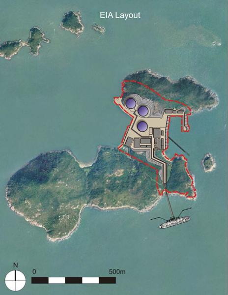
Option 1 – Base Case
The Base Case layout (Option 1) is derived
from a combination of reclamation and excavation, for the purpose of
maintaining a balance between the cut and fill quantities (Figure 2.1). The excavation on the northern side of
the site will be undertaken to provide sufficient land area, initially for two
tanks with provision for a third tank in the future. The tank excavation area is completely
within the northern hillside for two purposes:
1.
To
enable the tanks to be founded directly onto rock which will permit the use of
pad/raft foundations thus negating the need for deep foundations; and
2.
To
screen the tanks from the visually sensitive receivers on the south side of
The excavation on the southern side of the
site will be undertaken to provide sufficient land area for the process plant
and associated facilities to maintain the regulatory safe distances from the
storage tanks in accordance with EN 1473. The elevation of these facilities will
be up to +10mPD in order to reduce the volume of cutting and to provide a
raised platform to prevent wave overtopping to the process area.
Land will be reclaimed immediately to the
west of the former detention centre for the proposed utility pier, and to the
east of the platform for the proposed service jetties.
The LNG carrier jetty will be located at
the northwestern side of
Option 2 – Full Reclamation
The Full Reclamation layout (Option 2) was
considered to reduce the amount of land excavation by increasing the area of
reclamation within the
Area will be reclaimed within the
As in Option 1 the LNG carrier jetty will
be located at the northwestern side of
Option 3 – South East Jetty
The basic plan of the South East (SE)
Jetty layout (Option 3) is also similar to Option 1 with the three tanks
located within the north side of the site (Figure 2.3). The excavation on the southern side of
the site will be undertaken to a platform of up to +10mPD to house the process
plant and associated facilities.
The location of the jetty in Option 3 is
revised to suit the ‘no reclamation’ layout as the design distance requirement
between the berthing head and the process area/storage tanks may be satisfied
with a shorter trestle. The jetty
is therefore moved closer to the shore.
The estimated land area required is slightly larger than in Options 1
and 2 and is measured to be 38.6 ha.
A small amount of land will be reclaimed immediately to the west of the
existing platform for the proposed utility pier, and to the east of the
platform for the proposed service jetties.
The main difference between this option
and the above two options is that the LNG carrier jetty will be located at the
southeastern side of
Engineering Works Criteria
In order to satisfy each of the terminal
requirements described in Part 1 -
Section 3, it is necessary to undertake site formation, dredging and
reclamation works at each of the layout options at
Table 2.1 Summary
of Engineering Works Criteria (based on conceptual indicative site layouts –
numbers are approximate)
|
Engineering Criteria |
Option 1 (Base Case) |
Option 2 (Full Reclamation) |
Option 3 (SE Jetty) |
|
Site Area
(ha) |
29 |
35 |
38.6 |
|
Volume of
Dredging for Reclamation at |
0.18 |
0.22 |
0.18 |
|
Volume of
Dredging for |
3.36 |
3.36 |
1.07 |
|
Volume of
Dredging for Submarine Gas Pipeline (106m³) |
1.44 |
1.44 |
1.44 |
|
Volume of
Excavation Disposed (106m³) |
0.04 |
0 |
0.12 |
|
Volume of
Fill Imported (106m³) |
0.28 |
1.26 |
0.14 |
|
Size of Reclamation
(hs) |
1.7 |
13 |
1.7 |
|
Length of
Natural Coastline Affected (m) |
450 |
600 |
450 |
|
Length of
Seawall (m) |
1,100 |
1,360 |
1,100 |
|
Seawall
modification (ha) |
1.3 |
0.5 |
1.3 |
|
Length of
Trestle (m) |
200 |
200 |
240 |
The layouts described above have been
assessed and compared in terms of the engineering works required and the
potential for environmental impacts through construction and operation. Each of these assessments is presented
below and the findings combined to determine preferred overall site layout.
2.1.2
Engineering
Assessment
Overall Engineering
Assessment Criteria
A set of key engineering assessment
criteria have been established to enable a quantitative comparison of the three
layout options to be scored and ranked in accordance with their relative merits
and demerits. As each of the
assessment criteria do not have an equivalent impact on the overall
construction of the terminal facility, a relative importance factor has been
applied to each as shown in Table 2.2.
Table 2.2 Overall
Engineering Assessment Criteria & Associated Relative Importance Factors
|
Engineering Assessment Criterion |
Relative Importance Factor |
|
Construction
of site formation works |
0.30 |
|
Construction
of site reclamation works |
0.30 |
|
Construction
of approach channel and turning basin |
0.20 |
|
Marine
navigation |
0.10 |
|
Construction
of facility foundations |
0.10 |
|
Total |
1.00 |
The rationale for the relative importance factor
is given below.
·
It
was considered logical for the sum of the relative importance factors to add up
to unity. In this manner each
relative importance factor also directly represents the percentage importance
to the whole process.
·
The
major engineering works for each of the layout options is considered to be the
construction of the site formation and reclamation. These assessment criterions are
therefore given an equally high relative importance factor of 30% each.
·
The
next major engineering works for the layout options is the construction of the
approach channel and turning basin.
This assessment criterion is therefore assigned a reasonable importance
factor of 20%.
·
·
The
construction of the facility foundations and the receiving terminal facility
itself will generally employ conventional construction techniques which will be
similar to all sites with only minor differences resulting from accessibility
and specific location constraints.
A relatively low weighting of 10% is therefore applied for these
criteria.
Parameters for Each Engineering Assessment
Criterion
In order to make a quantitative assessment
of the relative advantages and disadvantages of each layout for each of the
engineering assessment criterion defined in Table
2.2, a set of engineering parameters reflecting the main tasks to be
undertaken under each activity have been developed. Each parameter carries a weighting to
represent the relative significance and impact on the overall engineering
assessment criterion. It was
considered logical for the sum of the relative weighting factors to add up to
unity. In this manner each relative
weighting also directly represents the percentage importance to the whole
process. The parameters used in the
evaluation of the sites for each engineering assessment criterion is detailed
in Tables 2.3 to 2.7 and described below.
Construction of Site
Formation Works
The engineering assessment criterion for
site formation considers nine main parameters as shown in Table 2.3.
Table 2.3 Engineering
Parameters and Associated Relative Used for the Assessment of the Construction
of Site Formation Works
|
Engineering Assessment Criterion |
Parameter |
Relative Weighting |
|
Construction
of site formation works |
Volume of
excavation in soil |
0.05 |
|
Volume of
excavation in rock |
0.25 |
|
|
Volume of
soil to be disposed of |
0.20 |
|
|
Volume of
rock to be disposed of |
0.05 |
|
|
Impact on
construction programme |
0.10 |
|
|
Slope
stabilisation measures required |
0.10 |
|
|
Slope
maintenance |
0.05 |
|
|
Future
slope hazard |
0.05 |
|
|
Blasting
risks |
0.15 |
|
|
Total |
1.00 |
The rationale for the selection of each
relative weighting factor is given below
·
The
most difficult and time consuming activity is usually the excavation of rock
material, which generally comprises very good quality granite. The excavation of this material will
require significant effort using blasting and heavy mechanical equipment for
which stringent engineering controls will be required. The excavation works are also generally
intimately linked with the commencement of construction of the storage tanks,
which have a long construction duration and are therefore critical path
activities. As such the rock
excavation has a significant impact on the construction programme. The highest weighting of 25% is
therefore assigned to this parameter.
·
The excavation
of soil is a relatively easy and quick task utilising mechanical equipment and
therefore only a low weighting of 5% is assigned. The volume of soil excavation is also
generally small.
·
The
disposal of the soil material is given a high weighting of 20% as it will need
to be taken to one of the Public Fill facilities, which should be avoided to
the extent practicable or possible.
High scores are therefore awarded to sites which limit disposal of soil and
make the best use of the material.
·
The
disposal of rock is given a low weighting of 5%, as it will likely be reused
for construction in
·
The
construction period for the terminal facility needs to be minimised to meet the
required project operational target date.
As the site formation works impact directly on the construction
programme, a medium weighting factor of 10% is considered appropriate to favour
the sites that can be constructed in the shortest duration.
·
Blasting
will need to comply with extensive and stringent regulation requirements. Incorporation of these measures will
impact on the construction programme; and therefore, a medium level relative
weighting of 15% is applied to these works to favour the sites that do not
require blasting.
·
The
slope stabilisation works associated with the facility will need to comply with
the regulation requirements which are reasonably stringent and can be extensive
for large slopes. The quantity of
stabilisation works therefore needs to be reduced as far as possible. A medium relative weighting factor of
10% is applied to these works.
·
Slope
maintenance and slope hazards are both events that will be under the control of
the LNG terminal facility during operation. These can therefore be reasonably
managed and as such a low weighting of 5% has been assigned to each.
Construction of Site Reclamation Works
The engineering assessment criterion for
reclamation considers ten main parameters as shown in Table 2.4.
Table 2.4 Engineering
Parameters and Associated Relative Used for the Assessment of the Construction
of Site Reclamation Works
|
Engineering Assessment Criterion |
Parameter |
Relative Weighting |
|
Construction
of site reclamation works |
Area of
reclamation |
0.10 |
|
Volume of
dredging material |
0.20 |
|
|
Total
volume of fill material required |
0.05 |
|
|
Total volume
of imported fill (sand + rock) |
0.20 |
|
|
Length of
natural coastline affected |
0.15 |
|
|
Length of
artificial coastline affected |
0.05 |
|
|
Length of
seawall required |
0.10 |
|
|
Construction
time for dredging and filling |
0.05 |
|
|
Time for consolidation
after construction |
0.05 |
|
|
Need for
ground improvement |
0.05 |
|
|
Total |
1.00 |
The rationale for the selection of each
relative weighting factor is given below.
·
The most
significant activities are the dredging of the underlying soft material and the
importation requirements for subsequent back filling works. For the latter case a lower amount of
imported material is considered more favourable as it indicates that a better
balance is being made with the excavated materials from the site formation
works. A high weighting of 20% is
therefore assigned to these parameters.
·
As
the volume of imported material has already been considered, the total volume
of fill material required is less important if the majority is sourced from
within the site and therefore only a 5% weighting is assigned.
·
The
length of natural coastline affected by the reclamation is a measure of the
extent of the engineering works on the natural site areas. A 15% weighting is therefore assigned to
this parameter.
·
The
length of artificial coastline affected by the reclamation is considered to be
less of an effect and therefore a 5% weighting is applied.
·
The
length of seawall and the area of reclamation are indicators of the extent of
the reclamation. For these
parameters a medium weighting of 10% is deemed appropriate.
·
The
time for construction, time for consolidation and the need for ground
improvement are important but less significant engineering issues. A lower weighting of 5% is therefore
assumed for these parameters.
Construction of Approach Channel and
The engineering assessment
criterion for the construction of the approach channel and turning basin
considers five main parameters as shown in Table 2.5.
Table 2.5 Engineering
Parameters and Associated Relative Used for the Assessment of the Construction
of Approach Channel and
|
Engineering Assessment Criterion |
Parameter |
Relative Weighting |
|
Construction
of approach channel and turning basin |
Total
length of approach channel + turning basin |
0.20 |
|
Volume of
dredging |
0.35 |
|
|
Rock
excavation in dredged zone |
0.20 |
|
|
Impact on
existing utilities |
0.15 |
|
|
Siltation
& maintenance dredging |
0.10 |
|
|
Total |
1.00 |
The rationale for the selection of each
relative weighting factor is given below.
(i) For approach channel and
turning basin the most significant activity is the dredging works. A high weighting of 35% is therefore
assigned to this parameter.
(ii)
The length of the approach channel and the
extent of rock excavation will affects the programme and progress of the
overall dredging works and are therefore each assigned a high to medium weighting
of 20%.
(iii)
The impact on existing utilities is
considered to be localised and secondary effects on the overall dredging works
and is therefore assigned a medium weighting of 15%.
(iv)
The
siltation/maintenance for the approach channels are factors that affects the
long-term operation for which a low to medium weighting of 10% is considered
appropriate.
Marine Navigation
The engineering assessment criterion for
marine navigation considers four main parameters as shown in Table 2.6.
Table 2.6 Engineering
Parameters and Associated Relative Weighting Used for the Assessment of Marine
Navigation
|
Engineering Assessment Criterion |
Parameter |
Relative Weighting |
|
Marine
navigation |
Marine
traffic |
0.50 |
|
Grounding
potential |
0.10 |
|
|
Striking
berth by LNG Carrier |
0.10 |
|
|
Striking
of the moored carrier by passing traffic |
0.30 |
|
|
Total |
1.00 |
The rationale for the selection of each
relative weighting factor is given below:
· Although historically, LNG carriers have had an
excellent safety record, the main hazards are the potential for collision with
the carrier while in transit to the jetty or from passing traffic striking the
carrier while moored. The
probability for such occurrences and consequences will be dependent upon
traffic density and discipline of shipboard personnel complying with underway
regulations. As these are the
main considerations a weighting of 0.5 and 0.3 are awarded for marine traffic
and the striking of the moored carrier by passing traffic respectively
·
The
consequence of grounding and striking of the marine berth is significantly
lower than the above considerations, therefore, a lower but equal weighting of
10% is assigned to each.
Construction of Facility Foundations
The Engineering assessment criterion for
construction of facility foundations considers three main parameters as shown
in Table 2.7 below.
Table 2.7 Engineering
Parameters and Associated Relative Weighting Used for the Assessment of the
Construction of Facility Foundation
|
Engineering Assessment Criterion |
Parameter |
Relative Weighting |
|
Construction
of facility foundations |
Terminal
facility structures |
0.30 |
|
Jetty
piling works |
0.50 |
|
|
Water front
access |
0.20 |
|
|
Total |
1.00 |
The rationale for the selection of each
relative weighting factor is given below
·
The
most difficult foundation construction works for the proposed site is the construction
of the marine piling works for the jetty structures, as it will be undertaken
over water. A weighting of 50% is
therefore assigned to these works.
·
The
land based foundation construction works for the terminal facility structures
and the water front access areas are considered to be slightly easier and
therefore a weighting factor of 30% and 20% are awarded respectively. The slightly higher weighting is given
to the terminal facility works, as the quantity is significantly greater.
2.1.3
Site
Comparison Scoring System
Parameters and Relative Weighting for Each
Engineering Assessment Criterion
In order to make a quantitative assessment
of the relative advantages and disadvantages of each site for each of the
engineering assessment criterion defined above, a set of engineering parameters
reflecting the main tasks to be undertaken under each criterion have been
developed as described above. Each
of the engineering criterion and their associated parameters are assigned a
relative weighting as shown in Tables 2.2 to 2.7.
Scoring Matrices
Using the parameters described
above, each of the different layout options has been evaluated and compared
against the base case based upon an assessment of the merits and demerits of
each. For this purpose an options
evaluation matrix has been created to compare the
Firstly, a relative comparison
matrix summarising the quantities associated with each assessment parameter is established
within separate matrices for each engineering construction criterion. The matrices are presented in Annex 2-A.
Using the relative comparison matrices an
overall score is established for each layout option and each engineering
assessment criterion by assigning a relative score for each parameter of
between 0 and 5 which is dependent upon the relative magnitude or impact of the
parameter value on the works as compared to the base case as shown in Table 2.8. The base case will receive an average median
score of 3 for each parameter. For
the two option layouts, a higher relative score is given to a site parameter
with a lower impact on the construction works when compared to same parameter
of the base case, and a lower relative score given to a site parameter with a
higher impact on the construction works when compared to the base case. The best layout site will, therefore,
achieve the highest overall score for ease of identification.
Table 2.8 Scoring
System Applied to Assessment Criteria
|
Impact on the Construction of the Works as Compared with
Base Case |
Score |
|
Significantly
lower Impact relative to base case |
5 |
|
|
|
|
Slightly
lower Impact relative to base case |
4 |
|
|
|
|
Similar
Level of Impact to Base Case |
3 |
|
|
|
|
Slightly
higher Impact relative to base case |
2 |
|
|
|
|
Significantly
higher Impact relative to base case |
1 |
The
scores are tabulated in a relative comparison scoring matrix for each
engineering criterion. A total
score for each engineering criterion is determined from the sum of the weighted
individual scores assigned to each parameter depending upon their relative
impact.
The results of the scoring for each
engineering assessment criteria are based on the summary quantity matrices
shown in Annex 2-A.
Overall Engineering Ranking of the Layout
Options
Having assigned a score to each of the
parameters within each of the engineering assessment criteria, the result is
multiplied by the relative weightings given in Tables 2.3 to 2.7 from which a total score for each site for each
engineering assessment criterion is derived. These scores are then normalised to a
maximum value of 5 to enable a quantitative comparison to be made. These values are referred to as
‘normalised scores’ in Annex 2-A.
These normalised scores for each
engineering works activity matrix are applied to the overall ranking
matrix. The relative importance
factors given in Table 2.2 are
applied to each of the normalised scores within the overall ranking matrix in
order to determine an overall score for each option.
Engineering
Assessment Results
Having evaluated each layout option for
the
Table 2.9 Engineering
Comparison of Layout Options at
|
Engineering Assessment Criterion |
Relative Importance Factor |
Option 1 (Base case) |
Option 2 (Full Reclamation) |
Option 3 (SE Jetty) |
|||
|
|
|
Score |
FS* |
Score |
FS* |
Score |
FS* |
|
Construction
of Site Formation Works |
0.30 |
3.57 |
1.07 |
5.00 |
1.50 |
2.98 |
0.89 |
|
Construction
of Site Reclamation Works |
0.30 |
5.00 |
1.50 |
2.08 |
0.63 |
5.00 |
1.50 |
|
Construction
of |
0.20 |
3.66 |
0.73 |
3.66 |
0.73 |
5.00 |
1.00 |
|
Marine
Navigation |
0.10 |
4.69 |
0.47 |
4.69 |
0.47 |
5.00 |
0.50 |
|
Construction
of Facility Foundations |
0.10 |
5.00 |
0.50 |
4.00 |
0.40 |
4.17 |
0.42 |
|
Total Score |
|
|
4.27 |
|
3.73 |
|
4.31 |
|
Site Ranking |
|
2 |
3 |
1 |
|||
Note: * FS = Factored Score (i.e., Score x
Relative Importance Factor)
On the basis of the engineering assessment
for the construction and operation of the proposed LNG receiving terminal at
·
Preferred
layout: Option
3 – SE Jetty
·
Second
choice: Option 1 – Base Case
·
Third
choice: Option
2 – Full Reclamation
Alternative Layout for Option 3 – South
East Jetty
A variation on the alternative site layout
for the preferred layout Option 3 is shown in Figure 2.4, which has been
developed to explore the possibility of achieving further engineering
merit. The layout is similar to
that of the preferred Option 3 layout with the jetty at the south eastern side
of
In order to undertake a technical
comparison and assessment of the engineering works required for Option 3 and
Option 3D, a quantitative comparison of the two layouts has been undertaken to
score and rank each of the engineering assessment criteria according to their
relative merits and demerits as shown in Table
2.2. The outcome for all
engineering assessment criteria, with the exception of Site Formation, is the
same for the two layouts as they are unchanged. In view of this, the two layout options
have been assessed and compared using the Site Formation criterion only. The detailed comparison of the site
formation requirements for Option 3 and Option 3D is presented in Annex 2-A.
The results of the engineering comparison
are shown below in Table 2.10. The total weighted score for each layout
has been derived using the weightings given in Table 2.3. For
comparison purposes Option 3 is given a score of 3.0 for each parameter
and the Option 3D layout is scored relative to it for each parameter. For the Option 3D site layout, a higher
relative score is given to a site parameter with a
significantly lower impact on the construction works when compared to same
parameter of the Option 3 layout case, and similarly a lower relative score is
given to a site parameter with a significantly higher impact on the
construction works. The best layout
site will therefore achieve the highest overall score.
Table 2.10 Scoring
for Option 3 and 3D at
|
Parameter |
Weight |
Option 3 (SE Jetty – 3 tanks within cutting) |
Option 3D (SE Jetty – 2 tanks within cutting) |
||
|
|
|
Score |
WS* |
Score |
WS* |
|
Volume of excavation in soil |
0.05 |
3.00 |
0.15 |
4.00 |
0.20 |
|
Volume of excavation in rock |
0.25 |
3.00 |
0.75 |
4.00 |
1.00 |
|
Volume of soil to be disposed of |
0.20 |
3.00 |
0.60 |
4.00 |
0.80 |
|
Volume of rock to be disposed of |
0.05 |
3.00 |
0.15 |
3.00 |
0.15 |
|
Impact on construction programme |
0.10 |
3.00 |
0.30 |
4.00 |
0.40 |
|
Slope stabilisation measures required |
0.10 |
3.00 |
0.30 |
5.00 |
0.50 |
|
Slope maintenance |
0.05 |
3.00 |
0.15 |
5.00 |
0.25 |
|
Future slope hazard |
0.05 |
3.00 |
0.15 |
5.00 |
0.25 |
|
Blasting risks |
0.15 |
3.00 |
0.45 |
5.00 |
0.75 |
|
Total Weighted Score |
|
|
3.00 |
|
4.30 |
From the comparison of the site formation
construction criteria, it is found that the Option 3D site layout is preferred
to the Option 3 site layout for
Summary of Engineering Assessment
Two comparative engineering assessments
have been made to study the relative merits and demerits of possible layouts
for the proposed
·
Construction
for the site formation;
·
Construction
of any reclamation that may be required;
·
Construction
of the approach channel and turning basins;
·
Marine
navigation; and,
·
Construction
of the facility foundations.
Several engineering assessment parameters
have been derived for each engineering criteria and a quantitative scoring
system applied to each. An overall
score for each site has then been established by applying an importance factor
to each of the assessment criteria.
The assessment has determined that the
Option 3D – South East Jetty layout is preferred from an engineering
standpoint. This option achieves
the best balance between reclamation and excavation quantities. The location of the jetty at the
southeast corner also reduces the dredging volumes for the approach channel and
turning basin.
2.1.4
Environmental
Assessment
The three options for the
Impact Scoping
Potential impacts have been identified
using a “Scoping Matrix”.
Identified activities and key potential sources of impacts (i.e.,
hazards) have been listed down the vertical column of the matrix while
environmental resources or receptors are listed across the horizontal
axis. Each square on the scoping
matrix represents a potential interaction between an activity and an
environmental resource/ receptor (i.e., potential impact). Resources/receptors are based on the
technical requirements of the EIA Study Brief (ESB-126/2005).
Due to the nature of the construction of
each layout option, described above in the engineering assessment, a single
scoping matrix has been developed.
Although each layout differs in terms of its design, the functional
requirements of the terminal result in similar interactions between activities
and environmental resource/ receptors.
Differences appear in the severity of potential impacts. The scoping matrix is presented in Table 2.11.
Table 2.11 Impact
Scoping Matrix

It should be noted that the list of activities/
hazards is not intended to be exhaustive but rather an identification of key
aspects of both construction and operation phases of the LNG terminal that have
the potential to interact with the environment and subsequently have the
potential to cause environmental impacts.
The list of environmental receptors/ resources is also a focused list of
the key aspects of the environment that are considered vulnerable or important
in the context of the construction and operation of the LNG terminal.
Evaluation of Impacts
In evaluating the degree of
potential impacts, the following factors have been taken into consideration:
·
Impact
Severity: The severity of an impact
is a function of a range of considerations including the following:
-
impact
magnitude;
-
impact
duration;
-
impact
extent;
-
legal
and guideline compliance; and,
-
characteristics
of the receptor/ resource that is affected.
·
Likelihood
of Occurrence: How likely is the
impact to occur?
Severity Criteria for Environmental
Impacts
In
evaluating the severity of potential environmental impacts, the following
factors have been taken into consideration:
·
Receptor/
Resource Characteristics: The
nature, importance and sensitivity to change of the receptors or resources that
could be affected;
·
Impact
Magnitude: The magnitude of the
change that is induced;
·
Impact
Duration: The time period over
which the impact is expected to last;
·
Impact
Extent: The geographical extent of
the induced change; and
·
Regulations,
Standards & Guidelines: The status of the impact in relation to regulations
(eg. discharge limits), standards (eg. environmental quality criteria) and
guidelines.
Impact
severity has been categorised using the following subjective scale:
·
Slight;
·
Low;
·
Medium;
and
·
High.
Likelihood of Occurrence
The likelihood (probability) of the pre-identified
events occurring has been ascribed using the following qualitative scale of
probability categories (in increasing order of likelihood):
A.
Extremely
unlikely (eg never heard of in the industry);
B.
Unlikely
(eg heard of in the industry but considered unlikely);
C.
Low
likelihood (eg such incidents/impacts have occurred but are uncommon);
D.
Medium
likelihood (eg such incidents/impacts occur several times per year within the
industry); and
E.
High
likelihood (eg such incidents/impacts occurs several times per year at each
location where such works are undertaken).
Likelihood is estimated on the basis of
experience and/ or evidence that such an outcome has previously occurred. Impacts resulting from routine/planned
events (i.e., normal operations) are classified under category (E).
Impact Significance
The significance of each
impact is determined by assessing the impact severity against the likelihood of
the impact occurring as summarised in the impact significance assessment matrix
provided in Table 2.12.
Table 2.12 Impact
Significance

Significance criteria for negative/adverse
impacts (i.e., relative ranking of importance) are defined in Table 2.13. It is important to note that impacts
are considered without the implementation of mitigation measures. The need for and appropriate method of
mitigation would be determined on the basis of the impact assessment.
Table 2.13 Significance
Criteria

·
Positive Impacts are classified under a single category;
they are then evaluated qualitatively with a view to their enhancement, if
practical.
·
Negligible or Low Impacts
will require little or no additional management or mitigation measures (on the
basis that the magnitude of the impact is sufficiently small, or that the
receptor is of low sensitivity).
·
Medium or High
Impacts require the adoption of management or mitigation measures.
·
High Impacts always require further management or mitigation
measures to limit or reduce the impact to an acceptable level.
Evaluation of
Potential Environmental Impacts
An evaluation of the above identified
potential impacts as a result of the construction and operation of each of the
Table 2.14 Impact
Assessment Matrix: Option 1 - Base Case

Key potential impacts, i.e., high impacts
that are considered to be significant and must be mitigated, associated with
the construction and operation of the
·
Construction
Marine Dredging and Disposal Impacts to Water Quality;
·
Construction
Piling Works on Marine Mammals;
·
Construction
Waste Generation and Disposal on Waste Storage Facilities; and,
·
Construction
Excavation to Archaeological Site.
Details on each of the above are presented
in Annex 2-B.
Table 2.15 Impact
Assessment Matrix: Option 2 - Full Reclamation

Key potential impacts associated with the construction
and operation of the
·
Construction
Marine Dredging and Disposal Impacts to Water Quality;
·
Construction
Piling Works on Marine Mammals;
·
Construction
Excavation to Archaeological Site;
·
Operation
Layout Characteristics on Hydrodynamics; and,
·
Operation
Layout Characteristics on Visual (Aesthetics).
Details on each of the above are presented
in Annex 2-B.
Table 2.16 Impact
Assessment Matrix: Option 3 - South East Jetty

Key potential impacts associated with the
construction and operation of the
·
Construction
Waste Generation and Disposal on Waste Storage Facilities; and,
·
Construction
Excavation to Archaeological Site.
Details on the above are presented in Annex 2-B.
Environmental Differentiators
A summary of the key environmental differentiators
between the three options is presented below.
Marine
Dredging and Disposal
According to the engineering design of the
three layouts for the
The primary difference is the shorter
length of the approach channel and turning basin for this layout has been
designed to only come into the southeastern side of South Soko Island, which is
in contrast to Options 1 and 2 where the channel circumnavigates the southern,
eastern and northern sides of the island before ending at the northwest near
Sai Wan bay.
The increased dredging requirements of
Options 1 and 2 will have subsequent increases in potentially adverse
consequences to resources and receptors, such as those to water quality, marine
habitats (both intertidal and subtidal), marine mammals, as well as fisheries
resources and operations. These
differences have been reflected in the impact severity and likelihood
assessments.
Piling
Piling operations will be required for all
layouts in order to construct the jetty and trestle for the LNG carrier. Piling operations have the potential to
result in adverse impacts to underwater noise and subsequently marine
mammals. Layout Options 1 and 2 of
the South Soko terminal would require the jetty to be constructed in the
northwestern Sai Wan Bay of South Soko
Recent monitoring by CAPCO as well as
long-term monitoring of marine mammal abundance and distribution in these
waters (Part 2 – Section 9) indicates
that marine mammal sightings are more frequent in the waters in the vicinity of
Options 1 and 2, in comparison to those in the waters surrounding the jetty in
Option 3. As a result, it would be
expected that the potential for adverse impacts to occur to marine mammals as a
result of marine piling operations would be considered likely to be higher for
Options 1 and 2 when compared to Option 3.
Reclamation
The engineering design of Option 2 – Full Reclamation
will require the reclamation of approximately 13 hectares (ha) of existing
marine habitats. The majority of
reclamation will occur to the west of the existing platform to house the
proposed turbine substation, utility area and laydown area. The area to the east of the platform
will be used for the service berth.
In comparison, both Options 1 and 3, Base
Case and SE Jetty respectively, will require only approximately 1.7 ha of
marine habitats to be reclaimed.
This will primarily be needed for the utility pier on the west of the
platform (or for Tank 3 for the SE Jetty layout) and to the east for the
service berths.
The differences in reclamation area will
result in subsequent increases in potential impacts to resources and receptors,
such as those to water quality, marine habitats (both intertidal and subtidal),
marine mammals, fisheries resources and operations as well as visual and
aesthetics. These differences have
been reflected in the impact severity and likelihood assessments.
Waste
Generation and Disposal
All options will require the excavation of
rock from the existing hillsides in order to provide sufficient flat land to
meet the functional requirements of the LNG terminal. However, as the Option 2 layout design
will involve the construction of a comparatively large area of reclamation, it
has been estimated that all excavated material under this design will be able
to be reused in the reclamation. In
addition, it is expected that up to 1,261,000 m3 of fill will need to be imported, possibly
from existing construction and demolition (C&D) waste storage
facilities.
In contrast to Option 2, the design of
Options 1 and 3, the Base Case and SE Jetty, respectively, will result in a
smaller requirement for import of fill than Option 2.
Layout
Characteristics
The reclamation requirements for layout
Option 2, Full Reclamation, may be expected to potentially change the
hydrodynamics in the surrounding waters.
Impacts as a result of these changes may occur to water quality, marine
ecological and fisheries sensitive receivers. In addition, the extended footprint of
the site would likely increase the exposure to visual sensitive receivers, such
as those on
Environmental Assessment Results
The results of the environmental impact
scoping and assessment allows a comparison of each layout and design option to
be presented based on the number of issues. Each option has been ranked in order of
preference against the other on the basis of the number of impacts compared to
the other two options, i.e., the lower number of impacts the better. On the basis of these ranks, the average
rank has been determined for each option to determine the order of preference in
both the construction and operation phases of the potential
Table 2.17 Comparison
of Layout Options at

On the basis of the environmental assessment
for the construction and operation of the potential
·
Preferred
layout: Option
3 – SE Jetty
·
Second
choice: Option
1 – Base Case
·
Third
choice: Option
2 – Full Reclamation
Option 3 is preferred based on the
following reasons:
·
Reduced
reclamation size;
·
Reduced
amount of natural coastline disturbed as a result of reduction in reclamation
works; and
·
Significantly
reduced dredging volumes by orientating the LNG jetty to the southeast of
·
Option
3 avoids having to site the jetty (and therefore not have to dredge the turning
basin and approach channel) in the area between the North and South Soko
Islands which has been highlighted by EPD in the Study Brief as an area where
impacts should be avoided/reduced.
Option 3 layout has resulted in a
substantial reduction in ecological, fisheries and water quality impacts
through reduction in reclamation, dredging and natural coastline loss. The reduction in dredging will also have
a benefit in reducing off site impacts during disposal of dredged muds and ease
the burden on the capacity of existing disposal sites.
Alternative Layout for Option 3 – South
East Jetty
As with the engineering assessment, an
alternative layout for the preferred option has been examined in terms of
comparing the layout from an environmental perspective (see Figure 2.4). As the design of the alternative option
for the SE Jetty, termed Option 3D, is similar to that of the original Option
3, with principal changes being on-land configuration, the impact scoping and
assessment methodology applied for the comparison of the three layout options
would not be sensitive enough to differentiate between the two options. A comparative methodology of preference
is therefore presented below (Table 2.18). As above, resources/ receptors have been
based on the technical requirements of the Study Brief (ESB-126/2005).
Table 2.18 Comparison
of Environmental Preference between Option 3 (SE Jetty -3 Tanks) and Option 3D
(SE Jetty - 2 Tanks)

On the basis of the above, the indication is that the
layout for Option 3D (SE Jetty – 2 Tanks) would be preferable from an
environmental perspective. With the
exception of cultural heritage and hazard to life, Option 3D would be preferred
for all environmental resources/ receptors under the EIAO-TM. Rationale for
each assessment is presented below.
Air
According to the engineering assessment,
the combined volume of soil and rock to be excavated from Option 3 during
construction works would be approximately 2.3 Mm3, whereas, for Option 3D an estimated
combined volume of 2.06 Mm3 of material would be required to be excavated. Assuming the material would be removed
through similar processes, air quality impacts associated with the excavation
of this material through construction works, such release of particulates and
dust, would therefore be expected to be lower for Option 3D. Operational impacts would be expected to
be similar for both options. As a
result, Option 3D would be preferred over Option 3 from an air quality
perspective.
Noise
Given that the sensitive receivers at Shek
Pik are located at approximately 6 km away from the site, the construction and
operational noise would be expected to be similar for both options.
Water
Due to the relocation of the utility pier
to Tung Wan bay to the east of the platform, Option 3D would not require a
dredged approach channel in Sai Wan bay when compared to Option 3. Refinements to the approach channel for
the LNG Carrier to the south east of the island would also reduce dredging
requirements.
In addition to the above, the layout of
Option 3D proposes that the outfall for the cooled water be located to the
south east of the island, with the discharge point approximately 10 m offshore
and in close proximity to the jetty for the LNG carrier. For Option 3 the outfall has been
located directly south of Yuen Kong Chau, the small island to the east of
The reduction in dredging requirements
described above would result in a decrease in the potential for impacts to
water quality to occur through the sediment plumes as a result of the release
of suspended solids and through any changes in general hydrodynamics. On this basis, Option 3D would be
preferred over Option 3 from a potential impacts to water quality perspective.
Terrestrial Ecology
As with the comparison for air and noise
impacts, the reduction in excavation requirements at Fei Kei Teng and Sheung
Tsuen will result in a reduced impact to terrestrial ecology. Assuming excavation methods will be
similar between options, the total area of habitat loss, and therefore
potential to impact terrestrial flora and fauna, will be less for Option 3D
than for Option 3 (for approximately 1 ha). Based on this, Option 3D would be
preferred over Option 3 from a terrestrial ecology perspective.
Marine Ecology
As impacts to water quality are likely to
be lower with Option 3D when compared to Option 3, it would be reasonable to
assume that indirect impacts to marine ecology would also be lessened. Similarly, direct impacts would be lower
due to a reduction in disturbed habitat through dredging works.
Fisheries
The potential to limit impacts to
Landscape and Visual
The configuration of the on-land
facilities associated with layout Option 3 would result in excavation of the
majority of the southern slope of Fei Kei Teng. Whilst this natural slope will provide
some degree of shielding for Tanks 1 and 2 of the design, the top of future Tank
3 would remain visible from a number of visual sensitive receivers to the south
of Lantau, albeit predominantly from the south east of Lantau and at some
considerable distance from the source.
In contrast, Option 3D, by leaving a larger portion of the natural
southern slope of Fe Kei Teng intact, the future Tank 3, which would be located
south of Tank 2 would likely be shielded from view from the majority of
sensitive receivers. In addition,
from an aesthetic point of view, it would be considered favourable to leave the
natural terrain in place as much as possible. As a result, Option 3D would be
considered to be preferred from a Landscape and Visual perspective.
Cultural Heritage
Recent surveys of areas or deposits of
potential archaeological interest or cultural heritage importance (Part 2 – Section 12) indicate that the
majority of deposits of archaeological potential or existing graves are located
in areas that are in common for both Option 3 and Option 3D. As such, similar mitigation measures
would be proposed for each of the two layouts to limit any impacts to cultural
heritage and as a result, there would be no preference between the two sites
from a cultural heritage perspective.
Hazard to Life
As with potential impacts to cultural
heritage, the design of each site is similar such that the potential hazard to
life would be considered no different between the two. A minor difference may be in that
potentially less blasting would be required during the construction of Option
3D when compared to Option 3, however, as both would require blasting neither
site is considered to be preferable over the other from a Hazard to Life
perspective.
Summary of Environmental Assessment
As with the engineering assessment, two
comparative environmental studies have been made to assess the relative merits
and demerits of possible layouts for the proposed
As it is not considered appropriate to
apply an importance factor to environmental criteria, potential impacts to
resources/ receptors have been firstly identified through the potential for
interaction, followed by a qualitative assessment of the likely severity of
impact.
The assessment has determined that the
Option 3D – South East Jetty layout is preferred from an environmental
perspective. This option offers
lower excavation requirements as well as a reduction in dredging volumes. The potential for subsequent impacts to
the environment have, therefore, been considered to be lower for this layout
option.
2.1.5
Summary
of Consideration of Different Layouts and Design Options
The above section has considered different
layouts and design options for the
Both the engineering and environmental
assessments have identified layout Option 3D – South East Jetty as the most
preferable for the construction and operation of the
The South East Jetty Option 3D Layout was
therefore taken forward as the preferred layout for the
2.1.6
Tank
Technology Selection
The Hong Kong LNG Terminal Project has
selected the above-ground full containment LNG tank system for the import
re-gasification terminal in Hong Kong SAR (as discussed in Part 1 Section 3). This
selection is applicable to either
2.2
Consideration of Alternative Construction Methods & Sequences
In accordance with Clause 3.3.5 of the EIA Study Brief (ESB-126/2005), this section presents the consideration of
alternative construction methods and sequence of works that have been assessed
as part of the overall assessment of alternatives for the
The assessment has been conducted to
investigate potential methods and plant for the construction of the proposed
terminal as well as associated facilities such as the submarine cable, water
main and natural gas pipeline. The
objective of the assessment is to identify the preferred alternative with a
view to avoid the likelihood of unacceptable adverse environmental impacts.
Alternative construction sequences have
been investigated in the EIA , specifically in the water quality section (Section 6) in order to avoid localised
cumulative effects and to avoid adverse impacts to the maximum practical
extent.
The basic requirements of a LNG terminal
in
On the basis of these requirements, it is
considered that the following are the key facilities to be constructed, to
which alternative methods have been considered:
·
Reclamation;
·
Seawalls;
·
Jetty;
·
Approach
Channel and
·
Submarine
Gas Pipeline, Water Main and Power Cable.
As the onsite facilities, such as the LNG
storage, gasification plant, administration office, canteen, ancillary
buildings and sewerage treatment plant etc, will be constructed to best
industry standard, alternatives for construction will not be discussed.
2.2.1
Reclamation
The preferred layout for the
Traditionally the method to construct the
reclamation area has been to dredge away all soft seabed materials under the
entire reclamation area. This would
be considered as a ‘Fully Dredged Method’.
However, recently in
Partially-dredged Method
For this method, dredging would be limited
to only the area beneath the seawall.
The mud is not dredged from beneath the reclamation area but rather sand
fill is placed over the soft mud to initially raise the ground level to +2.5
mPD after which, public fill is compacted in layers to the finished level of +6
mPD. There are two key engineering
issues to be considered with this method as follow:
·
The
soft marine mud will consolidate significantly under the weight of the
overlying fill. This consolidation
may well be up to 3 metres and will take many years to complete if no
additional ground improvement works are put in place;
·
The
initial layers of sand fill need to be placed very carefully to avoid the
generation of mud waves which can significantly affect the long term
performance of the reclamation.
The
second issue is usually rectified by protecting the mud by a layer of
geotextile followed by hydraulically placed sand.
Ground movements due to consolidation
settlement have a significant impact on the operation of the facility. The most sensitive structures will need
to be necessarily piled in order to mitigate these effects of ground
movement. However, it will not be
sensible to support all plant and services at the site on piles. In these areas ground improvement
measures will be essential to reduce ground movements to acceptable levels. Two commonly used ground improvement
methods suitable for use in reclamation areas include the following: -
·
Installation
of vertical drains together with surcharge pre-loading; and
·
Vibro-replacement
/ vibro displacement.
In view of the tight construction
programme, cost-effectiveness and the sensitive nature of cryogenic equipment,
the use of vertical drains with surcharge pre-loading is considered the most
suitable method of ground improvement.
Vertical
Drains with Surcharge Pre-loading
The use of vertical drains (often called
band drains) for construction of reclamations has the effect of shortening the
drainage paths of the relatively impermeable marine clay and/or alluvial
clay. The consolidation settlement
due to the site formation can therefore be achieved within a shorter
period. Drains are typically
inserted on a triangular grid at 1.2 to 1.5m spacing down to the interface
between marine deposits/alluvial clay layer (sometimes penetrated through the
alluvium, depending on its engineering characteristics).
The surcharge preloading serves the
following purposes: -
·
To
significantly speed up the consolidation;
·
If
suitable additional surcharging height or time duration is allowed, it can
substantially eliminate the settlement due to the future imposed load from low
rise buildings and other light weight structures.
The design height and duration of
placement for the surcharge mound will depend upon the time allowed in the
construction programme. For
projects with a tight construction programme such as this, the surcharge mound
would need to be high. It is
currently estimated that the height of the surcharge mound would need to be
approximately 5m above the future formation level of +6mPD which will achieve
acceptable long-term settlement performance of the reclamation.
The cryogenic pipelines and facility
structures will require very tight settlement criteria as the movement
tolerances are very small. The
proposed foundation schemes for the structures are still under development and
thus a detailed settlement / differential settlement analysis shall be carried
out at a later stage.
2.2.2
Seawalls
Dredging is required to remove the soft
material beneath the seawall to ensure that the seawall is stable and can be
built within an optimum timeframe, thereby reducing the potential for
environmental impacts to occur. In addition
to the conventional method of carrying out full dredging of the marine deposits
before filling up for the seawall, two other alternatives have been
considered.
The first alternative makes use of ground
improvement technique, such as Deep Cement Mixing (DCM), to enhance the
strength of the marine deposits before filling up for the seawall. In DCM, the soft soil is mixed in-situ with an appropriate additive
using an auger or other mixing device.
The additive used is typically cement or lime. No spoil removal is required. A similar technique called Deep Cement
Method was developed in
The second alternative requires a long
counter fill on the seaward side of the seawall to provide toe stability
against slip failure during construction.
The use of this method is, however, considered to be unsuitable for this
project as it is likely to lead to significant ongoing settlement of the sea
wall after the LNG terminal is in operation.
On the basis of the above, neither of the
alternative methods is preferred over the conventional method of dredging
beneath the seawall. As such, the
conventional method of carrying out full dredging of the marine deposits before
filling up for the seawall is recommended as the preferred alternative for the
construction of the seawalls for the LNG terminal.
2.2.3
Jetty
A piled jetty is required for creation of
the berthing facility for the LNG carrier at the
For the construction of the LNG Jetty, two
alternatives are available for the installation of marine piles. These are bored or percussive piling
methods. A discussion of each of
these methods in terms of the environmental advantages and disadvantages is
presented below.
Bored Piles
Noise created by bored piling methods
tends to be a less intensive continuous noise, rather than the pulsed high
power sounds emitted through percussive piling ([3]).
A summary of potential impacts from bored piling methods are presented
below.
·
a
large casing must be driven into the seabed in order to support the boring
equipment which will necessitate a longer construction period;
·
socketing
into the bedrock will require the use of a chisel (noise impacts from socketing
may be mitigated by using the reverse circulation drilling method); and,
·
placing
concrete to the bored pile (potential leakage of cementitious materials from
sacrificial casing during this process).
Percussive Piles
The sounds emitted from percussive hammer
pile driving activities have their highest energy at lower frequency (20 Hz to
1 kHz) and loud sounds have been identified to cause (short-term) behavioural
reactions such as increased swimming speed in cetaceans ([4]).
Studies in Hong Kong have, however, determined that with measures such
as bubble jackets and bubble curtains, marine mammal behaviour does not change
substantially during percussive piling operations ([5]).
Based on the well-proven track record for
the successful employment of these measures, it is proposed that either method
be used for the construction of the LNG Jetty as part of the
2.2.4
Approach
Channel and
An approach channel and turning basin will
be required to allow for the safe transit of the LNG carrier to the jetty. In order to meet the required draft of
the carrier, both the channel and turning basin will be required to be dredged
to approximately -15 mPD. There are
two common dredging plant that are employed for the removal of marine sediments
in
Grab Dredgers
A grab dredger comprises a rectangular
pontoon on which is mounted a revolving crane equipped with a grab. The dredging operation consists of
lowering the grab to the bottom, closing the grab, raising the filled grab to
the surface and discharging the contents into a barge. Grab dredgers are usually held in
position while working by anchors and moorings but some have a spud or pile,
which can be dropped onto the bottom while the dredger is operating.
Grab dredgers may release sediment into
suspension by the following mechanisms:
·
Impact
of the grab on the seabed as it is lowered;
·
Washing
of sediment off the outside of the grab as it is raised through the water column
and when it is lowered again after being emptied;
·
Leakage
of water from the grab as it is hauled above the water surface;
·
Spillage
of sediment from over-full grabs;
·
Loss
from grabs which cannot be fully closed due to the presence of debris;
·
Release
by splashing when loading barges by careless, inaccurate methods;
·
Disturbance
of the seabed as the closed grab is removed.
During the transport of dredged materials,
sediment may be lost through leakage from barges. However, dredging permits in
Sediment is also lost to the water column
when discharging material at disposal sites. The amount that is lost depends on a
large number of factors including material characteristics, the speed and
manner in which it is discharged from the vessel, and the characteristics of the
disposal sites.
Trailing Suction Hopper Dredgers
Trailing Suction Hopper Dredgers (TSHD)
are designed to use a suction mouth at the end of a long pipe. As the barge moves, the suction hopper
trails along and sucks up the soft seabed sediments. During dredging the drag head will sink
below the level of the surrounding seabed and the seabed sediments will be
extracted from the base of the trench formed by the passage of the
draghead. The main source of
sediment release is the bulldozing effect of the draghead when it is immersed
in the mud. This mechanism means
that sediment is generally lost to suspension very close to the level of the
surrounding seabed.
During dredging marine sediments are
pumped into the vessel’s hopper.
Once the hopper is loaded the dredging operation will be stopped and the
vessel will sail to a designated disposal area. A TSHD is usually positioned by dynamic
positioning, thus they have no anchor wires. In comparison to grab dredgers,
TSHDs generally have a higher production rate.
Both Grab dredgers and Trailing Suction
Hopper Dredgers (TSHD) are commonly used in
2.2.5
Gas
Pipeline, Water Main and Power Cable
Due to the geological profile of the
proposed alignments for the natural gas pipeline, water main and power cable
(each of which are discussed further in the following sections), the
installation of these facilities will require dredging/trenching operations for
the offshore and nearshore sections.
Dredging will be employed at each of the associated facilities launching
and landing sites, due to the proximity of these locations to the shoreline
requiring accurate removal of potential marine muds and rock fill. In addition, dredging and backfilling
with a combination of gravel and rock armour will be required when these
facilities cross fairways and other specific locations in order to provide
adequate protection from third party damage.
Offshore, along the routes of each
installation, there is the potential to employ jetting in order to trench these
facilities to the required depths.
Whilst dredging methods are discussed above, a description of the
jetting method is presented below.
Jetting
The jet machine will either be
self-propelled or be towed by barge.
The self-propelled machine has wheels resting on the pipeline and uses
the pipe for traction. Stability is
achieved with the use of buoyancy aids.
A ‘Non-conventional’ jetting machine may be utilised, as it does not use
air to assist with discharge of the sediment. This results in less adverse effect on
the water quality of the surrounding areas.
From the soil data, a nozzle configuration
that best suits the in-situ soil
characteristics will be determined.
The method is based on fluidising the muds allowing the pipe to sink to
the chosen depth.
During the installation of the submarine
utilities using jetting technology, it would be expected that seabed sediment
would be released close to the seabed and will settle out relatively
quickly. The sediment would therefore
only be in suspension for a short period of time and as such, the potential for
impacts to occur, such as through the exertion of the oxygen demand on the
receiving waters, will be limited.
Preferred Installation Techniques for
Submarine Gas Pipeline
Data gathered during the EIA on marine
ecological resources along the submarine gas pipeline route indicated that
there were two key sensitive areas ie, West Lantau where dolphins are abundant
and along the boundary of the
In West Lantau there were two options for the route, one was aligned
inshore and the other offshore close to the boundary of
|
TSHD
Dredging – Maximum
SS Elevation in the Dry Season |
Jetting – Maximum SS
Elevation in the Dry Season (jetting has to be carried out on a inshore
route) |
|
|
|
|
TSHD
Dredging – Maximum
SS Elevation in the Wet Season |
Jetting – Maximum SS Elevation
in the Wet Season (jetting has to be carried out on a inshore route) |
|
|
|


Figure 2.5 Contour
plots of maximum suspended solids elevations generated in West Lantau using
Jetting (45 m hr-1 working 24 hours per day) or TSHD Dredging (4,600 m3 trip-1 working 24 hours per day) ([6])
The results show the spread of suspended
sediment generated by the jetting machine extends further and is more
concentrated than the TSHD. It is noted
from the plots that in both the wet and dry seasons the SS elevations exceed 30
mg L-1 along some of the
coastal areas of West Lantau some areas of which would be within the boundary
of the Proposed Southwest Lantau Marine Park (eg Peaked Hill) whereas for the
TSHD the plumes generated do not touch the coastline areas. The areal exceedance of the water
quality objective is also larger for the jetting machine than the TSHD. The impacts produced by the inshore
jetting option are unlikely to be acceptable without additional mitigation
measures whereas the impacts of the TSHD are not unacceptable.
The jetting machine does not generate any
mud to be disposed offsite unlike the TSHD. However, given the expected water
quality impacts of the inshore jetted route this concern is considered to be
secondary.
For this section of the gas pipeline a
grab dredger was not considered a suitable engineering solution to form a
trench of the required size at the given location compared to a TSHD. The advantages of using a TSHD over grab
dredgers are summarised as follows :
1)
In
this region the water depth is deeper and the current velocities much higher
than along other sections of the pipeline route. The grab, which is connected only by
winches to the derrick barge, would be affected by these marine conditions,
which will result in a less accurate dredging profile. The barges also use only simple global
positioning systems, which leads to crude positioning and depth control,
typically resulting in over-dredging of the channel.
The TSHD has an attached trailer which is lowered onto the seabed when
dredging. The greater rigidity of
the trailer typically results in more accurate dredging even in strong currents
and deep water. The vessel is also equipped
with sophisticated satellite positional (DGPS) and depth control systems and
hence they are able to cut the trench profile more accurately.
2)
The
dredged profile in this section requires a much larger trench width than
elsewhere along the route. It is
therefore more suited towards the more efficient TSHD operation which can
dredge more than 4 times the daily volume of mud compared to a single grab
dredger.
Due to their slower work rate, there is also a concern that the use of
grab dredgers could lead to slumping of the trench sides as pore water
pressures recover within the low permeability clay material. Slumping of the trenches would lead to
additional remedial dredging, and hence mud disposal needs, as well as
additional impacts on water quality and marine ecology that could otherwise be
avoided through the use of the TSHD.
3)
A
grab dredger needs to work with a split-bottom barge to store the dredged mud,
and also tug boats, hoppers, pontoons, etc. To make up for the grab’s smaller
capacity, more of these vessels would be required which increases the risks to
marine traffic. The TSHD is a
self-contained barge with a container to store the dredged mud sucked up by the
trailer via pipelines. Therefore
only one vessel will be required at the dredging location which reduces the
marine traffic risk.
The pipeline alignment in Northwest Lantau
passes along the corridor between the
The results show the spread of suspended
sediment generated by the jetting machine extends further and is more
concentrated than the grab dredgers.
It is noted from the plots that in both the wet and dry seasons the SS elevations
exceed 10 mg L-1 inside
the boundary of the
The jetting machine does not generate any
mud to be disposed offsite unlike the grab dredging. Should grab dredgers be adopted for the
section of the alignment along the Marine Park boundary it would be
uneconomical and not practical to utilise a jetting machine for the remaining
areas close to Black Point and South Soko (ie less than 8 km). Consequently, the adoption of grab
dredging would signify that the dredged mud volumes would increase by 0.62 Mm3.
Of this mud approximately 50% would require Type 2 disposal (ie at East
of Sha Chau) and 37% would require unconfined open sea disposal.

Figure
2.6 Contour
plots of maximum suspended solids elevations generated in West Lantau using
Jetting (21 m hr-1 working 12
hours per day) or Grab Dredging (4,000 m3 hr-1 per dredger with 4 dredgers working 12 hours
per day) ([7])
Taking the above into consideration it was
considered that the preferred approach for Northwest Lantau would be to adopt
grab dredging and for
Remaining sections of the pipeline route
For the remaining sections of the submarine
gas pipeline route, ie the sections that approach the landing points at Black
Point and South Soko the decision was taken that grab dredgers would be
used. The rationale behind the
selection of equipment along these sections is that the spread of suspended
sediment can be controlled through adjusting dredging rates and employing silt
curtains if considered necessary.
Also these two sections of the gas pipeline route are relatively shallow
and hence suitable for grab dredgers to work in.
Construction Sequencing
The water quality modelling results for
the TSHD and grab dredging has indicated that the works can proceed in either
dry or wet season without there being appreciably different levels of
impact. From a marine ecological
perspective it is noted that the density of sightings of marine mammals in the
Northwest and
The EIAO-TM specifies the priorities for
addressing ecological impacts is avoidance and minimization. This philosophy was referred to in
designing the marine works construction programme. There was a consensus among the leading
local marine mammal specialists (Würsig, Jefferson, Hung pers comm.) that
reducing the overall duration of marine works is the most effective approach to
reduce impacts on marine mammals.
The marine mammal assessment (Section 9.7) has indicated that there is
little risk of the gas pipeline installation works causing either physical harm
or water quality related impacts to dolphin mothers and their calves and hence
no apparent technical basis to avoid the March through August peak calving
period. However, the submarine gas
pipeline programme was reviewed and it became apparent that the dredging works
for the submarine gas pipeline could be scheduled to take place during the
period September through February in West and
The other issue concerning the sequencing
of works is whether they would be scheduled to take place over 24 hours or just
during daylight hours. Grab
dredging works in Hong Kong typically take place during daylight hours and the
same approach will be adopted for this project in West and
It is important to note that adoption of
the above two measures in Northwest and
2.3
Consideration of Pipeline Alignment
This
Section of the EIA for the proposed
LNG terminal at
2.3.1
Connection
to the Existing Yacheng Pipeline
Connecting
to the existing Yacheng Pipeline is one of the alternatives that has been
examined for the LNG supply from

Figure 2.7 Connection
to the Existing Yacheng Pipeline
This route
was considered as a technically possible option; however, several associated
issues make it impractical in terms of the overall project objectives which are
detailed below ([9])
.
Technical Approach
It
would be possible to install a connection to the existing 28” Yacheng pipeline
that supplies natural gas to BPPS, using currently available technology.
A
simple hot-tap would be insufficient because it would be necessary to install a
check valve preventing gas from flowing back towards the Yacheng production
facilities. Accordingly, the line
would need to be cut and a piping assembly that incorporates a check valve (or
non-return valve) would have to be installed. To achieve this, the following
activities would need to be undertaken:
·
The
pipeline does not belong to CAPCO and therefore a commercial agreement would
have to be reached with the pipeline owner (CNOOC/BP/Kufpec) enabling the
modifications to the pipeline and its ongoing use by CAPCO to transport
regasified LNG.
·
Implementing
the modifications would entail significant engineering and advance planning
culminating in the following actions:
-
Design,
procure and construct an insert assembly comprising a tee piece with associated
isolation and check valves. These
items will be special designs suited to subsea service.
-
Plan
an outage of BPPS enabling the shut down of the Yacheng pipeline and evacuation
of gas enabling safe working whilst installing the insert assembly.
-
Detailed
planning of the construction work using above-water methods. It is considered that whilst underwater
methods are available for pipeline intervention work, the water depth and
visibility conditions in the PRD would make such methods impractical.
-
Locate
and expose the Yacheng pipeline at the chosen site (a recent survey confirmed
that the pipeline is buried along the entire Pearl River Delta section) using
suction dredging methods. A long
length of the pipeline would need to be exposed to provide sufficient “slack”
enabling lifting the line to the surface to facilitate performance of the work
above water. Comprehensive marine
traffic control measures would have to be adopted for the duration of the work
for safety of the worksite and passing vessels.
-
The
pipeline would be cut in two places and the prefabricated, pre-tested assembly
welded in. The tie-in welds would
be subject to rigorous non-destructive testing ensuring they are free from
defects. At this stage a “stub”
would be provided for later connection of the LNG line.
-
The
assembly would then be coated with anti-corrosion material, compatible with the
existing pipeline protection system and lowered to the seabed.
-
The
pipeline, complete with the new assembly, would be jetted into the seabed,
achieving the same depth of cover as previously.
-
The
LNG pipeline would be laid and tied-in to the subsea assembly and commissioned.
-
Gas
supply could be resumed.
·
Consideration
could be given to performing the intervention work subsea; however, the
conditions are estimated to be even more difficult using that approach,
including a complete lack of visibility, as shown by recent survey work in the
area.
Important Considerations and Constraints
Whilst
the above concept is technically possible, there are a number of constraints
that would have a significant impact on CAPCO’s ability to supply power from
BPPS:
1) BPPS Fuel Shutdown
It is estimated that the work would
involve a shutdown of the gas supply to BPPS of approximately two months. During that time BPPS would not be able
to sustain operations even on liquid fuel, because the liquid fuel supply
system was not designed to cater for an extended outage. The current practical limit of operation
on liquid fuel is estimated to be in the order of 6 – 7 days and a significant
cost impact would occur as a result of the higher cost of liquid fuel. Arrangements could be made to increase
the capability of BPPS to burn liquid fuel over an extended period. Issues that would require resolution
include:
·
Increasing
the liquid fuel import capacity to enable replenishment of the tanks at BPPS
meeting the fuel demand of the generation units burning liquid fuel on a
continuous basis. The existing fuel
unloading berth at BPPS would need to be dredged and enlarged to cater for
larger fuel barges/tankers and the existing fuel unloading system would have to
be modified to increase the delivery and offloading capacity.
·
Increasing
the demineralised water treatment capacity enabling the use of liquid fuel on a
continuous basis while meeting emissions standards. The use of LSIDO in the BPPS generator
units requires a 1:1 ratio of demineralised water to fuel to keep NOX emissions
at an acceptable level. Arrangements
would have to be made with WSD to increase the water supply to BPPS and the existing
demineralization facilities would need to be expanded.
Both of these actions would
require considerable lead time and require a significant capital investment to
implement.
2)
Yacheng
Supply Shutdown
Shutting down the Yacheng supply would have
a significant impact on the production facilities owned and operated by
CNOOC/BP/Kufpec, and a new commercial arrangement would be necessary covering
the situation.
3)
Wastage
of Gas
Depressurizing
and evacuating the Yacheng pipeline would result in a significant wastage of
gas by venting to atmosphere or flaring.
The quantity would be equivalent to several days’ supply to BPPS and it
would be necessary because whilst much of the inventory in the pipeline could
be used to fuel the power station in the initial phase of depressurization,
ultimately the line pressure would fall below the practical minimum required to
supply the power station (2,800 kPa or 400 psi) and therefore the remaining gas
would need to be vented to a low pressure vent/flare.
4)
Gas Characteristics
BPPS gas turbines have been engineered
specifically to burn Y13 gas (Modified Wobbe index =
43+/-5%) with a narrow range of variation of gas composition. The existing combustors cannot burn
regasified LNG (Wobbe index = 51 +/- 5%) directly or any mixture of Y13/LNG
without modification because combustion characteristics of LNG differ from
those of Y13 gas significantly. The
simple mixing of the two gases will result in unstable combustion performance
and frequent tripping of generator units therefore replacement combustors will
be required. A phased transition is
planned to convert generating units one or two at a time from Y13 gas fuel to
LNG fuel as the Y13 gas supply is depleted. Use of the Yacheng pipeline to deliver
LNG gas to BPPS would necessitate conversion of all units at once and prevent
the further use of Yacheng gas.
Again, there is no provision for this in the existing gas supply
contract and a variation would need to be negotiated with the suppliers.
5)
Generator Unit Conversion
The replacement
of combustors of all Black Point units will require advance planning and
require a shutdown of several months.
This could be performed in parallel with the required modification to
the Yacheng pipeline; however, CAPCO would be required to burn an increased
amount of coal at CPPS to satisfy power demand over that period. An alternative approach would be to
convert units one at a time whilst keeping BPPS operational on liquid fuel,
however, this would carry a significant cost penalty as a result of the higher
cost of liquid fuel. There are also
limitations as to how much liquid fuel can be burned over a period of time due
to supply constraints as discussed above.
The work required to modify the
Yacheng pipeline constitutes a major intervention that carries a very high risk
of unforeseen events occurring. The
exercise would be very complex and there are many factors that could give rise
to in an extended shutdown greatly in excess of that planned for the work. This would leave BPPS without a viable
fuel supply for a long period of time and carry commercial, environmental and
social impacts including:
·
the
requirement to burn more coal at CPPS satisfying the demand for power,
·
contractual
impacts related to postponing the supply of LNG pending the ability to
transport gas to BPPS,
·
liability
for any damage to the Yacheng pipeline,
·
standing
down the operations workforce at BPPS for an extended period.
7)
Multiple Jurisdictions
It is
anticipated that constructing the BPPS supply pipeline across the HKSAR border
would necessitate a complex approvals process that could impose significant
schedule risk on the project.
Accordingly
this option was excluded from the detailed assessment.
2.3.2
Routes
within
Although the routing corridors have been broadly defined (see Figure 2.8),
the environmental and physical constraints within, and in proximity to, the
corridors have been reviewed to further define the pipeline routes.
2.3.3
Route
Selection Criteria
As part of the route selection exercise,
environmental, physical and risk constraints within the three corridors were
reviewed to determine the most appropriate pipeline corridor and landing areas
where environmental impacts can be managed and mitigated.
Environmental Issues
Areas of known environmental importance that have been identified during
the route selection process.
Although not possible to avoid all environmentally important areas the
design process has sought to reduce impacts to the extent practicable. The environmentally important areas and
issues for the pipeline routing are illustrated in Figures 2.9& 2.10
and discussed in Table 2.19.
Table 2.19 Environmental
Issues
|
Issues |
Notes |
|
Land Based |
|
|
·
Sites of
Special Scientific Interest (SSSIs) |
There are several SSSIs located within the Study Area which have been
designated for a variety of reasons.
Some of the SSSIs support important vegetation population, eg No 32 Ma
Cheung Po and No 61 San Chau on Lantau island, whereas others have been
designated for the wildlife, eg No 38 Lung Kwu Chau, Tree island, Sha Chau
for bird and No 62 Ngong Ping for Romers’ Tree Frog. |
|
·
Designated
Country Parks |
There are two Country Parks at North and South Lantau and one proposed
Country Park Extension at |
|
·
Coastal
Protection Areas/ Conservation Areas/Green Belt |
The Planning Department has designated several areas as Coastal Protection
Areas (CPA) and Conservation Areas (CA) on the Outline Zoning Plans for
specific locations within the Study Area. |
|
·
Land sites of
cultural heritage (declared monuments and archaeological sites) |
There are declared monuments located throughout the Study Area. Consultation should be initiated if
necessary with the Antiquities & Monuments Office of the Leisure &
Cultural Services Department. |
Marine Based |
|
|
·
Marine Parks |
There is one designated |
|
·
Potential
Marine Parks |
There are two potential marine parks in the Study Area at Fan Lau and
around the |
|
·
Fish Culture
Zones |
There is one small Fish Culture Zone within the Study Area, which is
located at Cheung Sha Wan.
Impacts to FCZs are controlled by the Water Pollution Control Ordinance and the Marine Fish Culture Ordinance. Developments within 500m of an FCZ are
subject to claims for ex gratia
allowances. FCZs can be regarded
as water quality sensitive receivers. |
|
·
Seawater intake
points |
Seawater intake points are located at Tuen Mun (WSD Intake), Airport, the
Black Point Power Station and the Castle Peak Power Station. Intakes have their own water quality
standards that have to be met during construction. |
|
·
Gazetted
bathing beaches |
There are several gazetted bathing beaches in |
|
·
Sites of
Special Scientific Interest (SSSIs) |
There are two marine SSSIs located within the Study Area which have
been designated for ecological reasons.
The SSSI at San Tau Beach (No 58) was established because of the seagrass
bed, whereas Tai Ho stream (No 63) was established because of the natural
stream, seagrass and mangrove stands at the southern end of Tai Ho Wan. |
|
·
Gazetted
artificial reef deployment sites |
Artificial reefs (ARs) have been deployed in the Sha Chau and |
|
·
Spawning ground
of commercial fisheries resources |
Spawning ground of commercial fisheries resources is located in the
North Lantau Waters. |
|
·
Nursery area of
commercial fisheries resources |
Nursery area of commercial fisheries resources is located in the Southern
Hong Kong Waters covering a large area. |
|
·
Seagrass |
Seagrasses are located mainly in San Tau, Tai Ho Bay, Yam O and |
|
·
Mangrove |
Mangrove stands are located mainly in sheltered bays, i.e., Tung
Chung, Tai Ho Bay, Tai O, Yam O and |
|
·
Intertidal
mudflat |
Intertidal mudflats are located mainly in sheltered bays, i.e., Tung
Chung, Tai Ho Bay, Tai O, Yam O and |
|
·
Horseshoe crab
breeding habitat |
Horseshoe crabs are known to breed within the Study Area. |
|
·
Marine mammal
habitats |
There are two resident species of cetacean in |
The physical constraints that were considered during the route selection
included those shown in Figure 2.11 and discussed in Table 2.20.
Table 2.20 Physical
Constraints
|
Constraints |
Notes |
|
Land |
|
|
·
Areas of steep
topography/ hillslopes |
Avoidance of such geographical features is recommended in order to
limit the amount of slope cutting required and to limit the risks of boulder falls
or landslides damaging the pipelines.
|
|
·
Areas requiring
multiple bends/ curves |
From engineering perspective, planning a pipeline with a minimum
number of bends is preferable as it reduces the construction
difficulties. |
|
·
Areas close to
present or planned utilities that may require maintenance. |
Utilities are present on land which may have to be avoided during the
route planning. These include
water pipes, electricity cables and gas pipelines. |
|
·
Reservoir |
The Shek Pik Reservoir is considered to be a constraint to the
pipeline and Water Supplies Department (WSD) are the lead authority for the
reservoir. |
|
·
Shek Pik Prison |
The Shek Pik Prison is considered to be a constraint to the pipeline. |
|
·
Shek Pik Fault, Sha Lo Wan Fault and Sham
Wat Fault |
Seven geological
faults cross the proposed tunnel alignment. Major faults include Shek Pik Fault,
Sha Lo Wan Fault and Sham Wat Fault. The nature of each fault is
uncertain and requires geological site investigation. |
|
·
Habitation |
Populated areas may have to be avoided to the extent practical during
the route planning. |
|
Marine |
|
|
·
Designated
areas of marine dredging and mud disposal |
Although there are no active dredging areas within the Study Area
there are several mud disposal sites located in North Lantau, including the
new contaminated mud pits at the east and north of the |
|
·
Restricted
areas |
There are three types of restricted areas in |
|
·
Existing and
proposed anchorage |
An Immigration Anchorage (IA) is located close to Tuen Mun. The IA should be avoided due to the
potential for damage to the pipelines.
If the IA cannot be avoided then pipeline protection measures will be
required. |
|
·
Heavily
trafficked marine vessel fairways |
The South Lantau Channel is a busy fairway mainly used by smaller
cargo vessels to and from the southwest and the high speed ferries to and
from |
|
·
Zhujiang
Estuary Vessel Routing System (Trial) |
The Zhujiang Estuary Vessel Routing System (Trial) is located in the
southwest of Hong Kong Waters and may have to be avoided during the route
planning. |
|
·
Potential
bridge/ highway development |
The potential Northshore Lantau Highway Corridor and Hong
Kong-Zhuhai-Macau Bridge may have to be avoided during the route
planning. Where crossings are
necessary, these are preferably conducted at right angles to limit the
chances of disturbance to the potential bridge/ highway development. |
|
·
Areas of current,
future or proposed reclamation |
There are several areas that are proposed to be reclaimed at North
Lantau, including proposed |
|
·
Typhoon
shelters |
The Tuen Mun Typhoon Shelters should be avoided because these are
anchorage areas. |
|
·
Utilities
(cables, pipelines and outfalls) |
Utilities may have to be avoided during the route planning. These include water pipes, electricity
cables and gas pipelines. Where
crossings are necessary, these are preferably conducted at right angles to
limit the chances of disturbance to the existing utility. |
In addition, general risk constraints were
also identified along the route corridors to reduce the potential risk to the
public during the operation of the pipeline. The potential risk constraints that were
considered during the route corridor selection process include the following:
·
the
general avoidance of populated areas;
·
the
avoidance, where practical, of areas that were considered to have a high degree
of risk associated with their activities (e.g. anchorage areas, major
fairways); and
·
the
selection of the most direct route between the two sites, to reduce the length
of pipeline required.
A summary map illustrating all of the
environmental issues and physical constraints is presented in Figure 2.12. The map also illustrates the four
options highlighted for examination following the review of potential
constraints.
2.3.5
Routes
Selected for Review
Base Case
Marine Route (Entirely Offshore Route Passing West of Lantau)
The
Base Case route departs
Option
1 (
The
Option 1 (A and B) pipeline route begins at the PIG launching facility
at the LNG terminal on South Soko Island with an offshore section from the
western side of South Soko Island to a landfall on west Lantau Island in the
vicinity of Tai Long Wan. From Tai
Long Wan the route generally parallels the existing steep narrow Keung Shan
mountain road until a fork. Option 1A turns to the west and on to the
Option 2 (
The
Option 3 (
The proposed Option 3 pipeline
route with an overland crossing of
The options as identified above are
further reviewed in terms of their potential for environmental and risk impacts
in Sections 2.3.4 and 2.3.5.
2.3.6
Environmental
Review of Route Options
This section provides a preliminary review
of the environmental impacts associated with each option. A description of the potential impacts
associated with each option has been provided in the following sections and
classified in accordance with the above categories.
Base
Case (Entirely Offshore Route Passing West of Lantau)
There
is no land use constraint as the route is entirely offshore passing to the west
of Lantau. The project would be
subject to the EIAO, and an EP would
be required prior to construction.
Furthermore, the project would be subject to the Foreshore and Seabed (Reclamations) Ordinance (Cap 127) (FSRO) and
would require approval from the Director of Lands for the gazettal of the
affected area of the seabed in which the pipeline is to be installed.
Option 1 -
The
Option 1 (A and B) pipeline route begins at the PIG launching facility
at the LNG terminal on South Soko Island with an offshore section from the
western side of South Soko Island to a landfall on west Lantau Island in the
vicinity of Tai Long Wan. From Tai
Long Wan the route generally parallels the existing steep narrow Keung Shan
mountain road until a fork. Option
1A turns to the west and on to the
The segment of the pipeline that traverses
from Tai Long Wan Tsuen to Sham Wat, Option 1A would pass through areas
designated by the Town Planning Board (TPB) as “Green Belt” (GB) and “Site of
Special Scientific Interest” (SSSI) and the Country and Marine Park Board as
“Country Park” (CP), while Option 1B would pass through areas designated
by the Town Planning Board (TPB) as “Green Belt” (GB) and the Country and
Marine Park Board as “Country Park” (CP), shown in Figures 2.13 & 2.14. The land use planning designations have
been assigned to these areas for multiple purposes, amongst which include
retaining their existing natural character and to provide a high degree of
protection based on their conservation value.
The project would be subject to the EIAO, and an EP would be required prior
to construction. Further, the
project would be subject to the Foreshore
and Seabed (Reclamations) Ordinance (Cap 127) (FSRO) and would require
approval from the Director of Lands for the gazettal of the affected area of
the seabed in which the pipelines are to be installed. Prior to development within these areas,
permission for the routing of the pipelines would need to be obtained in
advance from the Country and Marine Parks Authority (CMPA), under the Country Parks Ordinance, and from the
TPB under the Town Planning Ordinance. In addition, approvals from relevant
government departments (i.e., Highway Department and Lands Department) should
also be obtained for the road sections.
Option
2 -
Option
2 has similar routing as Option
1 except that the segment between Shek Pik and Tit Tak
Shue (Sham Wat Wan) uses a
tunnel.
The
option would be subject to the EIAO, and an EP would be required prior to
construction. Furthermore, the project would be subject to the Foreshore and Seabed (Reclamations)
Ordinance (Cap 127) (FSRO) and would require approval from the Director of Lands
for the gazettal of the affected area of the seabed in which the pipelines are
to be installed and reclamation required for access for portal construction and
spoil handling during tunnel excavation.
For
the land based portion of the project, similar approvals would be required
those specified above for Option 1. In order to investigate the
geological conditions and rockhead levels along the proposed tunnel alignment
(the proximity and quantities of the existing geotechnical information available
are considered insufficient), site-specific ground investigation will be
required. Prior to the ground investigations within
In
addition to the land right required for a potential intermediate access, the
subsurface rights may also need to be obtained from the owners of each of the
lots that are affected by the tunnel.
Given the density of lots within the Keung Shan area stakeholder issues
would need to be resolved before land applications could be processed. In addition, approvals from relevant
government departments (i.e., Highways Department and Lands Department) should
also be obtained for the intermediate shaft as well as approvals for access and
associated road strengthening or extension.
Planning approvals will be required at
both of the landing points. The
landfall at Tai Long Wan will require a Section 16 application as the land is
zoned as Green Belt. The northern
landing point is not within an area controlled by a town plan but is
potentially within an SSSI, depending on the final alignment, and this would
require clearance from Planning Department.
Option
3 -
Similar approvals would be required for Option
3 as described for the land based segment of Option 1.
The segment of the pipeline that traverses
from Cheung Sha to Tai Ho would pass through areas designated by the Town
Planning Board (TPB) as “Green Belt” (GB) and “Coastal Protection Area” (CA)
and the Country and Marine Park Board as “
Option
3 would cross a number of
submarine utilities (more than 10 cables and a pipeline), consents from each
utility owner would be required before Lands Department can gazette the
submarine route.
Base Case (Entirely
Offshore Route Passing West of Lantau)
The proposed route for the submarine
pipelines would pass through the Southern Water Control Zone (WCZ), the Second
Southern Supplementary WCZ, the North Western WCZ, the North Western
Supplementary WCZ and Deep Bay WCZ.
In accordance with the Water
Pollution Control Ordinance (WPCO), the project would be required to comply
with the Water Quality Objectives for this area and all discharges during the
project implementation and operation phases would be required to comply with
the Technical Memorandum for Effluents
Discharged into Drainage and Sewerage Systems, Inland and Coastal Waters (TM)
issued under Section 21 of the WPCO, which defines acceptable discharge
limits for different receiving waters.
The
Southern Hong Kong Waters are influenced by the semi diurnal tidal regime of the
In
the North Western part of
In
For those areas in which the pipeline is
to be laid into a pre-dredged trench, during the dredging process, some
quantity of the sediment removed from the sea bed would be lost to suspension
and would be dispersed through tidal currents. For the section of the pipeline that
would be installed by jetting, a fluidised mixture of water and sediment would
be formed close to the sea bed and dispersed by tidal currents. Although, the suspended sediments are
expected to settle rapidly, there is the potential for impacts to occur to
nearby sensitive ecological receivers as a result of elevated suspended solids.
The water quality sensitive receivers
identified along the proposed pipeline route include: water intake at Black
Point Power Station, Artificial Reefs at Sha Chau
and Lung Kwu Chau Marine Park, fisheries
spawning and nursery areas and other areas of ecological interest (including
the Sha Chau and Lung Kwu Chau Marine Park, proposed Fan Lau Marine Park, proposed Soko
Islands Marine Park, Finless Porpoise and Indo-Pacific Humpback
Dolphin habitats, intertidal
mudflat, seagrass, mangrove and horseshoe crab breeding habitat). The pipeline corridor has been defined
to avoid these areas, where practical.
As such, it is expected that the potential
impacts to water quality could be controlled through measures such as defining
equipment requirements (requiring the use of watertight grabs, bottom sealed
barges, etc) and through programme modification (controlling the dredging and
jetting rates). The need for such
measures would be determined by detailed computer modelling of water
quality. It is believed that with
the implementation of the necessary mitigation measures, impacts to water
quality can be controlled to within acceptable levels. Successful examples of gas pipeline
installation in
Option 1 -
For the marine based aspects of Option 1, the proposed route for the
submarine pipelines, similar to the Base Case, would pass through the
designated Southern, North Western and Deep Bay WCZs and compliance with the
same regulations would be required.
The water quality sensitive receivers
identified along the proposed pipeline route include: water intake at Black
Point Power Station, Artificial Reefs at Sha Chau
and Lung Kwu Chau Marine Park, fisheries
spawning and nursery areas and other areas of ecological value (including the Sha
Chau and Lung Kwu Chau Marine Park,
Finless Porpoise and Indo-Pacific Humpback Dolphin habitats, intertidal mudflat, seagrass, mangrove
and horseshoe crab breeding habitat).
The pipeline corridor has been defined to avoid these areas to the
extent practical.
Similar to the Base Case, it is
expected that the potential impacts to water quality could be controlled
through measures and through programme modification. However, the major difference from the Base Case is that there would be two
additional landing/ launching points.
Additional measures may be required to control the water quality impacts due to the
construction works at the landing/ launching points at Lantau. The need for such measures would be
determined by detailed computer modelling of water quality.
For the land based segment of Option 1,
it is expected that extensive slope cutting and stabilisation will be required along
the roads (Keung Shan Road and Tai O Road for Option 1A, and Keung Shan
Road and Sham Wat Road for Option 1B), in particular the segment at the
northern end (between Hang Mei and Sai Tso Wan for Option 1A, and along
Sham Wat Wan for Option 1B) due to the narrow, torturous and steep
gradient nature of the roads.
Before the pipeline installation, the existing roads may require
considerable upgrading to enable pipeline transport and stringing.
Water quality impacts may occur during
construction works as a result of runoff and drainage containing increased
loads of suspended solids and other contaminants (such as oil and chemical
waste from heavy machinery and cement derived materials used for road
pavement). The runoff may result in
physical effects including the blockage of drainage channels, increased
suspended solids concentrations in receiving waters and accretion of suspended
solids with high pH from cement derived materials in the catchwaters and Shek
Pik Reservoir. Potential biological
effects may also occur from these activities which may affect aquatic life
within the receiving water courses, in particular Sham Wat Stream and Tai O
Stream.
It is expected that with good site
management, runoff may be controlled from entering the surrounding waters. The types of measures that may be
required to reduce the impacts include: containment of stockpiled materials,
proper collection of spent cement mix or other paving materials, undertaking
extensive slope cutting work outside the wet season as well as other measures
to prevent runoff from occurring.
Because of the marine and aquatic potential water quality issues, Options 1A and 1B may require extensive mitigation measures (i.e., taking
extensive land within the Country Parks for site runoff treatment and slope
stabilisation to prevent erosion or slope slippage) to reduce impacts to an
acceptable level and may result in residual impacts, even with the
implementation of mitigation measures.
Option 2 -
The marine based segment of Option 2 shares largely the same routing
as Option 1, and therefore the water
quality issues would be the same for both of the Options 1 and 2.
During the construction stage, temporary reclaimed platforms would need to be
formed along the shoreline of each of the portal locations (ie at Sham Wat Wan
and Tai Long Wan to provide sufficient working area for machine launching,
spoil handling, stockpiling, barging, loading of tunnel segments, allocation of
the blast doors and noise barriers (for drill and blast method only) and
settlement treatment/treatment tanks for water discharge (Figures 2.15 & 2.16) ([10]) . The required reclamation areas at each
of the selected portal locations (either end of the tunnel) are expected to be
approximately 15,000 m2 each (100 m wide x 150 m long).
The reclamations would be
formed within shallow water typically less than 2 m depth, which will not
permit the access of marine barges.
Vertical seawalls would therefore be required along the farthest edge of
the reclamation in conjunction with associated dredging works to form a channel
with at least 3 m draft. Additional measures will expect to be
required to control the water quality impacts due to the dredging and
reclamation works at the landing/ launching points at Lantau. The need for such measures would be
determined by detailed computer modelling of water quality. Upon completion of the works the platforms
would then be decommissioned and removed from the sites. Impacts of the decommissioning
activities would need to be examined.
It is expected that the land-based segment
of Option 2 (through a tunnel), which
avoids most of the sensitive receivers (including most of the catchwaters, Shek
Pik Reservoir and Sham Wat Stream), has relatively lower water quality impacts
compared with the land based segment of Option
1. However, in the event that
the construction of the intermediate portal and access is required this may
have potential impacts on the catchwaters and Tai O Stream, as well as the
rural areas in Keung Shan (Figure 2.17). In addition, the ground investigations
during detailed design stage may cause water quality and ecological impacts on
the sensitive receivers (including catchwaters, Shek Pik Reservoir, Sham Wat
Stream and Tai O Stream). At least
32 vertical land drillholes (with 13 located within
Option 3 -
For the marine based aspects of Option 3, the proposed route for the
submarine pipelines, similar to Option 1, would pass through the
designated Southern, North Western and Deep Bay WCZs. The water quality sensitive receivers
identified along the proposed pipeline route include: water intakes (at Airport
and along the southwest coastline of New Territories), Artificial Reefs at Sha
Chau and Lung Kwu Chau Marine Park and Airport, fisheries spawning and nursery areas, gazetted
bathing beaches in South Lantau and Tuen Mun and other areas of ecological
value (including the Sha Chau and Lung Kwu Chau Marine Park, Finless
Porpoise and Indo-Pacific Humpback Dolphin habitats, intertidal mudflat, seagrass, mangrove and horseshoe
crab breeding habitat).
Similar to Option 1, it is expected
that the potential impacts to water quality could be controlled through measures
and through programme modification.
The need for such measures would be determined by detailed computer
modelling of water quality.
For the land based segment of Option 3,
water quality impacts addressed in Option 1 could be limited due to the potential
reduction of slope cutting and stabilisation after the improvement of
Base
Case (Entirely Offshore Route Passing West of Lantau)
The
marine ecological sensitive receivers in the area include:
·
Numerous
intertidal habitats in West Lantau including Yi O, Tai O, Sham Wat, San Tau and
Tung Chung, in general, which have been reported as supporting intertidal
mudflat, seagrass and mangrove;
·
Horseshoe
crab breeding ground reported along the north western coastline of
·
Finless Porpoise and Indo-Pacific Humpback
Dolphin habitat;
·
Sha Chau and Lung Kwu Chau Marine Park;
·
Proposed
·
Proposed
·
Fisheries
spawning and nursery areas; and
·
Artificial
Reef Deployment Areas at Sha
Chau and
The
marine ecological sensitive receivers for this option have been taken into
consideration, to the extent practical, during the route selection process;
therefore, direct disturbance to these areas would be either avoided or
reduced. During the installation of
the gas pipeline, short term elevations (in the order of hours or days) in
suspended solids concentrations would occur as a result of dredging/jetting
operations associated with the pipeline deployment. The suspended sediment generated during
dredging will cause a short-term increase in turbidity in the water column and
result in higher rates of deposition on the seabed. Such elevated suspended sediment levels
may cause sediment deposition onto benthic organisms.
It
is expected that water quality impacts can be controlled through standard
measures (described above) which would in turn control impacts to ecological
and fisheries resources. Marine
ecological impacts are expected to be short-term in nature and mitigated
through standard practices. Successful
examples include the recently installed gas pipelines for Hongkong Electric
(total length of 92 km, 20 inches diameter pipe) and Towngas (total length of
31.5 km, 18 inches diameter twin pipes), both of which have been installed in
areas of high ecological value. The
Hongkong Electric pipeline route passes through Finless Porpoise habitat
(southern Lamma waters) and close to coral habitats (which are sensitive to
elevated suspended solids and sediment deposition) in particular at Tung Ping
Chau and Po Toi. As reported in the
Monthly EM&A Reports, there was no Action/Limit Level exceedance recorded
in the ecological sensitive receivers (Tung Ping Chau, southern Po Toi and
Lamma) for all of the water quality parameters during the Hongkong Electric pipeline
installation works (4th June
to 19th
July 2005) ([11]).
The
Towngas pipeline route is located close to (most within 500 m) high ecological
value sessile hard coral and black coral communities along the subtidal shores
of Tolo Channel as well as proximal to the Marine Parks of Tung Ping Chau and
Hoi Ha Wan. No exceedances of
environmental performance limits (both water quality and coral criteria)
attributable to the Towngas pipeline installation works were recorded ([12]).
The Towngas pipeline environmental monitoring results over the period 1
April 2005 to 25 May 2006 indicated that the works did not cause any
significant impacts on the water quality and marine ecology in the works areas.
Option 1 -
The marine ecological sensitive receivers
in the area include:
·
Intertidal
habitats at Sham Wat which have been reported as supporting Intertidal mudflat,
mangrove and horseshoe crab nursery ground;
·
Horseshoe
crab breeding ground reported along the coastline of Sham Wat;
·
Finless Porpoise and Indo-Pacific Humpback
Dolphin habitat;
·
Sha Chau and Lung Kwu Chau Marine Park;
·
Proposed
·
Fisheries
spawning and nursery areas; and
·
Artificial
Reef Deployment Areas at Sha Chau and
The sensitive areas of marine ecological
value have been avoided, to the extent practical, during the route selection
process. However, indirect impacts
to marine ecology may occur, as described for the Base Case, due to impacts to water quality, in particular to the Sha
Chau and
The terrestrial ecological sensitive
receivers along the land based segment of Option 1 between Tai Long Wan
Tsuen and Sham Wat Wan, include:
Option 1A
·
·
·
San
Chau SSSI (support the largest known population of Rhododendron championae in
·
Numerous
stream courses segmenting the roadway; and
·
Tai O
Stream.
Option 1B
·
·
·
Numerous
stream courses segmenting the roadway; and
·
Sham
Wat Stream.
Except for the northern end of the land
based segment (the segment between Hang Mei to Sai Tso Wan for Option 1A
and the segment at Sham Wat Wan for Option 1B), most of the pipeline
route runs along the existing roads with dense woodland situated on both
sides. As the roads, as well as the
proposed pipeline route, directly pass through or run along the
For Option
1A, a significant amount of land may be disturbed during the installation
of the pipelines between Hang Mei to Sai Tso Wan where only a narrow footpath
exists. Land would also be required
along the pipeline corridor (3m either side) to act as a reserve for
maintenance access. Potential
impacts may also result from development within the San Chau SSSI which may
affect the population of Rhododendron
championae, which is considered as one of the rarest native rhododendrons
in
For Option
1B, the segment at the northern end of Lantau is situated on or next to the
intertidal mudflat, mangrove and horseshoe crab nursery ground at Sham Wat Wan.
Such habitats are considered to be of high ecological value (see Figure 2.14).
It is expected that any development
situated along the proposed route (both Options 1A and 1B) would
require disturbance to the natural vegetation in the area which comprises
mainly secondary woodland and shrubland which are classified as being of high
and medium ecological value, respectively (see Figure 2.14).
Option 2 -
The marine based segment of Option 2 shares the same routing as Option 1, but the temporary platforms that
would need to be constructed (and later decommissioned) would directly disturb
the natural shorelines (mainly rocky shore) at Tai Long Wan and Sham Wat Wan
and soft-bottomed subtidal habitats at the portal areas (at least 100 m at
either end of the tunnel). It is
noted that the shallow subtidal habitat at the Sham Wat Wan portal is
considered to be habitat and spawning grounds of the Horseshoe Crab. As a consequence, the marine ecological
impacts of Option 2 would be higher
compared with the Option 1.
It is expected that the land based segment
of Option 2 (through a tunnel), which
avoids most of the land-based sensitive receivers (including SSSI, Country
Parks, Sham Wat Stream and Tai O Stream), has relatively lower ecological
impacts compared with the land based segment of Option 1 although in the event the intermediate portal and access
is required this will have potential impacts on the rural habitats and
associated wildlife in Keung Shan.
In general, Option 2 is expected to have less land-based ecological
impacts when compared to those described for
Option 1.
Option 3 -
The marine ecological sensitive receivers
in the area include:
·
Numerous
intertidal habitats in South and North Lantau including Shui Hau, Cheung Sha,
San Tau, Tung Chung and Tai Ho, in general, which have been reported as
supporting sandy beach, intertidal mudflat, seagrass, mangrove and horseshoe
crab nursery ground;
·
Horseshoe
crab breeding ground reported
·
Finless Porpoise and Indo-Pacific Humpback
Dolphin habitat;
·
Sha Chau and Lung Kwu Chau Marine Park;
·
Proposed
·
Fisheries
spawning and nursery areas; and
·
Artificial
Reef Deployment Areas Sha Chau and
The sensitive areas of ecological value
have been avoided, to the extent practical, during the route selection
process. However, indirect impacts
to marine ecology have the potential to occur, as described for the Base Case, due to impacts to water
quality. Although water quality
modelling would be required to more accurately predict potential impacts, it is
expected that such impacts can be controlled through standard measures (see Base Case) which will in turn control
impacts to ecological and fisheries resources.
For the land based segment of Option 3,
ecological impacts addressed in Option 1 could be limited if the gas
pipeline route can be followed with the alignment of the improved
Base
Case (Entirely Offshore Route Passing West of Lantau)
There
are no expected landscape and visual impacts associated with the marine works
for the implementation of the Base Case. The pig launching facility at the
Option 1 -
There are no expected landscape and visual
impacts associated with the marine works for the implementation of Option 1, aside from construction of
landing sites, which are not considered to be of major significance.
The land based pipeline route from Tai
Long Wan Tsuen to Sham Wat, is expected to be located within rural areas which,
due to the topography of the area, would require extensive slope cutting and
stabilisation works for installation.
The pipeline would traverse either near or within areas designated on
the Outline Zoning Plan as “Green
Belt” (GB), “Site of Special Scientific Interest” (SSSI) and “
During installation of the pipelines,
direct removal of vegetation is expected to be required which, due to the
project requirements for a maintenance reserve area, will not be reinstated
back to the original condition.
Furthermore, depending upon the area selected, tree felling and
vegetation removal may be required for slope cutting and stabilisation.
In order to develop within this area,
prior approval would be required from the CMPA and TPB. The impacts associated with these works,
particularly if undertaken within the North and
Option 2 -
Similar
to the case for Option 1, there are no expected landscape and visual impacts
associated with the marine works for the implementation of Option 2, aside from
the construction of a tunnel portal at both ends of the tunnel and the
temporary reclaimed platform. The
natural landscape would be modified due to the construction of the tunnel
portals including slope cutting and stabilisation works. The visual impacts associated with the
tunnel portals and the temporary reclaimed platforms (each of approximately 1.5
ha) at South and North of Lantau, as well as any required intermediate portal,
are considered to be significant due to the close proximity to populated areas
particularly at Tai Long Wan and Keung Shan.
During construction of the portals and
associated access particularly in Keung Shan, direct removal of vegetation is
expected to be required which will not be reinstated back to the original
condition due to the requirement of provision of maintenance access. Furthermore, depending upon the area
selected, tree felling and vegetation removal may be required for slope cutting
and stabilisation. In addition, the
land based construction works associated with Option 2 would be similar to those identified at the southern end
(near Tai Long Wan Tsuen and designated on the Outline Zoning Plan as “Green Belt” (GB)) for Option 1.
Option 3 -
There are no expected landscape and visual
impacts associated with the marine works for the implementation of Option 3, aside from construction of
landing sites, which are not considered to be of major significance.
The majority of the land based pipeline
route from Cheung Sha to Tai Ho, is expected to be located within rural areas
which, due to the topography of the area, may require extensive slope cutting
and stabilisation works for installation (subject to the compatibility of the
improved Tung Chung Road). The
pipeline would traverse either near or within areas designated on the Outline Zoning Plan as “Green Belt”
(GB), “Coastal Protection Area” (CPA) and “
During installation of the pipeline,
direct removal of vegetation is expected to be required which, due to the
project requirements for a maintenance reserve area, could not be reinstated
back to the original condition. The
extent of the impacts is subject to the final design. Furthermore, depending upon the area
selected, tree felling and vegetation removal may be required for the slope
cutting and stabilisation.
In order to develop within this area,
prior approval would be required from the CMPA and TPB. The impacts associated with these works,
particularly if undertaken within the North and
Base
Case (Entirely Offshore Route Passing West of Lantau)
Waste
materials likely to be generated by the proposed option include dredged marine
sediment, minor quantities of chemical waste generated from machinery, and
minor quantities of solid waste from the construction workers.
Marine
sediments will be required to be dredged to provide protection to the pipelines
crossing the
The
impacts associated with dredging marine sediments are addressed in the water
quality and ecology sections of this review. Potential impacts are expected to be
controlled through standard mitigation measures.
Option 1 -
The potential waste impacts associated
with the marine based work described for Option
1 would be similar to those for the Base
Case. However, it is expected
that there would be a comparatively smaller amount of sediment that would be
required to be dredged and disposed due to the shorter marine route.
Land based waste impacts would be limited
to the construction phase of the project and are expected to be
significant. Due to the nature of
the terrain (steep) along the land based route, extensive slope cutting may be
required and adequate temporary storage areas may not be permitted. As a consequence, most of the excavated
material would not be used on site.
It is expected that Option 1A
would generate more excavated materials than Option 1B due to the longer land based route (approximately 3.2 km
longer than Option 1B). Small amounts of construction and
demolition waste would be produced from the projects, such as wood from form
work, broken asphalt, equipment and vehicle maintenance parts and unusable
surplus concrete grouting mixes. Chemical
wastes would also be produced in small quantities from equipment maintenance
and small quantities of solid waste would be generated by construction
workers. It is expected that these
waste materials can be controlled by the contractor through standard waste
management procedures.
Option 2 -
The impacts associated with waste
materials from marine based construction works are the same as those described
for Option 1 but additional dredging
for the marine barge access for the spoil transport and equipment loading at
the temporary reclaimed platforms would be required.
Depending
on the design, Option 2 tunnelling, may generate large amounts of excavated
materials that would necessitate disposal.
Further to the preliminary estimation based on approximate 3.5 m
excavated diameter, the total volume of the in-situ
rock spoil to be excavated from the tunnel is approximately 75,000 m3. All rock spoil from the tunnel would be
temporarily stored in a muck bin on the Tai Long Wan reclamation and double
handled onto a barge for periodic removal.
Option 3 -
The potential waste impacts associated
with the marine based work described for Option
3 would be similar for Option 1. However, it is expected that there would
be a comparatively smaller amount of sediment that would be required to be
dredged and disposed due to the shorter marine route due to avoidance of
The impacts associated with waste material
disposal from land based construction works are similar to those described for Option 1 but with more excavated
materials due to the longer length (approximately 12 km).
Base
Case (Entirely Offshore Route Passing West of Lantau)
The
noise sensitive receivers along the proposed marine route include Fan Lau
Tsuen, Yi O San Tsuen, village/ residential houses in Tai O and Sham Shek
Tsuen. The background noise levels in
the area are considered to be generally low and are dominated by aircraft and
road traffic at Tai O.
Based
on the expected equipment requirements, noise levels are expected to comply
with noise criteria as nearest sensitive receivers would be situated more than
200 m from the proposed pipeline route.
Noise levels (induced only during construction) can be controlled by
standard measures and do not impose major project constraints.
Air
quality impacts are not expected to arise from the marine based portion of the
pipeline during installation. The
pig launching facility at the
Option 1 -
Sensitive receivers located along the Option
1 pipeline route include Tai Long San Tsuen, Sha Tsui Detention Centre,
Shek Pik Prison, rural village developments along Keung Shan Road (Shek Pi
Garden), rural village/ residential development areas along Tai O Road (San
Tsuen, Lung Tin Estate, Tai O sheds and Hang Mei, only apply for Option 1A)
and rural village developments at Sai Tso Wan and Sham Wat Wan. As standard measures are expected to be
able to control noise to an acceptable level under the EIAO TM, impacts are not
considered to be significant for the marine section.
For the land based segment, the potential
for noise and dust impacts would be limited to the construction phase of the
project.
Sensitive receivers are located along the Option
1 pipeline route include Tai Long San Tsuen, Sha Tsui Detention Centre,
Shek Pik Prison, rural village developments along Keung Shan Road (Shek Pi
Garden), rural village/ residential development areas along Tai O Road (San
Tsuen, Lung Tin Estate, Tai O sheds and Hang Mei, only apply for Option 1A)
and rural village developments at Sai Tso Wan and Sham Wat Wan.
The background noise levels of areas along
the route are generally low and will be limited to vehicles travelling along
the local road system. Based on
experience from similar projects, noise generated from powered mechanical
equipment required for the installation of the pipelines and associated
facilities (including: hand held breakers, excavators, generators, lorries,
compactors, etc.) are the major noise sources affecting the sensitive
receivers. It is expected that
noise levels can be mitigated to within the EIAO-TM
limit and in accordance with the Technical
Memorandum for the Assessment of Noise from Places Other Than Domestic
Premises, Public Places or Construction Sites (IND-TM).
The potential air quality impacts arising
from the construction of the pipeline are related to dust nuisance from slope
cutting and excavation activities.
It is expected that these sources of nuisance can be controlled through
measures stipulated in the Air Pollution
Control (Construction Dust) Regulations employed in the worksite.
Option 2 -
The potential for air and noise impacts
for both of the marine and land based segments would be the same as the Option
1, but with fewer sensitive receivers as the majority of the route is
underground. Sensitive receivers
include Tai Long San Tsuen, Sha Tsui Detention Centre, Shek Pik Prison and
rural village developments at Sai Tso Wan and Sham Wat Wan. Standard measures are expected to be
able to control noise and dust impacts to an acceptable level under the EIAO
TM.
Option 3 -
The potential for air and noise impacts
would be similar to those identified for the marine based aspects of Base Case. Sensitive
receivers include Cheung Sha Ha Tsuen, Butterfly Crest,
For the land based segment, the potential
for noise and dust impacts would be limited to the construction phase of the
project. Noise and dust would be
generated during the excavation of the trenches for the pipeline. Sensitive receivers are located along
the pipeline route include Cheung Sha Ha Tsuen, Butterfly Crest, South Lantau Hospital, rural village
developments along Tung Chung Road (Shek Mun Kap, Lung Tseng Tau and Wong Ka
Wai), Tung Chung New Town (Yat Tung Estate, Fu Tung Estate, Caribbean Coast,
etc) and Pak Mong.
The background noise levels of areas along
the route are generally low (in
It is expected that dust nuisance can be
controlled through measures stipulated in the Air Pollution Control (Construction Dust) Regulations being
employed in the worksite.
Base
Case (Entirely Offshore Route Passing West of Lantau)
There
are some shipwrecks of marine archaeological interest recorded in western Hong
Kong waters (database maintained by the United Kingdom Hydrographic Office in
Option 1 -
As noted above, there are no shipwrecks of
marine archaeological interest recorded in western
Option 2 -
As for Option 2, there are no
shipwrecks of marine archaeological interest recorded in western
The access portal at Keung Shan would have to be
constructed in a careful manner in order to avoid disturbances to the heritage
sites in this area.
Option 3 -
Shipwrecks of marine archaeological
interest recorded in western
Summary/ Ranking of Potential Impacts
The potential impacts associated with each
Option are summarised in Table 2.21.