3
Project
Description
The Project is classified as a
Designated Project under the Environmental
Impact Assessment Ordinance (Cap.499) (EIAO). The works that are the subject of the
EIA Study include the construction and operation phases of the Project. The key components of the Project
include the following:
·
Storage, transfer and trans-shipment of
liquefied natural gas with a storage capacity of not less than 200 tonnes (item
L.2 of Part I of Schedule 2 of EIAO);
·
Dredging operation for the approach
channel and turning basin that exceeds 500,000 m3 (item C.12 of Part I of Schedule 2 of EIAO);
·
Installation of a submarine gas
pipeline connecting the proposed LNG terminal at the South Soko
Island and the Black Point Power Station (item H.2 of Part I of Schedule 2 of EIAO);
·
Dredging operation for the installation
of a submarine power cable connecting Shek Pik with the proposed LNG terminal at South Soko which is less than 500 m from the nearest boundary of
an existing Site of Cultural Heritage (item C.12(a)
of Part I of Schedule 2 of EIAO); and,
·
Potential dredging operation for the
installation of a submarine water main connecting Shek
Pik with the proposed LNG terminal at South Soko which is less than 500 m from the nearest boundary of
an existing Site of Cultural Heritage (item C.12(a)
of Part I of Schedule 2 of EIAO).
The
proposed Project involves the construction of a LNG receiving terminal together
with its related developments and supporting infrastructure. The information presented in this
section is taken from the preliminary design and will be subject to further
study at the detailed engineering design stage.
The
preferred scenario/alternative for the South Soko LNG
terminal to be taken forward in this EIA has been described in Part 2 – Section 2. On the basis of this selection, the
preliminary layout plan is presented in Figure 3.1. The key elements of the Project are as
follows:
·
Marine Dredging;
·
Land Excavation;
·
Land Reclamation;
·
LNG Jetty Construction;
·
LNG Terminal Facility Construction;
·
Submarine Gas Pipeline Installation;
and,
·
Power Supply and Water Main
Installation.
A
general summary of each of these key elements is presented below followed by,
in Sections 3.3 and 3.4, a description of the key
construction and operational activities.
3.2.1
Dredging
Dredging
of marine sediments will be required for the following
installations/facilities:
·
Approach channel and turning basin;
·
Seawall and berthing trench for the
reclamation;
·
Gas receiving station (adjacent to
Black Point Power Station);
·
Seawater intake/outfall;
·
Power supply and water main; and,
·
Submarine gas pipeline.
Dredging
requirements for each of the above are discussed below. Dredging requirements for the
installation of the submarine gas pipeline and utilities are discussed in Part 2 – Section 3.3.4. Information on the extent and depth of
the marine sediment dredging requirements for each of the above facilities are
shown in Figures 3.2 to
3.4.
Approach
Channel and
Marine
sediments will be required to be dredged to allow safe navigation of the LNG
carrier to the
Approximately
0.37 Mm3 of
sediments will be required to be dredged for the approach channel. The turning basin will require
approximately 0.7 Mm3 of
sediment to be dredged. The
detailed breakdown of the dredging and volumes is presented in Table 3.2. It should be noted that these volumes
have been based on preliminary design and may be subject to change following
detailed design.
Seawall
and Reclamation
Approximately
0.6 hectares (ha) of land will be reclaimed to the west of the formed facility
platform area. The reclamation will
be formed to provide seawalls for future marine vessel berths and as the
platform area for the proposed future third LNG storage tank. Seawall upgrade will be required along
the western edge of the site.
Permanent
seawalls will be constructed around the seaward boundary of the reclamation to
protect it from wave and tidal action.
These will comprise predominately sloping seawalls although vertical
seawalls will be constructed where marine access is required to the site or
where spatial constraints exist.
The sloping seawall option will result in a larger volume of dredged
sediment. However, in terms of
hydrodynamic effects, the sloping seawall is preferred as it is able to
dissipate wave energies more efficiently than a vertical seawall and hence
reduces wave reflections, particularly close to areas where marine berthing is
required. The preliminary layout of the proposed seawalls together with typical sections are
shown in Figure 3.5.
On
the west side of the site, vertical seawall is planned along the northern end
to provide a necessary berthing area for construction barges. On the east side, sloping seawalls will
be adopted. The seawall
modification works will occupy a total seabed area of 1.1 ha. The total length of the modified
seawalls (including sloping and vertical seawalls) to be built along the
eastern and western berths is approximately 0.6 km.
Dredging
will be undertaken to remove the soft material beneath the seawall to ensure
that these structures are stable and able to be built as soon as
practical. Approximately 0.10 Mm³
of soft marine sediments will be dredged for the construction of the
seawalls. A small amount of rock
trimming may be required to provide a level platform for seawall construction,
which may be undertaken using a hydraulic breaker.
The
seawalls and reclamations will be formed using rockfill
and general fill sourced from the on-land excavation works and therefore no
imported sand fill is required for the
Seawater
Intake/Outfall
The
design of the seawater intake and outfall for the
Power
Supply and Water Main
The
design of the power supply and water main are described in Part 2 – Section 3.3.5.
Dredging and jetting of marine sediments will be required to bury both
utilities to a safe depth. The
majority of dredging will be undertaken in soft marine sediments with an
approximate quantity of 0.22 Mm3
required to be removed.
Submarine Gas Pipeline
The
design of the submarine gas pipeline is described in Part 2 – Section 3.3.4.
Dredging and jetting of marine sediments will be required to bury the
gas pipeline to a safe depth. The
majority of dredging will be undertaken in soft marine sediments with an
approximate quantity of 2.06 Mm3 required to be removed.
3.2.2
Land
Excavation
Combined
excavation of approximately 560,000 m3 of soft material (i.e., soil) will be
required to be excavated on the north and south slopes, respectively, on either
side of the existing platform on
3.2.3
Land
Reclamation
Approximately
0.6 ha will be reclaimed within Sai Wan of
3.2.4
LNG
Jetty
The construction of an approximately
240 m long trestle
leading to the jetty structures and unloading arms will be required for the
3.2.5
LNG Terminal Facilities
Once the land has been formed the construction of LNG terminal
infrastructure and facilities will include LNG Storage Tanks (capacity of up to
180,000 m3 with approximate dimensions of up to 90 m external
diameter and up to 64 m (70 mPD) height to the top of
the dome of the tank), Low Pressure and High Pressure pumping systems,
Vaporization (Re-gasification) Area, Vents (low pressure and high pressure),
Process Area, Maintenance Workshop, Administration Building, Guard House,
Utility Area, Control Room and Living Quarters.
Terminal storage capacity is determined by a number of factors including
gas usage patterns, peak demand, demand growth, distance from LNG sources, and
ship size. Tanks are sized to allow
offtake of the entire contents of an LNG carrier
(each carrier has a maximum capacity of 215,000m3) and to provide
such additional storage capacity to allow for uninterrupted gas supply in the
event of shipment delays due to storms, etc. and to accommodate seasonal demand
patterns. Based on simulations ([1]), the terminal
will initially require two tanks, each with capacity up to 180,000m3,
with a potential third tank to meet future expansion. This EIA Report will assess the worst
case scenario which comprises three tanks.
3.2.6
Submarine Gas Pipeline
Construction of a submarine natural gas pipeline of approximately 38 km
in length connecting the proposed LNG receiving terminal at South Soko Island and the Black Point Power Station will be
required to deliver the re-gasified natural gas to fuel the power generation
plant at Black Point. Approximately
1.30 Mm³ of rock fill material shall be required to protect the pipeline from
anchor drop or drag.
3.2.7
Power Supply and Water Main
Power
and water supplies are required for the routine operation of the LNG
terminal. These utilities will be
provided through installation of a combination of on land and submarine power
cable and water main from Shek Pik
which is located on the southern coast of Lantau
Island. The need for the water main
connection will be confirmed during later design following a condition survey
of the existing decommissioned watermain.
3.3.1
General
Construction Sequence
To
accommodate the necessary infrastructure of the LNG terminal at South Soko Island, a total area of approximately 36.5 ha of land
is needed. Some of the land
(approximately 15-16 ha) will remain physically unaltered as the land will be
outside of the footprint of the terminal infrastructure or works areas but
within the terminal boundary fence.
The land will include the area previously used for the demolished
Detention Centre. This area is
currently flat land, however, the remains of previous building raft foundations
and concrete surfacing will need to be removed. The remaining land will be formed
through excavation of the hillsides and limited reclamation adjacent to the
demolished Detention Centre. As the
nearshore marine approach to the site is shallow,
dredging will need to be carried out to provide sufficient water depth for the
access of marine working barges mobilising heavy machinery to the site. The conceptual construction sequence is
presented below. It should be noted
that this sequence has been based on preliminary design and will be subject to
further study at the detailed design stage.
1.
Barging points will be set up at the
waterfront with sufficient water depth to allow berthing of barges.
2.
Site access will be made to the site
from the berthing points. Floating
pontoons will be used where the water depth is insufficient to allow berthing
of construction vessels.
3.
The on-land site works will commence
with the clearance of vegetation on the existing slope prior to slope cutting
works.
4.
The removal of soft materials on the surface
of slopes will continue shortly afterwards. In conjunction with these works,
temporary haul roads will be constructed on both the southern and northern
faces, which will allow heavy machinery to be mobilised and transported to the
crown of the cut slope.
5.
Additional excavations and access
cutting will be formed at the south of South Soko
Island to site the explosive magazines away from the blasting areas.
6.
Immediately upon completion of the haul
roads, drilling rigs will be mobilised to the crown of the slope for the
sinking of holes for blasting operations.
7.
Blasting works would be carried out
until the final formation level is reached.
8.
Once approval is obtained to undertake
marine works, dredging will be undertaken at the western side of the island to
provide marine access to the site as well as on the eastern side for seawall
upgrade.
9.
Dredged material would be removed to
approved disposal/storage sites by barge.
10.
Excavated rock material will be
initially removed from site for stockpiling and reused as practical fill
material for the rock bedding of submarine gas pipeline, water supply line and
electricity cables and within the reclamation assuming their quality and
properties meet the requirements of the core material for seawall construction. Excess material will be barged away to
an appropriate approved stockpile site or quarry for use elsewhere in
11.
A sand blanket layer followed by rock
fill and soft soil materials, of suitable size and grading from the blasting
and excavation works, will be deposited into reclamation works until the
required formation level is reached.
12.
Two batching plants will be erected on
site as early as possible to provide the necessary steady supply of concrete
for the superstructure works and the proposed slope protection measures.
13.
Marine dredging will be carried out for
the installation of the utilities as well as the submarine pipeline leading to
the power plant at Black Point.
A
more detailed description of the construction activities is presented below.
3.3.2
Land
Based Works
The
site will require levelling, preparation and excavation for the landside works
to approximately +6 mPD for the LNG tanks and
approximately +12 mPD for process facilities. This will involve blasting, followed by
grading with earth movers, to ensure a suitable construction surface. As the excavation quantities will exceed
the requirements for seawall and reclamation fill requirements, a substantial
part of generated spoil (soil and rock) will be required to be exported
offsite.
The
initial phase of site formation, including site clearance and excavation of
vegetation, topsoil and top fragmented layers of rock, will be excavated by
machine. The remaining excavation
will be conducted by drilling and blasting. The fragmented rock will be used for the
reclamation of the seawall core, secondary and primary armour layers, road
embankments and can be crushed for use as road base, sub base, selected fill
and blinding for buildings. Excess
rock will be disposed of off-site in accordance with relevant regulations. A primary rock crusher is expected to be
required to aid in processing the excavated material to facilitate onsite reuse
or export off site.
In
general, the land based works would be expected as follows:
1.
Formation of access haul roads,
2.
Slope cutting works,
3.
Seawall and reclamation works,
4.
Slope protection works,
5.
Drainage works,
6.
LNG Tank Construction,
7.
Construction of Associated Facilities.
a.
Batching Plants,
b.
Magazine Storage,
c.
Operating Facilities,
d.
Power Supply and Water Main.
Each
of these proposed works are discussed below.
Formation
of Access Roads
The
existing slopes at
As
South Soko Island is relatively remote, a 24 hour day
and 7 days per week working schedule is proposed. The Noise
Impact Assessment (Part 2 – Section 5
of this EIA Report) has examined the effects of these works and should be
referred to for further details.
Slope
Cutting Works
The
site formation works will be carried out from several berms
formed at pre-determined levels to accommodate the necessary drainage works and
landscaping works. The berms are typically provided at 10 m vertical intervals and
will likely be used as a temporary working platform for the drilling and
blasting works.
Construction
plant will be mobilized on site to undertake the excavation works including
bulldozers, excavators, wheel loaders trucks etc.
At
South Soko Island a relatively small proportion of
the soil and rock material will be used within the reclamation and therefore
most of the material will need to be exported off site. As there is no land access to the
island, the material will need to be transported by barge.
Soft
material and blasted rock will be used as practical within the reclamations and
seawalls. The excess soft material
will be disposed off in a public fill bank, whereas, excess blasted rock will
be barged to a designated stockpile site or quarry for processing and
subsequent use elsewhere in Hong Kong.
Waste management is discussed in Part
2 – Section 7 of this EIA Report.
Seawall
and Reclamation Construction
The
rock fill and general fill material will likely be brought in to the site by
split-bottom or derrick barges.
These barges have been widely used in reclamation works throughout Hong
Kong. The rock filling or public
filling will continue to be undertaken by derrick barges through end tipping,
after the fill has reached a level of +2.5 mPD and
treated with vibro-compaction. The fill materials will be placed by
truck and compacted by bulldozer in layer increments of 300 mm thickness or
less. The fill materials may be
obtained from the stockpile of fill material excavated from the land formation
works.
The
public fill materials can be obtained from the existing fill banks located at Tuen Mun Area 38 although
transportation of materials will be the Contractor’s responsibility. It could also be obtained from the
public filling barging points at different locations around Hong Kong although
the quality of the fill is difficult to control.
It is
assumed that no marine borrow area would be allocated by the government within
Hong Kong waters and therefore the sand fill material will need to be sourced
by the contractor. It is considered
that the sand material can be readily sourced from the suppliers within the
Pearl River Delta area, which has been provided a steady supply of sand
material over the last few decades.
However, it is recognised that this source is not certain due to recent
overseas supply restrictions imposed by the Chinese Government. The effect of these recent developments
is being investigated at this time.
Assuming that sand may be sourced from these areas then the sand fill
material will be brought in to the site by self-propelled pelican barges.
Pelican
barges have been widely used in reclamation works as its application would not
be limited by water depth. With the
aid of a conveyor belt installed at the front of the vessel, the sand material
could be deposited up to a level of +6 mPD. In this regard, the only issue is to
maintain a marine access throughout the construction period through good
sequence planning such that the pelican barges can deposit the sand fill
material at the designated deposition area. In this manner double handling of
deposited fill material using land-based trucks would also be kept to a
minimum.
The
ground improvement techniques for the placed fill materials include vibro-compaction.
Vibro-compaction is the most commonly used
ground improvement method applied in drained reclamations to densify the fill material to reduce long-term creep
settlement. It is carried out by
controlled penetration and retraction of a vibrating poker (vibroflot)
within the fill layer.
The
vibration is applied at a high frequency and with the assistance of a water jet
or compressed air. Using this
method the inter-granular forces between the soil particles are temporary
nullified and liquefaction occurs, allowing the particles to be rearranged into
a denser matrix. The degree of
compaction is controlled by the energy input and spacing of the compaction
points, typically at between 2.5 m and 4 m.
This
ground improvement technique is effective in densifying
the ground at the lower levels although it is less effective within the surface
few metres and therefore a traditional roller compaction method is normally
employed for these layers. In
addition, trial compaction shall be performed to determine the optimal values
of spacing and depth before full-scale implementation.
Slope
Protection Measures
As
the blasting works progress, the exposed finished rock surfaces will be mapped
and appropriate slope protective measures designed and incorporated as soon as
practical. The drilling rigs at the
site will be used to install stabilisation measures, which will likely comprise
of dowels and anchors.
Drainage
System
Appropriate
drainage systems shall be installed after the slope cutting works are completed
in conjunction with an appropriate de-silting process. During the construction stage, a
temporary surface channel shall be constructed along the perimeter of the site
such that any surface run off will be collected and treated before discharging
into the sea.
The
temporary drainage system during the construction phase shall be formulated by
the Contractor to be compatible with his method of works and construction
programme. The temporary drainage
shall follow EPD’s Practice Note ProPecc PN 1/94.
Appropriate mitigation measures to
prevent impacts to water quality are discussed in the Water Quality Impact Assessment (Part 2 – Section 6 of this EIA Report).
LNG
Tank Construction
The
construction of the LNG tanks is one of the key elements of the works. At the initial operation stage, two
cryogenic LNG Tanks with space for a third tank for future expansion, nominal
size of 90m diameter by 49m high to the top of the dome and capacity each of up
to 180,000 cubic metres will be constructed. Alternative tank sizes may be considered
by CAPCO, however the capacity of the tanks will be similar. The potential size of these tanks could be
64 m high with a smaller diameter.
In order to assess the worst case scenario, a total tank height of 70m
PD (64m tank + 6m) is shown in the photomontages detailed in Part 2 - Section 11 for the landscape
and visual assessment.
The
full containment system of LNG storage tanks has been selected for this
project. Typical full containment
LNG storage tanks are composed of a 9% nickel steel inner tank, which is
surrounded by an insulator. An
external concrete outer tank will be constructed around the outermost surface
to protect the insulator and the 9% nickel steel container. The full containment tank is capable of
containing the LNG liquid and performing controlled venting of the vapour from
any LNG leakage.
After
the external reinforced concrete tank wall has been completed, the roof is then
air raised. The 9% nickel steel
tank will be constructed within the concrete tank. Steel plates will be welded on site within
the outer tank. A temporary
platform will be erected within concrete tank to facilitate the steel work
construction, lifting and installation process.
Following construction the tanks will
be hydrotested for integrity. The assessment of any potential impacts
associated with hydrotesting activities are discussed
in the Water Quality Impact Assessment (Part 2 – Section 6 of this EIA
Report). Potential impacts of hydrotesting activities on marine ecology and fisheries are
assessed in Part 2 – Section 9 and Part 2 – Section 10 respectively.
Construction
of Associated Facilities
Batching Plant
A
continuous and undisturbed supply of concrete will be required for the
construction of the critical structural elements and in particular the external
concrete walls for the LNG Tank structures and the associated processing units. To secure the supply of concrete for the
construction at South Soko Island two batching plants
will be erected on site. The plants
would be expected to be of a relatively small size and will likely be located
near the waterfront with a dedicated berth for the import and storage of sand,
cement and aggregates.
Potential
air quality impacts associated with the batching plant are discussed in Part 2 – Section 4 of this EIA Report.
Magazine Storage
The
use of explosives for blasting is essential in the large-scale site preparation
works. The explosive will be
classified as Category 1 Dangerous Goods.
For
safety and security reasons, stringent control on the storage and usage of
explosives will be employed. As
South Soko Island is a remote site and the shipment
of the explosives to site on a daily basis is neither convenient nor practical,
it is, therefore, recommended that a temporary magazine and explosive storage
be constructed on site to store the detonators and emulsion explosive.
Two
appropriate locations are suggested for the magazine and explosive store on the
south east and south west of the site, respectively, as shown in Figure 3.1. The existing berth within the north
western area of the site will need to be equipped with a temporary berth or
floating pontoon with unloading facilities for the explosives to comply with
the regulatory requirements.
Mines
Division have been consulted on the implementation and erection of an
explosives store at South Soko Island. Various requirements on the
implementation of such a facility have been provided and are summarised below.
·
Max 1,000 kg of explosive,
·
Brick and earth bund,
·
400 m from densely populated areas
(based upon a 1,000 kg store),
·
45 m away from (440v) to 75 m away from
(1KV) electric cables,
·
Approval of Police Commissioner,
·
Secure facilities,
·
Lightning conductor,
·
Non ferrous hinges on doors,
·
Fence offset 6 m and at least 2.5 m
high and secure,
·
Guard, guardhouse, watchdog and
telephone,
·
Flood lighting,
·
Fire fighting equipment,
·
Level ground,
·
Notices and Warning Signs and other
minor conditions.
The
above requirements will be incorporated during the detailed design stage.
Operating Facilities
Following
the completion of the land works the formed site will be handed over for
permanent facilities construction.
The facilities portion of the work will include installation of the
following:
a.
Jetty including unloading arms,
b.
Process Area,
c.
Two full containment cryogenic LNG
Tanks (capacity of up to 180,000 m3 each) with a third tank for future
expansion,
d.
Low Pressure and High Pressure pumping
systems,
e.
Vaporization (Re-gasification) Area,
f.
Vents (low pressure and high pressure),
g.
Maintenance Workshop,
h.
Administration Building,
i.
Guard House,
j.
Utility Area,
k.
Control Room.
The
basic features of the above are discussed in Part 1 – Section 3.
The
LNG terminal will be designed and operated according to the European
Standard EN 1473 – Installation and Equipment for Liquefied Natural Gas -
Design of Onshore Installations (<>[1]). The tanks will
be designed and constructed to BS 7777 ([2])
standard. Other design parameters
are shown in the Basis of Design (Table 3.1).
Table
3.1 Project
Design Features
|
Key Parameter |
Preliminary Design
Value / Codes |
|
|
LNG Carrier Capacity (m3) |
125,000 to 215,000 |
|
|
Maximum Number of LNG Storage Tanks |
3 |
|
|
LNG Tank Size (m3) |
160,000 - 180,000 |
|
|
Land Requirement (Ha) |
~36.5 |
|
|
|
Major
Design Codes |
|
|
Terminal |
EN1473 |
|
|
LNG Tanks |
BS 7777 – 2 – 1993 |
|
|
LNG Carriers |
IGC/OCIMF/SIGTTO/Class |
|
|
Gas Pipeline to BPPS |
ASME B31.8, IGE/TD/1, DNV 81 |
|
Power Supply and Water Main
The
power supply and water main will launch from Lantau
Island to South Soko Island. The on land portion of the power supply
will be connected to the existing grid near Shek Pik. It is
proposed that the on land portion of the water main be buried following the
alignment of Shek Pik
Reservoir Road, connecting to a new header tank to be constructed adjacent to
the existing Correctional Services Department Storage Tank near Shek Pik Reservoir. Water will be provided from the
reservoir.
Due
to the location of the header tank, the water main will pass through the Lantau South Country Park. The potential for impacts to occur as a
result of installation of the water main are discussed in the Terrestrial Ecology Assessment (Part 2 – Section 8 of this EIA Report).
3.3.3
Marine Works
Marine
works associated with the LNG terminal will be divided into the following
works:
·
Seawall and Reclamation,
·
LNG Jetty,
·
Seawater Intake/Outfall.
A
description of the works associated with each of the above key construction
activities are presented below. It should
be noted that the information presented in this section is taken from the
preliminary design and will be subject to further study at the detailed
engineering design stage.
Seawall
and Reclamation Construction
The
first two LNG tanks are to be constructed within the base formation of the cut
slopes and founded on rock.
Associated plant facilities will, therefore, need to be located outside
of the cut slopes on either existing or reclaimed land. To reduce potential for water quality
impacts to occur during the construction stage, reclamation works will only
commence following the installation of seawalls.
The
reclamation at Sai Wan will be formed using a
partially dredged method.
Reclamation activities for the project will include the construction of
a seawall, which will involve:
·
Dredging of sediments in the area where
the seawall will be located. A
small amount of rock trimming may be required to provide a level platform for
seawall construction;
·
Placement of excavated rock and fill
material and concreting works to construct the seawall;
·
Infill of the area behind the seawall
with excavated rock and fill materials to create the formed site;
·
Surcharge of the filled site to assist
settlement; and
·
Removal of surcharge material and
completion of formed site.
Dredging in the seawall area would be
expected to be carried out by grab dredgers and are discussed further in the Water Quality Impact Assessment (Part 2 – Section 6 of this EIA Report).
A
permanent seawall comprises vertical block-work will be constructed around the
seaward boundary of the reclamation to protect the reclamation site from wave
and tidal action.
The
rock filling or public filling will be undertaken by derrick barges and treated
with vibro-compaction. Details of the filling activities are
reported in Section 3.3.2.
LNG Jetty
Construction
of one 240 m long trestle leading to the jetty structures and unloading arms will be undertaken to the South East of South Soko Island. The
jetty and associated facilities will typically consist of an unloading
platform, a trestle, walkways, four breasting dolphins, and six mooring
dolphins. The jetty will be capable
of accommodating LNG carriers with capacities ranging from 125,000 m3
up to a class of 215,000 m3.
The main activity at the jetty will be unloading of the LNG
carriers. Unloading arms will be
provided to unload the LNG. LNG
liquid and vapour pipelines and utility piping and cabling will run to shore along
the access trestle. Steel framed
walkways connect all dolphins to the unloading platform. The alignment of the jetty is presented
in Figure
3.1 whereas the conceptual layout of the jetty is provided in Figure 3.6.
The
unloading platform will support four LNG liquid unloading arms, one vapour
return arm, an associated cryogenic pipework, and a
gangway that provides access to the LNG carrier. The platform will also be provided with
firewater monitors, an operator shelter and an environmental (e.g.,
meteorological) monitoring system.
The platform will be sized with sufficient open space to permit a small
truck or maintenance crane to make a three point turn. The elevation of the top
of the unloading platform is at + 9.5 mPD. The unloading platform will consist of a
concrete platform supported by piles.
The conceptual plan of the elevation of the unloading platform is shown
on Figure
3.7 whereas the conceptual plan and elevation of the mooring and
breasting dolphin is shown on Figure 3.8.
Piling for the Jetty
In
order to resist the horizontal loading generated by the berthing and mooring of
LNG carriers, piles have to be designed using either steel or reinforced
concrete. There are two basic
methods of pile installation including:
·
Bored piles; and,
·
Percussive piles.
A
comparison of these methods is presented in the Consideration of Alternative Construction Methods (Part 2 – Section 2 of this EIA Report).
Bored
Piles
In
the marine environment high strength bored piles require a steel shell to act
as a formwork for casting the reinforced concrete. The shell will need to be advanced by
vibratory methods.
Percussive
Piles
The
standard design for heavily loaded oil and gas jetties and also heavily loaded
container terminal decks in Hong Kong is percussive piles, comprising steel
piles below seabed level and cast in situ
reinforced concrete above seabed level.
This is achieved by driving steel tubes down to required design soil
resistances then filling the tubes from just below seabed level, allowing for a
transition zone, with reinforced concrete.
Consistent with standard Hong Kong
practice, the marine percussive pile driving will be conducted during the day
time for a maximum of 12 hours.
Standard
practice in Hong Kong also includes using a bubble curtain/jacket to aid in
attenuating underwater sound propagation.
Such practice uses air bubbles to reduce noise by reflecting, scattering
and absorbing the sound (in the form of underwater pressure pulses) produced by
the piling works.
General
designs for the bubble curtain involve incorporating a steel ring that releases
air bubbles either on the seabed or below the surface around the piling
barge.
Designs
for the bubble jacket involve the release of air bubbles close to the seabed
inside a steel jacket fitted with neoprene spacers to prevent the jacket
contacting the pile. The bubbles
displace water upwards creating an air pocket around the pile that reduces
noise being transmitted to the water outside the steel jacket. The design of the bubble curtain/jacket
will depend on the detailed design of the piled structures. Examples of bubble curtain/jacket are
shown in Figure
3.16.
Potential
impacts of underwater sounds are discussed in the Marine Ecological Assessment (Part
2 – Section 9 of this EIA
Report).
Associated Facilities
Service Berth
A service berth shall be provided for delivery of the
construction plant and materials, removal of waste and for transporting workers
to and from the site during the construction stage. The service berth will also allow for
the transportation of fresh water in advance of the installation and
commissioning of the water main to South Soko
Island.
The service berth should be in the form of a simple
vertical seawall with sufficient water depth for the berthing of support
vessels. Sufficient working area
shall be also provided adjacent to the berth such that the materials/equipments
could be offloaded for inspection and be delivered to the work site using
trucks.
Berths will be located at the western side of the
proposed site for loading/unloading activities. As these berths would not be available
until at a later stage of the construction floating pontoons will need to be
set up on site to facilitate the transportation of plant, equipment and
materials to site.
Barging Points
Specially
designed barging points will be used for the unloading of spoil material into the
hopper of a barge.
To accommodate the throughput rate of the blasting works
it is estimated that at least two barging points will be required. It is recommended that one barging point
shall be erected at either end of the proposed site, i.e. one on the eastern
end and the other on the western end.
This arrangement has the advantage that at least one berth can be in
operation at all times regardless of wave direction.
Floating Pontoons
Due to the potential delay in the provision of a
permanent service berth, a floating pontoon may be used to provide a temporary
marine access to the site. A flat
top barge with an access bridge connected to a seawall or directly onto the
shore would likely be used. An
appropriate anchor system will be incorporated to maintain the pier at a fixed
position.
Seawater Intake/Outfall
In
order to provide water for regasification of LNG,
seawater will be extracted from Tung Wan via submarine intake. The intake will extend approximately 300
m from the pumphouse to the offshore intake heads (Figures 3.9
and 3.10). It is proposed that a typical box
culvert design be employed and the intake structure comprises of a precast concrete tower ballasted with mass concrete. The tower would be connected to the
seawater pumphouse by submarine pipelines. The foundation will likely comprise a rockfill base placed directly over the rockhead
level following dredging by grab dredgers to remove a thin layer of marine
deposits beneath. The intake from
the tower would be placed at an approximate depth of approximately –3 mPD. A
cross-sectional drawing of the conceptual intake is presented in Figure 3.10.
The
returned seawater leaving the ORV's will be
discharged to the sea through an open channel following a similar alignment to
the cryogenic pipes to the LNG Jetty (Figure 3.9). To allow a gravitational controlled flow,
the channel will be designed with a longitudinal gradient to the shore. A pipe approximately 50 m long will
discharge the cooled seawater through spargers into
the surrounding waters. The spargers will lie on the seabed at a depth of approximately
10 metres. The outfall will be
buried to a depth of -1.5 mPD with rock armour
protection. Dredging works will be
undertaken using grab dredgers. A
cross-sectional drawing of the conceptual outfall is presented in Figure 3.10.
3.3.4
Gas
Pipeline Installation
A
submarine gas pipeline of approximately 30” diameter will be necessary to
supply natural gas to the Gas Receiving Station (GRS) at the Black Point Power
Station (BPPS) (Figure 3.11). The pipeline would have a design life of
50 years and would be situated either below land or below the seabed to a depth
that would be dependent on the conditions and location of the area to be
traversed. The preliminary
construction methodology for the pipeline is presented below covering both the
onshore and submarine works, and shall be finalized at the detailed engineering
design stage.
Onshore
Section of Pipeline
The land-based construction works associated with the Project
would include laying the pipeline through an open trench followed by direct
burial. The pipeline would,
typically, be buried at about 1 m below ground level within a trench
approximately 1 m wide. An open cut
method of construction would be used.
The onshore pipeline would be coated with a protective coating and
provided with cathodic protection.
Submarine
Section of Pipeline
The
marine-based burial depth would typically be 3 m below the existing seabed
level to the top of the pipe.
Typical
cross sections of the trench designs that may be used for the submarine
pipeline are shown in Figure 3.12. For marine areas that are considered to
pose a threat to the integrity of the pipeline system through anchor drop/drag,
protective measures would be required and may include rock armouring. The submarine pipeline would be coated
externally with an asphalt enamel coat and wrap and, would have an outer layer
of steel reinforced concrete weight coating.
In
summary, there are four types of protection proposed for the pipeline, as
follows:
·
3 m burial with natural backfill with 1
m Armour Rock Protection and 2 m natural backfill (Type 1B);
·
3 m burial with 3 m Armour Rock
Protection (Type 2A);
·
1.5 m burial with 1.5 m Armour Rock
Protection (Type 2B);
·
3 m burial with 3 m Armour Rock
Protection (Types 3A and 3B).
Trench
Type 1 (Figure
3.12) is designed to protect against trawling activities and small
anchors. This protection is applied
generally throughout the route selection.
Trench Types 2A and 2B (Figure 3.12) are designed for Type 1B
hazards (i.e., trawling and small anchors), with additional protection against
dropped objects and small (2 MT) anchors within the landfall approaches of
Trench
Types 3A and 3B (Figure 3.12) provide maximum protection to
the pipeline. It is designed to
protect against both Type 1B and Type 2 hazards, with additional protection
against accidental anchor drop (15 to 20 MT anchors) and drag by seagoing
vessels. This protection is
provided at the location where the pipeline crosses high intensity shipping
areas (Urmston Road and Adamasta Channel).
Pipelaying
The
laybarge method is the most common form of pipeline
installation. It is a process
whereby individual pipe lengths (usually 40 ft) are systematically welded on
the laybarge.
In the pipelay operation, the laybarge winches itself forward after welding is
completed. In relative terms, the
pipes, after welding, continue along a ramp for the checking of welds and to
the field joint coating station.
The pipes then leave the barge and typically, go over a curved ramp
known as a stinger before going into a suspended span in the water prior to
touching down on the seabed. The
curvature of the pipeline in the suspended span is controlled by tension,
applied through a tracked or wheeled tensioner system
after the welding stations.
Potential
impacts associated with the pipelaying activities are
discussed in the Water Quality Impact
Assessment and Waste Management (Part 2 – Sections 6 and 7 of this EIA Report).
Dredging
The
proposed pipeline design requires a burial depth of at least 3m. For submarine utility installations,
dredging involves the removal of marine sediments from the seabed to form the
trench, into which the pipeline is laid.
Many dredging techniques, such as grab, trailing suction hopper and
cutter suction dredging are available and chosen depending on the prevailing
environmental conditions (e.g. shear strength of marine deposits). Dredging can be a comparatively fast way
to construct a pipeline trench and is necessary in areas where extra pipeline
protection is required (e.g. rock armour protection). The selection of installation method and
sequencing activities for the gas pipeline have been discussed in Section 2.2.5 and depicted in Figure 3.11.
The
Water Quality Impact Assessment (Part 2 – Section 6 of this EIA Report)
has examined the effects of the dredging of the gas pipeline on water quality
and should be referred to for further details.
Armour
Rock Placement
Rock
armour is necessary to achieve adequate protection against anchor drop and
drag. The vessel will manoeuvre to
the designated area where the rocks will be placed on top of the pipeline and
this can be done down a tremie pipe. A barge will transport rocks from a
quarry or South Soko to the material storage
barge.
Rock
dumping is based on the use of typical Hong Kong Derrick Lighters (1,800 –
3,000T) configured to place rocks using grabs (as experienced on Towngas project.)
These units have the capability to place 2,400/3,600 T/day of graded
rock. It is possible that the
Contractor may elect to utilize specialized side-dump equipment for some of the
deeper water areas (e.g. Type 3A and 3B).
It is also likely that the Contractor will manipulate the numbers of
units working in any area depending on the equipment available at any time and
on its actual progress vs. planned.
Similar
to the dredging works, noise generated by armour rock placement is not expected
to acoustically interfere significantly with dolphins or porpoises. As the armour rocks will be placed
directly on top of the pipe which located at the bottom of the dredged trench,
it is not expected to pose a collision risk to dolphins or porpoises. Armour rock placement is not expected to
cause adverse impacts to water quality as the material has a low fines
content. Any fines present will be
inert and will settle to the seabed soon after dumping has finished. The backfill material, including any
fines, will be placed directly on top of the pipe and therefore the affects on
water quality, marine ecology and fisheries will be minor. A geophysical survey will be conducted
following completion of the placement of armour rock to verify that the
protection is either flush with or below the surrounding seabed level so that
the rocks do not present a hazard to fishing operations.
It
should be noted that many similar pipelines have been installed or permitted in
Hong Kong with similar post construction protection using armour rock including
HEC Shenzhen to Lamma
pipeline, AAHK PAFF pipeline and Towngas Shenzhen to
Tai Po pipeline, in which some of the pipeline sections pass through marine
mammal habitats, ie South Lamma,
Po Toi and the Sha Chau Lung Kwu Chau
Marine Park. Consequently,
placement of rock armour on the gas pipeline is not expected to cause impacts
to marine mammals.
Gas
Receiving Station
The
pipeline from
·
Emergency Shutdown valve;
·
PIG receiver, with associated service
piping;
·
Station inlet header;
·
Inlet filter-separators (duty and
standby runs);
·
Metering runs (duty and standby runs);
·
Pipeline gas heaters (duty and standby
runs);
·
Pressure control runs (duty and standby
runs);
·
Station export header, check valve and
ESD/isolation valve.
Piping
and equipment will generally be skid-mounted (size permitting) and placed on
prepared concrete footings. Larger
piping and equipment assemblies will be delivered to site as discreet
subassemblies and assembled on-site.
Sensitive instrumentation will be housed in air-conditioned instrument
enclosures that are commonly prefabricated portable buildings.
Gas
will be received via the offshore pipeline and the first major piece of
equipment in the station will be an Emergency Shutdown (ESD) valve, which can
be closed by means of the station ESD system in the event of an emergency,
isolating the station from the source of gas.
Downstream
of the ESD valve will be the station inlet header that will distribute the gas
to inlet filter units. Parallel to
the inlet filters oriented in-line with the incoming pipeline will be a pig
receiver, enabling the running of cleaning and inspection pigs in the pipeline.
Black
Point Power Station Landfall
The
reclamation for the Gas Receiving Station (GRS) will be formed in advance of
the pipeline arrival at Black Point Power Station. This will involve the removal of the
rock armour from the existing seawalls, using a crane barge with a grab, which
will be stored for later use. The
soft marine deposits beneath the footprint of the seawall area for the GRS will
be subsequently removed using a conventional grab dredger with temporary side
slopes of 1:3. Upon removal of the
soft marine deposits the new seawalls for the GRS reclamation will be formed
using suitable rockfill material which will be placed
using a grab to the required profile.
Limited sand filling works may be required inside the seawalls as the
land reclamation area is small. The
stored rock armour will be replaced around the outside of the GRS reclamation
to protect the new seawalls.
Upon
arrival of the pipeline at Black Point the GRS reclamation will need to be
broken out again to allow it to pass though. In order to reduce the amount of
demolition and later reinstatement works of the newly formed seawall structure
it is proposed that a cofferdam shall be provided for the shore approach
works. Initially, the rock armour
of the existing GRS platform will be removed across the width of the proposed
cofferdam using a crane barge with a grab.
The
cofferdam comprising two parallel rows of sheet piles will then be installed
using a vibrohammer though the GRS platform. The cofferdam shall be formed
perpendicular to the shoreline out to sea to a sufficient distance beyond the
existing reclamation area. Any remaining
marine deposits within the shore approach cofferdam will be removed using grab
dredgers. The grab dredgers will
also similarly be used in conjunction with onshore backhoes in the near shore
areas to form the required design beach approach profile through the existing
GRS reclamation. The excavated rockfill material from the GRS platform will be stored on
the barges for later reinstatement works.
Once
complete, the pipeline initiation operation will commence by bringing the
pipeline to shore through the preformed trench within the cofferdam
structure. Following installation
of the pipeline the section of seawall within the pipeline trench will be
reinstated by backfilling with the stored rockfill
material previously removed from the GRS platform. The sheet piles will be subsequently
removed and the rock armour reinstated over the front of the seawall and around
the pipeline structure.
3.3.5
Power
Supply and Water Main Construction
Power
and water supplies are required for the routine operation of the LNG
terminal. These utilities will be
provided through installation of a submarine power cable and water main from Lantau Island and are discussed in turn below.
Power
Supply
In order to provide reliable power for the construction and operation of
the terminal, a land and submarine cable routing of three circuits from Shek Pik to Tai A Chau is proposed.
To ensure the security of supply, the circuit spacing of the submarine
cable section will be approximately 50 m, whereas, a circuit spacing of 600 mm
will be adopted on the land section.
The working corridor of the submarine cables is therefore approximately
200 m. The proposed preliminary
alignment of the power cables is shown in Figures 3.13
to 3.15.
The majority of the submarine cable will be laid by jetting
machine. An approximate 200 m long
pre-dredged trench will be required at each landing point. For the land and seawall crossings, an
approximate 350 mm diameter HDPE pipe will be installed for each cable circuit
by open cut method.
Where the burial depth of the submarine cable is less than 5 m, a
concrete slab will be used to protect the cable. In case the burial depth of the
submarine cable is less than 2 m, split cast iron tubes will be used together
with the concrete slab as cable protection.
An
on-site gas power generation unit may be used to generate electric power for
the LNG terminal. Four gas
turbines, with a total capacity of 23 MW, will be provided. For the purpose of this impact assessment
study, the four gas turbines have been assumed to be working constantly to
estimate potential impacts to air quality as a result of the operation of the
LNG terminal.
Potential
air quality impacts associated with the gas power generation unit are discussed
and assessed in Part 2 – Section 4 of
this EIA Report.
Water Main
The proposed submarine watermain is
approximately 7.5 km long running from Shek Pik on the south coast of Lantau
to the western coast of South Soko Island. The proposed preliminary alignment of
the water main is shown in Figure 3.13
to 3.15.
Three different types of installation and burial schemes are proposed
for the construction and protection of the submarine pipeline at different
locations along the alignment as follows:
· Type 1 - For post-trenched sections installed using a jetting machine, and where
mechanical backfilling is not required.
· Type 2 - For pre-pipelay trench sections using any type
of dredging equipment, and where mechanical backfilling (with gravels) is
required.
· Type 3 - For pre-pipelay trench sections using any type
of dredging equipment, and where mechanical backfilling (with
armour rocks) is required.
Type 2 installation and burial scheme will be adopted for the pipeline
sections close to the shore at both Shek Pik and South Soko Island whereas
Type 3 installation and burial scheme is to be applied for the pipeline section
across the marine sand borrow area and marine navigation channel. Type 1 installation and burial scheme
will be adopted for the remaining offshore areas.
Due
to the location of the header tank, the water main will pass through a small
section of the Lantau South Country Park. The potential for impacts to occur as a
result of installation of the water main are discussed in the Terrestrial Ecology Assessment (Part 2 – Section 8 of this EIA Report).
3.4
Operation and Maintenance of the LNG Terminal
Facilities
The
LNG terminal will serve as a fuel import, storage and supply facility. Operation of the terminal facilities
will include the following significant process operations:
·
LNG carrier approach, berthing and
departure;
·
LNG unloading from carriers at the LNG
jetty and transfer to shore;
·
LNG storage in onshore tanks;
·
Re-gasification of the LNG to natural
gas in LNG vaporisers; and
·
Final send out of natural gas via a
pipeline.
3.4.1
LNG
Receiving Terminal
At
the receiving terminal, the LNG will be stored at near atmospheric pressure in cryogenic
full containment LNG storage tanks and, when required, brought back to a
gaseous state prior to being dispatched via submarine pipeline to Black
Point. LNG will be pumped from the
LNG carrier, through loading arms on the jetty to the storage tanks onshore via
insulated loading lines. In
response to the gas demand, LNG will be pumped from the storage tanks to the
vaporisers. The resultant natural
gas will then be metered and transported via the gas transportation pipeline to
the GRS at Black Point.
LNG
Terminal Perimeter Fence
As part of the EIA, hydrocarbon hazards have been
identified and quantified for this specific project (Section 13). The modelling of potential releases for the LNG terminal has
given rise to the requirement to create buffer zones based on the category of
equipment in particular areas. This
has been evaluated so that possible scenarios necessitate the required external
safe perimeter zone by distance (buffer zone) sometimes mitigated by fire
barriers so that potential accidental releases do not affect populations
outside the LNG Plant. The distance
to the perimeter is based on potential leak scenarios, the hydrocarbon
inventories, and the possible radiation affects from an ignited event. It
should be noted that the evaluated events are still low frequency events.
British Standard BS EN 1473:1997 installation and equipment for liquefied
natural gas, design of onshore installations and NFPA 59A Standard for the
Production, Storage and Handling of Liquefied Natural Gas have been used as a
basis. The derived perimeter
location has been adjusted to cater for the topography of the land, wind
direction and experience from previous site installations worldwide. For safety reasons, members of the
public will not be allowed within the confines of this zone. No development will be undertaken inside
the zone other than a fence being erected along the buffer zone boundary. This allows for both public safety and
security of the facility. The buffer zone increases the total land area required
to some 38.6 ha overall.
3.4.2
LNG
Carrier (LNGC)
LNG
will be transported to the receiving terminal by LNG carriers. The transit of the LNG carrier to South Soko receiving terminal will be from pilot embarkation at
South Lamma, west, both outside and in the SAR, then
making the turn into the delineated approach channel.
From
the pilot embarkation location, four tugboats will follow the LNG carrier in a
passive mode along the route to South Soko, available
to assist as necessary. Prior to entering the approach channel,
four tugboats will be made fast and assist in turning the carrier in the
adjacent turning basin. When
the manoeuvre is complete, four tugboats will provide assistance in aligning
the carrier for a parallel approach and controlled speed for landing on the
jetty fenders. The tugboats will
hold the carrier alongside until secured to the mooring dolphins. Two tugboats will remain on stand-by in
close proximity to the terminal throughout the unloading operation.
At
the jetty, the carrier will be connected with the receiving terminal through
the unloading arms. The LNG in the
carrier will be unloaded to the storage tanks at a rate of approximately 14,000
m3 hr-1, using the carrier’s own pumps. The discharge of LNG from the carrier takes approximately 18
hours. In addition, approximately 3
hours for mooring, cool down, connecting unloading arms, and cargo measurement,
and approximately 3 hours for cargo measurement, arm purging, disconnecting
arms, and unmooring.
It
is envisaged, based on preliminary terminal throughput, that one LNG carrier
will berth at the terminal every five to eight days. In accordance with Study Brief Section
3.2 (vi), the Landscape and Visual Impact
Assessment (Part 2 – Section 11) will assess the impact of the LNG terminal
and the LNG carriers.
During
the discharge operation, ballast water will be taken onboard from the
surrounding water into the double hull compartments to compensate for cargo
discharge. No ballast water will be
discharged in Hong Kong waters.
3.4.3
Control
of LNGC Berthing Operations
The
LNG jetty will be designed to accommodate the size and type of LNG carrier that
are required to meet the cargo volume requirements. Each LNG carrier will be compared
against predetermined acceptance criteria before being approved for the
terminal.
Once
berthed, staff will complete various safety checks collectively and unloading
operations will not commence until the Ship/Shore Safety Checklist included in
the ”International Guide for Oil Tankers
and Terminals” ([3]) has been completed satisfactorily.
In
addition, the requirements of the carrier's security plan shall be implemented
consistent with the "International
Ship & Port Facility Security Code" (<>[1]) (ISPS).
3.4.4
Control
of LNG Unloading Operations
During
cargo discharge the vapour pressure in the LNGC cargo tanks will be maintained
by returning vapour from the shore.
With this balanced system, under normal circumstances, hydrocarbons will
not be released to the atmosphere from ship or shore.
3.4.5
Safety
Zone
While an LNG carrier is moored at South
Soko, the waters and waterfront facility located
within a defined boundary to be constituted as a safety zone to avoid potential
collision from passing traffic. The
extent of this area is under examination and will depend on the findings of
detailed design studies to be conducted under separate permitting exercises outwith of the EIA process.
3.4.6
Onshore
Modes of Operation
The
LNG terminal will operate in two main modes of operation:
·
Unloading
Mode – The unloading mode is the period when an LNG carrier is moored on the jetty and is connected to the
onshore storage tank by means of unloading arms. The pumps on the LNG carrier will
transfer the LNG in both the unloading and the re-circulation lines to the
onshore storage tanks. At the end
of unloading, pressurised nitrogen gas will be used to purge the arms of LNG
before disconnecting.
·
Holding
Mode – The holding mode is the period when no unloading takes
place, while send-out to the transportation gas pipeline continues. The purpose of the holding mode is to
allow cryogenic conditions to be maintained in the unloading and circulation
system. In order to maintain these
conditions LNG will be circulated via the unloading line to the jetty head and
back to the onshore storage tanks or the send-out system via the re-circulation
line.
During
both of these modes of operation, LNG will be pumped out of the onshore storage
tanks and boosted to the pressure required by the end user before being routed to
the LNG vaporisers that discharge the gas into the transportation pipeline.
3.4.7
Drainage
System
Operational
Site Drainage
Stationary
equipment that could release hydrocarbons and that are not located in a curbed
area will be installed on skids containing drain pans. An open drain system will collect spills
and rainwater from all equipment skids and other appropriate areas. The drain fluids are collected in an
oily water sump and pumped to a CPI-type oily water separator unit for
separation. Clean water will flow
to the seawater return basin. Oil
and hydrocarbon liquids shall be removed and sent to a reclaiming
facility. Clean water from the
separator will be monitored for oil content before being discharged.
Drainage
from open areas that are not subject to hydrocarbon spills will flow to sea via
the seawater outfall. Should a
hydrocarbon spill in these areas occur from mobile equipment fuel, oil or
hydraulic hoses, prompt spill clean up should occur using strategically placed
spill clean up supplies.
Engine
wastes, such as lube oil, hydraulic fluid and engine coolant shall be
transferred to a waste treatment facility for reclaiming or disposal. Solid wastes shall be sent to a proper
disposal location.
Waste
and Waste Water Treatment
A
sewage treatment system shall be provided for the treatment of black and grey
water. A sanitary waste system
consisting of a collection system and redundant, purpose designed and
fabricated packaged sewage treatment unit will be provided. Domestic waste from the administration
building and the various terminal control rooms shall be treated by the sewage
treatment unit prior to discharge via the seawater outfall. Sewage treatment shall be via chemical
or biological treatment methods.
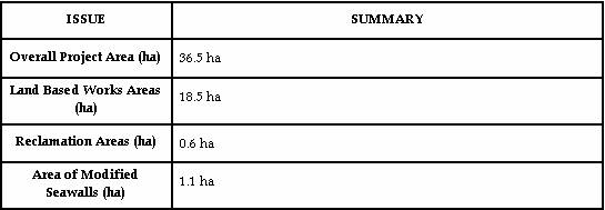
Table 3.2
presents the summary of the project details. The South Soko
Option requires 36.5 ha area, 0.6 ha is required to be reclaimed, 1.1 ha of
coastline (both artificial and natural) will be modified to enhance the
seawalls and a total dredged volume of 3.89 Mm3.
Table 3.2 Summary
of Project Description
The preliminary construction programme
is presented in Annex 3A. Site preparation works, including land
works and reclamation, are expected to take 18 months. The reclamation works is assumed as a
fast track programme in order to meet the startup schedule. Marine works, including dredging for
berth box, piling, and superstructure, are expected to be completed in about 36
months.
Following the completion of the land
works and reclamation and basic infrastructure, the formed site will be handed
over for permanent facilities construction. The
facilities portion of the work will include installation of the on-site road,
permanent drainage, tanks, equipment, piping, buildings, and the electrical
power and control systems for the process portion of the LNG terminal
facilities. The construction works
will expect to be completed in time for initial gas delivery in 2011. This gas delivery date emphasises
the project’s urgency as it would enable the timely replacement of the
depleting gas supply from the Yacheng field (off
Hainan Island - South China Sea) which is currently forecasted for the next
decade (please refer to Part 1 – Section
2).
There
may be the possibility for overlap between construction works associated with
the marine works of the proposed Emissions Control Project at the Castle Peak
Power Station ‘B’ Units. However,
cumulative impacts are not expected to occur due to the remoteness (> 4 km)
between the two project works areas.
With
the exception of the above, there are presently no committed projects that
could have the potential for cumulative impacts to occur with the construction
of the South Soko terminal. Discussions with the relevant
departments on the construction schedules of the HK-Zhuhai-Macau
Bridge, the potential Western Port Development (CT10) and the construction of
the Value Added Logistics Park (at Tai Ho)have indicated that these are
unlikely to be carried out concurrently with the construction works of the gas
pipeline. No other projects are
presently planned to be constructed in sufficient proximity to the Project to
cause cumulative effects. In light
of the above, cumulative impacts are not anticipated.