1
Terminal Design and Operating Details
This
section describes briefly the facilities at the LNG terminal.
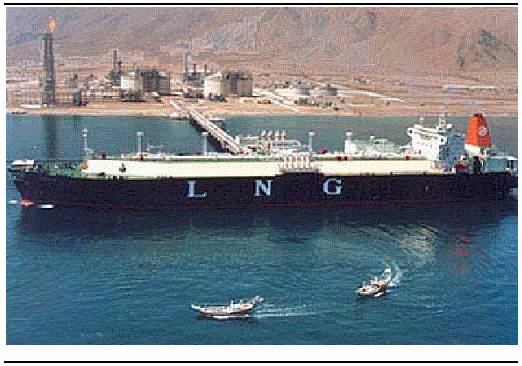
Jetty Structure
A jetty trestle structure, with a berth to
moor the carriers. The trestle will be of steel construction with a concrete
deck, abutted to a footing of rock. A typical steel trestle jetty is shown in Figure 1.1.
The pier, jetty head and ‘dolphins’ at the
berth, will have steel piles founded in the seabed approximately 50m apart. On
the jetty head, articulated piping (unloading arms) will be installed to
connect the carrier to the piping of
the onshore Terminal. The unloading arms are designed with an operating
envelope that allows for prescribed carrier movement due to environmental
factors while the arms are connected.
Figure 1.1 Typical
Steel Trestle Jetty with Berthed Vessel
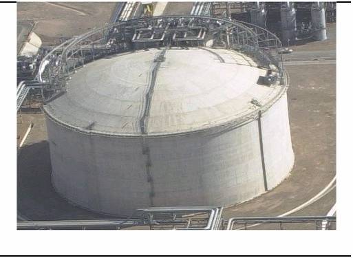
Three LNG storage tanks, each of capacity
up to 180,000 m3 will be built.
The tank design will adopt the principle
of full containment, with all tank connections made through the roof to
maximize mechanical strength and integrity. The double wall construction will
comprise an inner wall of low temperature steel and an outer wall of
pre-stressed concrete. Full containment tanks provide higher safety standards compared to
single containment tanks in view of the intrinsic robustness of the concrete
outer structure.
The inner steel container will hold the
LNG at -162°C. Cryogenic steels will be used (such as 9% Ni),
which can withstand these very low temperatures. The outer concrete wall will
include a reinforced concrete bottom slab and roof. The wall will be designed
to withstand the cryogenic temperatures involved, ie it will contain any leak
from the inner tank. Insulation materials will be applied to the space between
the steel inner container and the outer concrete tank to minimise the transfer
of heat from the environment to the bulk LNG. There will inevitably be some ‘boil-off’
of the LNG stored within the tank and this will be compressed and fed into the
send out system (see Section 1.4).
Internal tank piping will be designed to
enable bottom or top filling without the need to install any connections
through the tank wall below the liquid level. Special attention will be given
to the instrumentation on the storage tanks. Alarm and shutdown devices will be
incorporated in the design to ensure safe tank operation. These alarms and
shutdown devices will be sequenced to conform to the requirements of the
operating philosophy and the safety failure mode analysis. Tanks will also be
provided with pressure relief safety valves with a set of pressure and vacuum
breaker relief valves.
Temperature and density measuring devices along
the height of the tank will be provided as a mean to help detect stratification
(formation of layers of LNG with different densities) and avoid tank rollover.
Automatic, continuous level measurement will be provided for the storage tanks.
A typical LNG storage tank is shown in Figure 1.2.
The tank design pressure will be 290
millibars (mbar), with all tanks intended to simultaneously send out and to
receive LNG discharged by the LNG carrier. The LNG storage tanks will be fitted
with pressure-control valves (PCVs), which will prevent excess vapour from
accumulating in the tanks.
Figure 1.2 Typical
LNG Storage Tank
1.3
Boil-off Gas
(BOG) Handling System
Gas Compressors
Boil-off gases (BOGs) produced during
normal Terminal operations as a result of inevitable heat transfer from the
atmosphere to the storage tanks and piping as well as those arising from ship
unloading operations, will be sent to the BOG compressor and re-condenser for
condensing (liquefying) and re‑inclusion into the LNG bulk product stream.
Vent System
The vent system is designed for emergency
venting. The vent will not be used under normal operations.
Because of the high pressures involved,
two stages of sendout pumps are required.
First Stage LNG Sendout Pumps
Electrically driven high-capacity (first
stage) LNG sendout pumps will be installed in each LNG storage tank. These
pumps operate fully submerged in LNG and are located within pump wells,
allowing for easy pump removal, maintenance and installation. The pump wells
also serve as the discharge piping from the pumps and are connected to the
tank-top piping.
LNG from the in-tank pumps is routed
directly to the re-condenser. All boil-off vapours during normal sendout or
during carrier unloading are
routed to this drum, mixed with the LNG, and re-condensed into the bulk LNG
fluid. The re-condenser houses a packed bed of stainless‑steel pall rings (or
equivalent), which creates additional surface area for vapour-liquid contact.
Second Stage LNG
Sendout Pumps
LNG from the re-condenser on level control
is directed to the second stage sendout pumps. The second stage sendout pumps
are high‑pressure pumps, delivering LNG to the LNG Vaporisers (see Section 1.5) at a pressure of 75 to 80 bar (which could
be increased to 100 bar).
Stored LNG will need to be re-gasified in
order for it to be conveyed along the gas transportation pipework. This will be
accomplished via LNG Vaporisers, which will either utilise piped seawater (in open-rack
vaporisers) or hot combustion gases (in submerged combustion vaporisers) to
raise the temperature of the LNG to ambient temperature, thereby causing it to
re‑gasify.
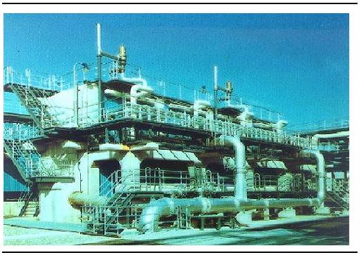
·
Open Rack Vaporisers. In open-rack vaporisers (ORVs) seawater
flows over aluminium heat exchange panels that contain tubes through which the
LNG flows. The seawater falls over the panels to a trough below and is then
discharged back to the sea. A typical vaporiser used for LNG Terminals is shown
in Figure 1.3.
·
Submerged Combined Vaporisers. Submerged Combustion Vaporisers (SCVs)
involve burning off a small amount of gas and using the heat of combustion to
maintain the temperature of a water bath. The cold LNG passes through coils
within the bath and gets vaporised.
Figure 1.3 Typical
Open Rack Vaporiser
The gas leaving the LNG Vaporiser will be
routed to the sendout gas pipework.
Fire water
A closed-loop fire water system will be
provided to protect the LNG Terminal equipment, utilities, storage and
unloading areas. The system will include main pumps and a standby mobile pump,
along with hydrants and monitors. Fire water will also be provided to protect
the berth.
Security
Security will be designed to prevent
unauthorised access and to ensure the safety and integrity of the facilities.
The site will be provided with a perimeter fence.
1.8
Utilities and
Ancillary Facilities
Nitrogen
Nitrogen in the gaseous form will be
required at the LNG Terminal for purging of equipment during maintenance as
well as during start-up. A facility for onsite nitrogen generation through PSA process or air
separation unit will be provided. Details will be finalised during detailed design.
Power
For the Black Point site, power will be
supplied from the adjoining power generation plant.
Water
Service and drinking water tanks will be
required. Maximum 80m3/hr service water will be required for startup
or shutdown operation. Seawater will be used for general washdown purposes.
Sewerage
Sewage will be treated onsite in a packaged
plant compliant with relevant local regulations.
Communications
Arrangements will be made for provision of
telephone and emergency communications.
Fuel and Materials Storage
Diesel will be stored on-site in a
permanent fuel tank. Diesel will
serve as fuel for the emergency generator. Diesel will be transported to site
by trucks.
Plant and Instrument Air
Atmospheric air will be compressed by
centrifugal compressors (each driven by electric motors) and dried for use as
both plant and instrument air.
Plant Buildings
The following permanent buildings will be
provided on site for the operational phase:
·
administration
building;
·
control
room;
·
workshop
and store room; and
·
gatehouse.
Road for Site access
will be provided.
Detailed process
flow diagram of the LNG terminal is shown in Figure 1.4, with details of the process streams indicated.
Figure 1.4 Detailed
Process Flow Diagram for
2
Operation and Maintenance of the LNG
Terminal Facilities
Upon
completion of all control systems testing, the units will be purged of oxygen
using nitrogen as the displacement gas. Various Terminal units will then be
checked for pressure leaks by pressurising and depressurising over an
approximate three-day period. The Terminal will then begin cooldown operations
using LNG. In this process, a small continuous flow of LNG will accumulate in
the tanks displacing the inert nitrogen to the atmosphere via a vent. The
cooldown will continue with LNG being introduced gradually to the piping and
other equipment.
Overview
The facilities that comprise the LNG
Terminal are described above. Operation of the Terminal facilities will
include the following significant process operations:
·
LNG
carrier approach, berthing and departure;
·
LNG
unloading from carriers at the marine facility and transfer to shore;
·
LNG
storage in onshore storage tanks;
·
Re-gasification
of the LNG to natural gas in LNG vaporisers; and
·
Final
sendout of natural gas.
2.2.2
LNG Carrier Approach
In the final segment of the approach
fairway, tugboats will assist in controlling the heading and speed of the
carrier while entering into and manoeuvring within the turning circle as well
as for the final approach towards the jetty. The tugboats will continue to
assist until the mooring operation has been completed. The number and bollard
pull of tugboats for such operations will be based on the findings of a
simulation study for the safe manoeuvring of the LNG carrier.
LNG will be pumped from the storage tanks
of the LNG carriers, through unloading arms on the jetty, to the storage tanks
onshore via insulated unloading lines.
It will take approximately 18 hrs to
unload an LNG carrier. During cargo discharge the vapour pressure in the LNGC
cargo tanks will be maintained by returning vapour from the shore. With this
balanced system, under normal circumstances, no hydrocarbons will be released
to the atmosphere from ship or shore. Unloading rates vary between 12,000 and 14,000 m3 per hour depending on the size of the carrier.
Before disconnecting the unloading arms,
remaining liquid will be drained and the arms purged with Nitrogen. The onshore liquid pipework will be left full and a minor circulation
maintained to hold the temperature at approximately -162ºC. This is required to
avoid thermal cycling of the piping.
Ballasting operations (i.e. taking on
seawater to compensate for the unloaded mass of LNG) will be concurrent with
the LNG unloading. Under normal circumstances, the LNG carrier will leave the
berth approximately 24 hours after arrival. This includes allowances for the pre-cooling operations, arrival cargo measurements,
unloading operations, cargo measurements on completion of discharge and
nitrogen displacement of unloading arms prior to disconnection.
To minimise the potential for LNG
spillage, the carrier and shore Emergency Shut Down (ESD) systems will be
interlinked such that an unusual event on either will automatically activate a
transfer system shutdown (ESD I) and in a severe case will also disconnect the
unloading arms (ESD II). An ESD I test will be completed before the start of
unloading operations. In the event of an ESD II unloading arm disconnection,
LNG spillage would be very small due to the activation of isolation valves on
either side of the Emergency Release coupler.
Before and during LNG transfer operations,
a safety zone of approximately 250m around the LNG carrier will be maintained.
2.2.4
Onshore Modes of Operation
The LNG Terminal will operate in two main
modes of operation:
·
Unloading Mode – The unloading
mode is the period when an LNG carrier is moored to the jetty and is connected via the unloading
arms and the jetty piping to the onshore storage tank. The pumps on the LNG
carrier will transfer the LNG in both the unloading and the re-circulation
lines to the onshore storage tanks. At the end of unloading, pressurised
nitrogen gas will be used to purge the arms of LNG before disconnecting.
·
Holding Mode – The holding mode
is the period when no unloading takes place. During the holding mode, cryogenic
conditions will be maintained in the unloading line by circulating LNG to the
jetty head and back to the onshore storage tanks or the sendout system via a dedicated re-circulation line.
During both of these modes of operation,
sendout of LNG to BBPS will continue.
Utilities required during the operation of
the Terminal facilities are summarised in Table
2.1.
Table 2.1 Utilities
|
Material |
Use |
Handling and Transport |
Storage quantity |
|
Diesel |
Operation (for emergency generator) |
Truck |
20 m3
|
|
Liquified
nitrogen |
Maintenance (purging) |
Drum to be
filled via truck (or ro-ro ferry) every 2 weeks |
25 m3 |
|
Hydrochloric
acid 30% HCl |
Maintenance; neutralise using caustic and flush
to ocean |
Aboveground
storage on a skid |
200 L |
|
Caustic
soda 10% NaOH |
To neutralize the acid from maintenance of the
electro-chlorination units |
Drum |
2 m3 |
|
Raw
water |
Fire fighting and for service |
Pump |
1,500 m3 |
|
Seawater
|
Vaporisers |
Pump |
|
|
Electricity
|
|
132 kV
or 111 kV |
|