Contents: Water Quality Impact Assessment
4.1 Introduction
4.2 Objectives
4.3 Legislation,
Standards and Guidelines
4.4 Assessment
Approach
4.5 Baseline
Conditions
4.6 Evaluation
Criteria
4.7 Construction
Phase Impact Assessment
4.8 Operational
Phase Impact Assessment
4.9 Impact
Mitigation
4.10 Residual
Impact Assessment
4.11 Environmental
Monitoring & Audit Requirements
4.12 Conclusions & Recommendations
4.13 References
4
Water Quality Impact Assessment
4.1
Introduction
4.1.1.1
This section presents the Water Quality Impact
Assessment (WQIA) for the construction and operational phases of the Project.
4.1.1.2
The aim of the WQIA is to assess and evaluate
impacts of the proposed Project upon water sensitive receivers within the Study
Area and to identify measures to avoid or otherwise reduce predicted impacts to
within acceptable levels.
4.2
Objectives
4.2.1.1
This section has been compiled in accordance
with the evaluation criteria and assessment guidelines as presented in Annexes
6 and 14 respectively of the EIA-TM, and with reference to the requirements of
Clause 3.4.1 of the EIA Study Brief.
4.2.1.2
Key objectives of the water quality impact
assessment include the following:
· To collect
and review background information on the existing and planned water system(s)
and their respective sensitive receivers;
· To characterise water and sediment quality and water sensitive receivers
based on existing information or appropriate site survey and tests;
· To identify and analyse physical, chemical and biological disruptions of
marine water system(s) arising from the project construction and operation;
· To predict, quantify and assess any water quality impacts arising from
the Project on the water system(s) and the sensitive receivers by appropriate
mathematical modelling techniques;
· To identify and evaluate the best practicable dredging methods to
minimize dredging and dumping requirements;
· To evaluate the potential of and associated water quality impacts
arising from accidental vessel collisions within the Project area during
construction and maintenance of the wind farm;
· To identify and quantify all dredging, fill extraction, filling,
mud/sediment transportation and disposal activities and requirements; and
· To devise
mitigation measures to avoid or minimize potential impacts, in particular
suitable dredging and disposal methods to mitigate any adverse impacts.
4.3
Legislation, Standards and
Guidelines
4.3.1.1
Reference
has been made to the following local legislation governing water quality:
4.3.2
Water Pollution Control Ordinance (WPCO) (Cap. 358)
4.3.2.1
Defines the boundaries of the ten local Water
Control Zones (WCZs) and specifies the requirements Water Quality Objectives
(WQOs). The WQOs set limits for
different parameters to be achieved for maintaining the water quality within the
WCZs. In accordance with the Study
Brief, the Study Area of the project should cover the Mirs Bay,
Port Shelter, Eastern Buffer and Junk Bay WCZs. Table 4.1
summarises the WQOs for these WCZs.
Table 4.1 Summary
of WQOs for Mirs Bay,
Junk Bay, Eastern Buffer and Port Shelter
Water Control Zones
|
Parameter
|
WQOs
|
WCZ / Part (s) of zone /Subzone to which
the WQO applies
|
|
Dissolved Oxygen (DO)
(bottom)
|
Not less than 2 mg/L for 90% samples;
|
Marine waters of Mirs Bay, Junk Bay,
Eastern Buffer and Port Shelter WCZs, and Fish Culture
Subzones
|
|
DO
(Depth-averaged)
|
Not less than 4 mg/L for 90% samples
|
Marine waters of Mirs Bay, Junk Bay,
Eastern Buffer and Port Shelter WCZs
|
|
|
Not less than 5 mg/L
|
Fish Culture Subzones
|
|
Nutrients
|
Annual mean depth-aver aged inorganic
nitrogen not to exceed 0.1 mg/L
|
Port Shelter WCZ
|
|
Annual mean depth-aver aged inorganic
nitrogen not to exceed 0.3 mg/L
|
Marine waters of Mirs Bay
and Junk Bay WCZs
|
|
Annual mean depth-aver aged inorganic
nitrogen not to exceed 0.4 mg/L
|
Marine waters of Eastern Buffer WCZ
|
|
Unionised ammonia
|
Annual mean not to exceed 0.021 mg/L
|
Marine waters (all zones) of Mirs Bay, Junk Bay,
Eastern Buffer and Port Shelter WCZs
|
|
E. coli
|
Annual geometric mean not to exceed
610cfu/100mL
|
Secondary contact recreation subzones
Port Shelter and Mirs Bay WCZs
|
|
Annual geometric mean not to exceed
610cfu/100mL
|
Fish culture subzones in Port Shelter,
Junk Bay,
Mirs Bay and Eastern Buffer WCZs
|
|
pH
|
To be in the range 6.5 - 8.5, change
due to waste discharge not to exceed 0.2
|
Marine waters of Mirs Bay, Junk Bay,
Eastern Buffer and Port Shelter WCZs
|
|
Change due to waste discharge not to exceed
10% of natural ambient level
|
Whole Zone of Mirs
Bay, Junk Bay,
Eastern Buffer and Port Shelter WCZs
|
|
Temperature
|
Change due to waste discharge not to
exceed 2°C
|
Whole Zone of Mirs
Bay, Junk Bay,
Eastern Buffer and Port Shelter WCZs
|
|
Suspended Solids (SS)
|
Waste discharge not to raise the
natural ambient level by 30% nor cause the accumulation of SS which may
adversely affect aquatic communities
|
Marine waters of Mirs Bay, Junk Bay,
Eastern Buffer and Port Shelter WCZs
|
|
Toxicants
|
Not to be present at levels producing
significant toxic effect
|
Whole Zone of Mirs
Bay, Junk Bay,
Eastern Buffer and Port Shelter WCZs
|
4.3.3
Environmental Impact Assessment Ordinance (Cap. 499. S.16)
4.3.3.1
Technical Memorandum on Environmental Impact
Assessment Process (EIAO-TM), Annexes 6 and 14 specifies
the assessment method and criteria for water quality impact assessment. This section follows the details of the
assessment criteria and guidelines for evaluating water pollution.
4.3.4
Water Supplies Department Water Quality Objectives
4.3.4.1
Stipulate a set of water quality objectives for
water quality at seawater intakes. Table 4.2 presents the relevant criteria. The suspended solids and dissolved
oxygen requirements are most relevant to this EIA study.
Table 4.2 Water
Supplies Department standards at Seawater Intakes
|
Parameter
|
WSD Target Limit
|
|
Colour
|
<
20 HU
|
|
Turbidity
|
<
10 NTU
|
|
Threshold
Odour Number
|
<
100 Odour Unit
|
|
Ammoniacal
Nitrogen
|
<
1 mg/L
|
|
Suspended
Solids
|
<
10 mg/L
|
|
Dissolved
Oxygen
|
>
2 mg/L
|
|
Biochemical
Oxygen Demand
|
<
10 mg/L
|
|
Synthetic
Detergents
|
<
5 mg/L
|
|
E. coli
|
<
20,000 no./100mL
|
4.3.5
Technical Memorandum on Standards
for Effluents Discharged into Drainage and Sewerage Systems Inland and Coastal
Water
4.3.5.1
Provides guidance on the permissible effluent discharges
for foul sewers, storm water drains, inland and coastal waters. Should any effluent be generated from
this Project, the effluent quality should comply with the standards for
effluents discharged into the inshore waters or marine waters of Junk Bay WCZ,
Eastern Buffer WCZ and Mirs Bay WCZ.
4.3.6
Environment, Transport and Works
Bureau Technical Circular (Works) no. 34/2002 Management of Dredged/Excavated
Sediment
4.3.6.1
Sets
out the procedure for seeking approval to dredge/ excavate sediment and the
management framework for marine disposal of dredged/ excavated sediment. The
Technical Circular also specifies the requirements for determination of
sediment quality, classification of sediment and disposal arrangement for the
sediment.
4.4
Assessment Approach
4.4.1
Marine Activities
4.4.1.1
Various
foundation options and construction methods have been evaluated in order to
minimize the potential environmental impacts of the proposed Project. Details of alternative site and
construction options are presented in Section 2 of this EIA Report. Table 4.3
summarizes the preferred foundation and substructure options for Project
development.
Table 4.3 Summary
of Preferred Foundation and Substructure Options
|
Item
|
Preferred Type
|
|
Foundation
|
Suction Caisson Foundations
|
|
Substructure
|
3 or 4 legged jacket substructure
|
4.4.1.2
Foundation
installation requires the removal of water from inside of the suction caissons
to the ambient water through pumping.
The pumped out water may contain a certain amount of sediment. Transmission power cables and collection
power cables will be installed by jetting, with the exception of the section
located within Junk
Bay. This section, approximately 3-km long,
requires anchor protection which will require the deployment of a dredger. Both jetting and dredging would cause
release of sediment into the water body.
4.4.2
Modelling Tool
4.4.2.1
A fine grid model has been developed using the
Delft3D suite of models for prediction of the impacts due to sediment
dispersion in the construction phase and the changes in hydrodynamic regime
within the Study Area after the completion the Project. Details of the model setup and
calibration are presented in the Report
on Wind Farm Model Calibration (Appendix 4A
refers).
4.4.2.2
The Delft3D-PART module using a particle
tracking method has also been used to simulate the concentration distribution
of suspended solids (SS). Depletion
of dissolved oxygen (DO) is calculated based on the modelled SS concentrations
at WSRs. The concentrations of the other pollutants at the WSRs are estimated
based on the results predicted by the model.
4.4.3
Pollution Loads
4.4.3.1
The proposed works will lead to the release of
sediment and contaminants into the ambient water, resulting in potential water
quality impacts. Tidal currents are
the controlling factor for the dispersion of sediment disturbed by foundation
installation and cabling works.
Sediment release rates for different activities are estimated below
based on the characteristics of the preferred construction methods and
equipment:
Dredging
4.4.3.2
Rock amour protection involving the dredging of
a trapezoidal trench is proposed for the cable in Junk Bay. The approximate volume of dredged
sediment is 135,000m3, based on an approximately 3km long trapezoidal trench of nominal 3m depth (shown in Figure 3.2). The sediment
would be extracted by closed-grab dredging followed by backfilling with
rock. The maximum dredging
rate for the grab dredger is not expected to exceed 6,300m3 per day.
Sediment loss rates depend on the
size of the grab dredger, small dredgers generally have higher sediment loss
rates. The approximate range of the
sediment loss rates for large and small dredgers is between 12 kg/m3
and 25 kg/m3 (John et al.,
2000). In this study, a
conservative value of the sediment loss rate for the grab dredger of 25 kg/m3
is assumed.
4.4.3.3
A portion of dredging work in Junk Bay
is carried out near to the shore and may not be allowed between 19:00 and 07:00
hours on normal weekdays. It is assumed
that the work would be carried out over 12 hours per day with 6 working days
per week for the transmission cable section in Junk Bay. The worst-case scenario for dredging
includes two grab dredgers operating at the same time with a minimum separation
of 100 m. Estimation of the
sediment release rate for grab dredging is given below:
Grab size = 11 m3
Working hours = 12 hr/day
No. of dredgers = 2 dredgers
Daily dredging rate by two dredgers = 6,300m3
Sediment loss rate (S-factor) = 25 kg/m3
Sediment release rate =  =
= 
4.4.3.4
The sediment release due to grab dredging is
assumed to be continuous and the sediment load is allocated in the whole water
column to represent the sediment loss during the lift motion of the grab.
Jetting
4.4.3.5
The maximum depth of cable embedment by the
jetting machine is 5 m and the width of the trench is approximately 0.4 m. The maximum jetting speed of the jetting
machine is 150 m/hour or 0.0417 m/s.
Therefore, the jetting rate (rate of disturbance) is 0.0417 m/s ´ 0.4
m wide ´ 5 m deep trench = 0.0834 m3/s.
4.4.3.6
The calculation of sediment release rate for
jetting is based on the following relationship:
Sediment
release rate (kg/s) = jetting rate (m3/s) ´ dry density of the sediment (kg/m3) ´ percentage of loss rate (%)
4.4.3.7
It is assumed that the percentage of loss rate
(% of the disturbed sediment becomes suspension) is 20%. Based on the sediment analysis for this
Project, the dry density of the sediment is about 1,105 kg/m3. The sediment release rate for jetting is
therefore:
Sediment release rate (kg/s) =  =
= 
4.4.3.8
Release of sediment is concentrated at the
bottom layer of the water column for jetting and is assumed as a continuous
moving source at a speed of 150 m/hr along the offshore transmission power
cable sections and at the foundation site.
A 16 working hours per day with 6 working days per week is assumed for
the jetting operation in this area.
Water Pumping Out from
Suction Caissons
4.4.3.9
During the suction caisson installation, water
inside the suction caisson would be pumped out and discharged into the
surrounding water. The total amount
of water to be pumped out of each foundation is not expected to exceed 8,500 m3. The pumping rate would not exceed 300 m3
/ hour per pump, or 1,200 m3 / hour per foundation.
4.4.3.10
It is assumed that at the beginning of the
operation the water pumped from the suction caissons would be free of suspended
solids as the upper water layer within the foundation would be extracted. As the pumping progresses it may be
expected that the lowest water layer within the foundation would contain a
certain amount of suspended solids from the seawater / sediment interface.
4.4.3.11
To
verify these assumptions a field trial was conducted in May 2008 to measure
turbidity and / or SS concentrations at the discharge location and a various
points downstream from the discharge location. Field measurements revealed that
the increase in SS above ambient levels was negligible throughout the trial
installation, with no sediment plume was observed using underwater video or
visible at the water surface.
4.4.3.12
To take
a conservative approach for estimating the sediment release rate used in this water quality impact assessment, it is assumed that
the water pumped out from the suction caissons contains an average of 15%
sediment, which has been verified to
be much higher than the result of the field water quality monitoring of a field
trial presented in Section 4.7.2. The dry density of the sediment, as
determined through fieldwork, is 1,105 kg/m3. The sediment concentration in the
water pumped out from the suction caissons is thus 165.8 kg/m3.
4.4.3.13
With reference to the Liquefied Natural Gas
Receiving Terminal and Associated Facilities EIA, 80% of the sediment would
fall from the water column to the seabed within a 70 m radius. The percentage of the disturbed sediment
in suspension is assumed to be 20%.
The sediment release rate for each foundation site has therefore been
calculated as:
 =
= 
4.4.3.14
The suction pumps are installed at the top of
the suction caissons. Discharge of
the water would be conservatively assumed to be highest at 10 m above the seabed
as the whole suction caisson will penetrate into the seabed in time. It is also conservatively assumed that
the duration of the discharge is 8 hours for each foundation.
Modelling Scenarios
4.4.3.15
As shown in Figure 4.1, the proposed
cable route has been divided into three sections in order to derive the
worst-case scenarios. Section 1
represents the transmission cable section in Junk Bay
that requires anchor protection to be put in place within a dredged
trench. Two sediment release points
(P1 and P2) have been nominated within this section for different scenarios.
4.4.3.16
No more than two grab dredgers would be deployed
and operate at the same time with a minimum separation of 100 m at each
proposed sediment release point.
Sediment release point P1 is located near the Seawater Intakes for WSD
Pumping Station at Tseung Kwan O and the coral communities at Chiu Keng
Wan. Sediment release point P2 is
selected, so that it is located near the Coral Communities at Fat Tong Chau
West.
4.4.3.17
Sections 2 and 3 represent the remaining
offshore transmission power cable sections. Installation of the cables will be by
jetting only. Sediment
release points P3 and P4 are the sources representing the movement of the
jetting machine within Section 2 and Section 3 respectively. Only one jetting machine would be
deployed for cable laying.
Therefore, jetting can only take place at one location in the entire
Project area at any one time. The
jetting operation for this Project takes only one pass per cable installation
to fluidize the sediment and lay the cable.
4.4.3.18
The distance of each of the two sections is
approximately 11 km. Considering
the maximum jetting speed of the jetting machine of 150 m/hr, the jetting
operation can be expected to take 6 - 9 days depending on the actual length of
the working day. As the period
required to complete a single pass is less than the model simulation period of
15 days, it is conservatively assumed that the jetting machine continuously
moves along the section throughout the entire simulation period. This conservative approach covers
different tidal stages during the release of sediment from the jetting machine.
4.4.3.19
At the wind farm foundation site, there would be
a maximum of three foundations installed concurrently. Three sediment release points (P5, P6
and P7) which are the closest to the dredging site in Junk Bay and jetting
operation of the transmission power cable sections are allocated on the south-eastern
boundary of the foundation site to take into account the worst situation of
cumulative impact from the construction activities of the Project at the
western side of the Study Area.
These sediment release point locations are also near the coral communities
at Tuen Chau Tsai East and at One Foot Rock to represent the worst situation.
4.4.3.20
In the case where foundation installations are
carried out near the Victor Rock, which is one of the identified WSRs, three
sediment release points (P8, P9 and P10) allocated at the north-eastern
boundary of the foundation site in the closest proximity to this WSR are
selected. Jetting for the array
cable laying is also considered to be conducted adjacent to these points to
represent the worst situation that may adversely affect the coral communities
at Victor Rock. A moving source at
sediment release point (P11) is used to represent the operation of the jetting
machine.
4.4.3.21
There are in total five worst-case scenarios for
water quality impact assessment developed from a combination of different
sediment release points that represent different construction activities for
the entire project area. Table 4.4 presents all the worst-case scenarios.
Table 4.4 Worst-case
Scenarios
|
Scenario
|
Sediment Release Activities from the
Wind Farm Project
|
Concurrent Project
|
|
Scenario
1
|
Section 1 - Dredging in Junk Bay
at P1
Section 2 - Jetting at P3
Foundation Site - Water pumping at P5-P7
|
§
East Tung Lung Chau mud disposal area
§
Tseung Kwan O Development
|
|
Scenario
2
|
Section 1 - Dredging in Junk Bay
at P1
Section 3 - Jetting at P4
Foundation Site - Water pumping at P5-P7
|
§
East Ninepins mud disposal area
§
Tseung Kwan O Development
|
|
Scenario
3
|
Section 1 - Dredging in Junk Bay
at P2
Section 2 - Jetting at P3
Foundation Site - Water pumping at P5-P7
|
§
East Tung Lung Chau mud disposal area
§
Tseung Kwan O Development
|
|
Scenario
4
|
Section 1 - Dredging in Junk Bay
at P2
Section 3 - Jetting at P4
Foundation Site - Water pumping at P5-P7
|
§
East Ninepins mud disposal area
§
Tseung Kwan O Development
|
|
Scenario
5
|
Section 1 - Dredging in Junk Bay
at P2
Foundation Site - Water pumping at P8-P10
& Jetting at P11
|
§
East Ninepins mud disposal area
§
Tseung Kwan O Development
|
Scenario 1
4.4.3.22
Scenario 1 is to simulate the impacts due to dredging
at the nearest point to the seawater intakes for the WSD pumping station at
Tseung Kwan O and coral communities at Chiu Keng Wan in Junk Bay. Dredging takes place at sediment release
point P1 in Section 1. In order to
take into account the potential impacts from the other activities of the same
Project, jetting in Section 2 at source P3 and installation of three
foundations at the foundation site (as represented by sediment release points
P5 to P7) are also included to form this worst-case scenario.
Scenario 2
4.4.3.23
Scenario 2 is similar to Scenario 1 but jetting
takes place in Section 3 of the transmission power cable section as represented
by a moving source P4 for. Dredging
also occurs at P1 in Section 1 of the transmission power cable section and water
pumping operation takes place at P5 to P7 at the foundation site.
Scenario 3
4.4.3.24
Scenario 3 is to simulate the situation where
dredging takes place nearest to the coral communities at Fat Tong Chau West in Junk Bay. Release of sediment due to dredging
operation is at P2 in Section 1 and concurrent Jetting is assumed in Section 2
at the moving source P3. Three
sediment release points (P5, P6 and P7) representing the water pumping
operation are located at the foundation site.
Scenario 4
4.4.3.25
Scenario 4 is similar to Scenario 3 but jetting
takes place in Section 3 of the transmission power cable section as represented
by a moving source P4. Dredging is
also assumed to carry out at P2 in Section 1, which is located nearest to the
coral communities at Fat Tong Chau West.
Water pumping operation takes place at P5 to P7 within the foundation
site.
Scenario 5
4.4.3.26
Scenario 5 is to simulate the situation where
jetting and water pumping operation for installation of three foundations are
located nearest to Victor Rock. The
jetting operation is represented by a moving source P11 for release of sediment
and water pumping operation is represented by sediment release points P8, P9
and P10 at the north-eastern boundary of the foundation site. Dredging is assumed to carry out at
sediment release point P2 in section 1 of the transmission power cable section.
4.4.3.27
The projects or activities that would be carried
out concurrently with this Project and are located near the Works include
Tseung Kwan O Development and East Tung Lung Chau and East Ninepins mud
disposal area. The assessment of
cumulative impacts takes into account the sediment release from these projects
in the five worst-case scenarios. EIA’s for the Cruise Terminal at Kai Tak
project and the Wan Chai Development Phase II project have suggested that coral
colonies be translocated from their current locations to small sites in Junk Bay.
Figure 4.2 shows that these
potential coral translocation sites are approximately 1.6 kilometers away from
the cable corridor. As a result, no adverse impacts are anticipated at the
potential coral translocation sites..
4.4.3.28
The reclamation activity of Tsueng Kwan O
Development together with the dredging operation of this Project may further increase
the SS elevation in Junk
Bay, and is included in
all the worst-case scenarios for cumulative impact assessment. The operation of the East Tung Lung Chau
mud disposal area would not overlap with the disposal activity at East Ninepins
mud disposal area. Sediment release
from the disposal activity at East Tung Lung Chau mud disposal area is only
included in Scenarios S1 and S3 where jetting operation takes place near this
disposal area. Jetting operation as
considered in Scenarios 2 and 4 would be carried out near the East Ninepins mud
disposal area. Therefore, sediment
release from the disposal activity at East Ninepins mud disposal area is
included in Scenarios 2 and 4 for cumulative impact assessment. The disposal activity at East Ninepins,
which is also located near the dredging operation in Junk Bay,
is included in Scenario 5 together with the jetting operation at the foundation
site to form the worst-case scenario for cumulative impact assessment.
4.4.3.29
The approach of this study is to first examine
the worst-case scenarios without any mitigation measures for reducing sediment
release from jetting, dredging and water pumping operations. Mitigated scenarios are, however, also
included in the assessment to achieve compliance with the WQOs. Therefore, the water quality impacts during the construction stage
of the Project examine both the unmitigated and mitigated scenarios.
4.4.3.30
During
the operational stage, the model
runs also include drogue
tracking for oil spill to assess the areas that are potentially affected by any potential oil spill events.
4.4.4
Frictional Effects due to Wind Turbine Sub-structures
4.4.4.1
The sub-structures of the wind turbines that are
submerged in the sea cause friction on tidal flow. The following method is used to account
for the hydrodynamic impact due to the submerged sub-structures.
4.4.4.2
As the hydrodynamic model grid size is larger
than the wind turbine (~30m diameter[2]),
it is not practicable to correspondingly refine the model grid size as the
computational time would be significantly increased. The frictional effects due to submerged
bridge piers or vertical structures were modelled and assessed in other EIA
studies[3]. A similar approach is therefore adopted
in this study to model and assess frictional effects caused by the
sub-structures of the wind turbines.
With this approach, additional quadratic friction terms are added to the
momentum equations to represent the frictional effects of wind turbine columns
on the hydrodynamics. The
mathematical expressions for calculating the loss coefficients for accounting
the frictional effects are given as follows:
 (4-1)
(4-1)
Where,
 is the density of
water;
is the density of
water;
 ,
,  and
and  are sizes of the grid
cell in x, y and z directions;
are sizes of the grid
cell in x, y and z directions;
 is the velocity,
  is the magnitude
of the velocity, U and V are velocity components in x and y directions;
is the magnitude
of the velocity, U and V are velocity components in x and y directions;
 and
and  are the loss coefficients
in x and y directions; and
are the loss coefficients
in x and y directions; and
Fx and Fy are drag
forces induced by the sub-structure of the wind turbine in a grid cell, which
are calculated as:
 (4-2)
(4-2)
Where,
n is the number of the turbine columns in the
grid cell
 is the drag
coefficient;
is the drag
coefficient;
D is the diameter of the turbine column;
 is the effective
approach velocity;
is the effective
approach velocity;
 is the magnitude
of the effective velocity,
is the magnitude
of the effective velocity,  and
and  are the effective
velocity components in x and y directions;
are the effective
velocity components in x and y directions;
 is the total
cross-section area;
is the total
cross-section area;
 is the effective
cross-section area which is the difference between the total cross-section area
and the area blocked by the turbine columns;
and
is the effective
cross-section area which is the difference between the total cross-section area
and the area blocked by the turbine columns;
and
 is the ratio of
the total cross-section area to the effective cross-section area.
is the ratio of
the total cross-section area to the effective cross-section area.
Combining Equations (4-1) and
(4-2), the loss coefficient used in the hydrodynamic model is expressed as:
 (4-3)
(4-3)
4.4.4.3
It is conservatively assumed that the diameter
of the sub-structure is the same as that of the base footprint width of the
foundation, i.e. 30 m. The
estimated loss coefficient for the sub-structure in the wind farm location is
about 0.2.
4.5
Baseline Conditions
4.5.1
Description of the Environment
4.5.1.1
To assess the existing water quality conditions
in the study area covering the Mirs
Bay, Port Shelter,
Eastern Buffer and Junk Bay WCZs, the most recently published monitoring data
collected at the EPD marine water monitoring stations near the proposed wind
farm and transmission power cable route have been reviewed. The data can be used to represent the
baseline water quality conditions at representative water sensitive
receivers.
4.5.1.2
The selected EPD marine water monitoring
stations include MM8, MM9 and MM14 in the Mirs Bay WCZ;
PM1, PM4, PM6, PM7, PM8, PM9 and PM11 in the Port Shelter WCZ; EM1, EM2 and EM3 in the Eastern Buffer WCZ; and JM3 and JM4 in the Junk Bay WCZ. A summary of EPD monitoring data
collected in between 2002 and 2006 is presented in Table
4.5 to Table 4.8.
Table 4.5 Summary Statistics of Marine Water Quality in Junk Bay WCZ
between 2002 and 2006
|
Parameter
|
EPD Monitoring Station
|
|
|
JM3
|
JM4
|
|
Temperature (ºC)
|
|
23.3
|
23.1
|
|
(15.9 - 29)
|
(15.8 - 28.7)
|
|
Salinity (ppt)
|
|
32.5
|
32.7
|
|
(20.9 - 34.9)
|
(22.2 - 35)
|
|
Dissolved Oxygen (mg/L)
|
|
6.2
|
6.1
|
|
(3.2 - 9.8)
|
(3.2 - 9.9)
|
|
Bottom
|
6.2
|
6.1
|
|
(3.2 - 9.8)
|
(3.2 - 9.9)
|
|
Dissolved Oxygen (DO) (%
saturation)
|
|
87.0
|
85.9
|
|
(45 - 145)
|
(46 - 146)
|
|
Bottom
|
87.0
|
85.9
|
|
(45 - 145)
|
(46 - 146)
|
|
pH value
|
|
8.1
|
8.1
|
|
(7.7 - 8.7)
|
(7.7 - 8.6)
|
|
Secchi Disc Depth (m)
|
|
2.5
|
2.5
|
|
(1 - 4.1)
|
(0.5 - 4.5)
|
|
Turbidity (NTU)
|
|
9.1
|
9.8
|
|
(1.7 - 17.9)
|
(2.6 - 37.4)
|
|
Suspended Solids (SS) (mg/L)
|
|
3.3
|
4.9
|
|
(0.6 - 10)
|
(0.5 - 110)
|
|
5-day Biochemical Oxygen Demand
(BOD5) (mg/L)
|
|
0.9
|
0.8
|
|
(0.2 - 5.9)
|
(0.1 - 5.8)
|
|
Ammonia Nitrogen (NH3-N) (mg/l)
|
|
0.1
|
0.1
|
|
(0.007 - 0.25)
|
(0.009 - 0.24)
|
|
Unionised Ammonia (mg/L)
|
|
<0.1
|
<0.1
|
|
(0 - 0.014)
|
(0 - 0.022)
|
|
Nitrite Nitrogen (mg/L)
|
|
<0.1
|
<0.1
|
|
(0.002 - 0.1)
|
(0.002 - 0.1)
|
|
Nitrate Nitrogen (mg/L)
|
|
0.1
|
0.1
|
|
(0.003 - 0.38)
|
(0.008 - 0.36)
|
|
Total Inorganic Nitrogen (TIN)
(mg/L)
|
|
0.2
|
0.1
|
|
(0.02 - 0.59)
|
(0.03 - 0.63)
|
|
Total
Kjeldahl Nitrogen (mg/L)
|
|
0.2
|
0.2
|
|
(0.05 - 0.49)
|
(0.05 - 0.46)
|
|
Total Nitrogen (mg/L)
|
|
0.3
|
0.3
|
|
(0.1 - 0.81)
|
(0.08 - 0.8)
|
|
Orthophosphate Phosphorus (mg/L)
|
|
<0.1
|
<0.1
|
|
(0.002 - 0.038)
|
(0.002 - 0.054)
|
|
Total Phosphorus (mg/L)
|
|
<0.1
|
<0.1
|
|
(0.02 - 0.07)
|
(0.02 - 0.07)
|
|
Silica
(as SiO2) (mg/L)
|
|
0.6
|
0.6
|
|
(0.08 - 1.9)
|
(0.05 - 2)
|
|
Chlorophyll-a
|
|
3.4
|
2.8
|
|
(μg/L)
|
(0.4 - 30)
|
(0.4 - 33)
|
|
E. coli
|
|
277.2
|
225.8
|
|
(count/100 mL)
|
(1 - 7300)
|
(1 - 3400)
|
|
Faecal
|
|
511.5
|
541.4
|
|
Coliforms
|
(2 - 11000)
|
(2 - 8400)
|
|
(count/100 mL)
|
|
|
Table 4.6 Summary Statistics of Marine Water Quality in Mirs Bay WCZ between 2002 and 2006
|
Parameter
|
EPD Monitoring Station
|
|
MM8
|
MM13
|
MM14
|
|
Temperature (ºC)
|
|
22.9
|
23.1
|
22.9
|
|
(15.4
- 29.7)
|
(15.1
- 30.1)
|
(15
- 29.8)
|
|
Salinity (ppt)
|
|
33.1
|
33.2
|
33.2
|
|
(21.2
- 35.1)
|
(22.1
- 35.2)
|
(23.1
- 35.2)
|
|
Dissolved Oxygen
(mg/L)
|
|
6.5
|
6.6
|
6.6
|
|
(2.5
- 9.2)
|
(2.4
- 9.9)
|
(2.8
- 9.1)
|
|
Bottom
|
6.5
|
6.6
|
6.6
|
|
(2.5
- 9.2)
|
(2.4
- 9.9)
|
(2.8
- 9.1)
|
|
Dissolved Oxygen (DO)
(% saturation)
|
|
91.5
|
92.7
|
92.4
|
|
(35
- 134)
|
(34
- 149)
|
(40
- 134)
|
|
Bottom
|
91.4
|
92.7
|
92.5
|
|
(35
- 134)
|
(34
- 149)
|
(40
- 134)
|
|
pH value
|
|
8.2
|
8.2
|
8.2
|
|
(7.9
- 8.7)
|
(7.9
- 8.6)
|
(7.8
- 8.7)
|
|
Secchi Disc Depth (m)
|
|
3.8
|
4.6
|
4.1
|
|
(1
- 10)
|
(1.3
- 13)
|
(1.5
- 10)
|
|
Turbidity (NTU)
|
|
10.9
|
12.2
|
9.7
|
|
(0.8
- 98.7)
|
(0.7
- 149.6)
|
(0.9
- 23.3)
|
|
Suspended Solids (SS)
(mg/L)
|
|
4.2
|
5.6
|
4.0
|
|
(0.5
- 26)
|
(0.5
- 210)
|
(0.5
- 24)
|
|
5-day Biochemical
Oxygen Demand (BOD5) (mg/L)
|
|
0.6
|
0.5
|
0.6
|
|
(0.1
- 3.2)
|
(0.1
- 3.5)
|
(0.1
- 3.6)
|
|
Ammonia Nitrogen
(NH3-N) (mg/l)
|
|
<0.1
|
<0.1
|
<0.1
|
|
(0.005
- 0.067)
|
(0.005
- 0.051)
|
(0.005
- 0.06)
|
|
Unionised Ammonia
(mg/L)
|
|
<0.1
|
<0.1
|
<0.1
|
|
(0
- 0.006)
|
(0
- 0.005)
|
(0
- 0.006)
|
|
Nitrite Nitrogen
(mg/L)
|
|
<0.1
|
<0.1
|
<0.1
|
|
(0.002
- 0.053)
|
(0.002
- 0.045)
|
(0.002
- 0.045)
|
|
Nitrate Nitrogen
(mg/L)
|
|
<0.1
|
<0.1
|
<0.1
|
|
(0.002
- 0.35)
|
(0.002
- 0.57)
|
(0.002
- 0.25)
|
|
Total Inorganic Nitrogen
(TIN) (mg/L)
|
|
<0.1
|
<0.1
|
<0.1
|
|
(0.01
- 0.4)
|
(0.01
- 0.62)
|
(0.01
- 0.29)
|
|
Total Kjeldahl Nitrogen (mg/L)
|
|
<0.1
|
<0.1
|
<0.1
|
|
(0.05
- 0.26)
|
(0.05
- 0.38)
|
(0.05
- 0.28)
|
|
Total Nitrogen (mg/L)
|
|
0.2
|
0.1
|
0.1
|
|
(0.05
- 0.63)
|
(0.05
- 0.8)
|
(0.05
- 0.48)
|
|
Orthophosphate
Phosphorus (mg/L)
|
|
<0.1
|
<0.1
|
<0.1
|
|
(0.002
- 0.019)
|
(0.002
- 0.018)
|
(0.003
- 0.019)
|
|
Total Phosphorus
(mg/L)
|
|
<0.1
|
<0.1
|
<0.1
|
|
(0.02
- 0.24)
|
(0.02
- 0.13)
|
(0.02
- 0.04)
|
|
Silica (as SiO2) (mg/L)
|
|
0.5
|
0.5
|
0.5
|
|
(0.06
- 1.5)
|
(0.06
- 3.2)
|
(0.06
- 1.7)
|
|
Chlorophyll-a
|
|
2.0
|
1.8
|
1.8
|
|
(μg/L)
|
(0.3
- 19)
|
(0.4
- 20)
|
(0.2
- 19)
|
|
E. coli
|
|
5
|
2
|
3
|
|
(count/100 mL)
|
(1
- 25)
|
(1
- 4)
|
(1
- 13)
|
|
Faecal
|
|
2
|
2
|
2
|
|
Coliforms
|
(1 - 8)
|
(1 - 6)
|
(1 - 9)
|
|
(count/100 mL)
|
|
|
|
Notes:
1. Date
presented are depth-averaged, expect as specified.
2. Data
presented are arithmetic means of the depth-averaged results except for E. coli
and faecal coliforms, which are annual geometric means.
3. Data
in brackets indicate the ranges.
Table 4.8 Summary Statistics of Marine Water Quality in Eastern Buffer WCZ between 2002 and
2006
|
Parameter
|
EPD Monitoring Station
|
|
|
EM1
|
EM2
|
EM3
|
|
Temperature (ºC)
|
|
23.1
|
23.1
|
23.0
|
|
(15.8
- 28.4)
|
(15.7
- 28.5)
|
(15.5
- 29.6)
|
|
Salinity (ppt)
|
|
32.7
|
32.7
|
33.0
|
|
(23.6
- 35)
|
(22.9
- 35.1)
|
(22.6
- 35.1)
|
|
Dissolved Oxygen
(mg/L)
|
|
6.0
|
6.2
|
6.3
|
|
(3.2
- 10.5)
|
(3
- 8.6)
|
(2.7
- 9.7)
|
|
Bottom
|
5.9
|
6.1
|
6.1
|
|
(3.2
- 10.5)
|
(3
- 8.6)
|
(2.7
- 9.7)
|
|
Dissolved Oxygen (DO)
(% saturation)
|
|
83.8
|
86.9
|
88.6
|
|
(45
- 154)
|
(43
- 117)
|
(39
- 133)
|
|
|
Bottom
|
82
|
84.5
|
84.8
|
|
(45
- 154)
|
(43
- 117)
|
(39
- 133)
|
|
pH value
|
|
8.1
|
8.1
|
8.1
|
|
(7.8
- 8.4)
|
(7.8
- 8.5)
|
(7.7
- 8.6)
|
|
Secchi Disc Depth (m)
|
|
2.4
|
2.5
|
2.9
|
|
(1.3
- 4.5)
|
(1.3
- 5.3)
|
(1.2
- 5.8)
|
|
Turbidity (NTU)
|
|
9.9
|
9.5
|
10.7
|
|
(3
- 43.6)
|
(2.6
- 26.6)
|
(2.4
- 96.1)
|
|
Suspended Solids (SS)
(mg/L)
|
|
4.0
|
4.1
|
4.0
|
|
(0.8
- 20)
|
(0.6
- 64)
|
(0.6
- 52)
|
|
5-day Biochemical
Oxygen Demand (BOD5) (mg/L)
|
|
0.7
|
0.7
|
0.6
|
|
(0.1
- 3.3)
|
(0.1
- 5.3)
|
(0.1
- 3.7)
|
|
Ammonia Nitrogen
(NH3-N) (mg/l)
|
|
0.1
|
0.1
|
<0.1
|
|
(0.006
- 0.23)
|
(0.007
- 0.2)
|
(0.006
- 0.2)
|
|
Unionised Ammonia
(mg/L)
|
|
<0.1
|
<0.1
|
<0.1
|
|
(0
- 0.015)
|
(0
- 0.018)
|
(0
- 0.012)
|
|
Nitrite Nitrogen
(mg/L)
|
|
<0.1
|
<0.1
|
<0.1
|
|
(0.002
- 0.3)
|
(0.002
- 0.12)
|
(0.002
- 0.1)
|
|
Nitrate Nitrogen
(mg/L)
|
|
0.1
|
0.1
|
<0.1
|
|
(0.005
- 0.56)
|
(0.003
- 0.55)
|
(0.002
- 0.4)
|
|
Total Inorganic
Nitrogen (TIN) (mg/L)
|
|
0.2
|
0.1
|
0.1
|
|
(0.01
- 0.71)
|
(0.02
- 0.75)
|
(0.01
- 0.7)
|
|
Total Kjeldahl Nitrogen (mg/L)
|
|
0.2
|
0.2
|
0.1
|
|
(0.05
- 0.42)
|
(0.06
- 0.52)
|
(0.05
- 0.41)
|
|
Total Nitrogen (mg/L)
|
|
0.3
|
0.2
|
0.2
|
|
(0.07
- 0.94)
|
(0.06
- 0.93)
|
(0.05
- 0.91)
|
|
Orthophosphate
Phosphorus (mg/L)
|
|
<0.1
|
<0.1
|
<0.1
|
|
(0.002
- 0.039)
|
(0.002
- 0.036)
|
(0.002
- 0.03)
|
|
Total Phosphorus
(mg/L)
|
|
<0.1
|
<0.1
|
<0.1
|
|
(0.02
- 0.06)
|
(0.02
- 0.13)
|
(0.02
- 0.06)
|
|
Silica (as SiO2) (mg/L)
|
|
0.6
|
0.6
|
0.6
|
|
(0.05
- 1.9)
|
(0.09
- 2.4)
|
(0.05
- 2.2)
|
|
Chlorophyll-a
|
|
2.5
|
2.4
|
2.3
|
|
(μg/L)
|
(0.2
- 23)
|
(0.3
- 31)
|
(0.3
- 27)
|
|
E. coli
|
|
441
|
279
|
61
|
|
(count/100 mL)
|
(1
- 7500)
|
(1
- 5900)
|
(1
- 2000)
|
|
Faecal
|
|
998
|
642
|
137
|
|
Coliforms
|
(1
- 12000)
|
(1
- 14000)
|
(1
- 4100)
|
|
(count/100 mL)
|
|
|
|
Notes:
1.
Date presented are depth-averaged, expect as
specified.
2.
Data presented are arithmetic means of the
depth-averaged results except for E. coli and faecal coliforms, which are
annual geometric means.
3.
Data in brackets indicate the ranges.
4.5.1.3
Between 2002 and 2006, the water quality
conditions in the Junk Bay,
Mirs Bay, Port Shelter and Eastern Buffer
WCZs were satisfactory and had high compliance with WQOs. The water quality at Eastern Buffer and
Junk Bay WCZs had 100% full compliance with the key WQOs. The water quality in these WCZs has
improved when compared to the WQO compliance in 2001 after the implementation
of the Harbour Area Treatment Scheme (HATS) Stage 1.
4.5.1.4
As shown in Table 4.5 and Table 4.8, the water
quality conditions of Junk Bay WCZ at Stations JM3 and JM4, and Eastern Buffer
WCZ at Stations EM1, EM2 and EM3 fully complied with the key WQOs including DO,
SS and E. coli.
4.5.1.5
According to EPD data from 1986 to 2001, the Mirs Bay
and Port Shelter WCZs were subjected to effluent discharge from the Sha Tin and
Tai Po Sewage Treatment Works and Red tides and fish kills frequently occurred
in the 1990s.
4.5.1.6
After implementation of the Tolo Harbour Action
Plan, the water quality in Tolo
Harbour has sharply
improved. In 2005, both Mirs Bay
WCZ at Stations MM8, MM9 and MM10 and Port Shelter at Stations PM1, PM4, PM 6,
PM7, PM8, PM9 and PM11 fully complied with the WQOs for DO, SS, chlorophyll-a
and E. coli as shown in Table 4.6 and
Table 4.7.
4.5.2
Identification of Water Sensitive Receivers
4.5.2.1
Water sensitive receivers (WSRs) located within
the WCZs that could potentially be affected by this Project are listed below
and their locations are shown in Figure 4.3, Figure 4.3a and Figure 4.3b.
·
Seawater
Intakes at Chai Wan, Shau Kei Wan and Yau Tong
·
Fish
Culture Zones at Port Shelters and mariculture farm at North Tung Lung Chau
·
Potential Marine
Park
·
Gazetted
/ Non-gazetted Beaches at Clear
Water Bay
·
Coral
Communities
·
Fish
Protection Areas
·
Artificial
Reef Areas
·
Marine
Mammals, in particular finless porpoises (Neophocaena
phocaeniodes)
·
Marine
benthic communities, in particular amphioxus
4.5.2.2
In order to systematically present the findings
of the water quality impact assessment, every key WSR is assigned with a
reference identifier. A list of all
the WSRs that have been agreed with EPD and AFCD is presented in Appendix
4B. The shortest
distances of the marine works to the identified WSRs are also shown in this
Appendix.
4.6
Evaluation Criteria
4.6.1.1
The key water quality parameters for assessment
of the sediment dispersion arising from foundation installation, dredging and
jetting activities are suspended solids (SS) and dissolved oxygen (DO). The pollutants adhered on the marine
sediment including metals, metalloid and micro-organic pollutants are also
adopted as evaluation parameters for the assessment.
4.6.1.2
Table 4.9
presents the proposed assessment criteria for SS and DO at the WSRs. The WQO for SS specifies that human
activity or waste discharges shall not raise the ambient SS level by 30% and
shall not affect aquatic communities.
Appendix 4C summarises
the allowable SS elevations for different categories of WSRs. The ambient SS level at each of the WSRs
was calculated based on the field data from 2002-2006 collected at the EPD’s
marine water monitoring stations that are the nearest to the WSRs.
4.6.1.3
There is no existing legislative standard or
guideline in Hong Kong for individual heavy
metals and micro-organic pollutants (PCBs, PAHs and TBT) in marine waters. In the past EIA studies, various
international standards were adopted as the most applicable assessment
criteria. For the present study,
comparisons were made amongst standards of EU, Japan,
USA, UK, Australia
and Singapore. A conservative selection was carried out
using the lowest limiting values from different international standards as the
assessment criteria. Table 4.10
presents the criteria for the evaluation of impacts due to heavy metals and
organic compounds at WSRs.
Table 4.9 Proposed
Water Quality Assessment Criteria
|
WSRs
|
Proposed Water Quality Criteria
|
Reference
|
|
WCZ
|
WQO for SS
TIN  0.1 mg/L 0.1 mg/L
Unionised Ammonia 0.021 mg/L
|
|
|
Seawater Intakes for WSD Pumping Stations
|
WQO for SS
|
|
|
SS < 10 mg/L
DO > 2 mg/L
|
WSD Water Quality Standards at Sea Water Intakes
|
|
Other Seawater Intakes
|
WQO for SS
|
|
|
Fish Culture Zones
|
WQO for SS
|
|
|
SS < 50 mg/L
|
CityU (2001)
|
|
Potential Marine Park
|
WQO for SS
|
|
|
Gazetted / Non-gazetted Beaches
|
WQO for SS
|
|
|
Coral Communities
|
WQO for SS
|
|
|
SS deposition rate < 100 g/m2/day
|
CAPCO Ltd. (2006)
|
|
SS < 10 mg/L above ambient level
|
Pastorok & Bilyard (1985)
|
|
Fish Protection Areas
|
WQO for SS
|
|
|
Artificial Reef Area
|
WQO for SS
|
|
|
Marine Mammals
|
WQO for SS
|
|
|
Note 1: WQO for SS refer to the Water Quality Objective
for suspended solids for various WCZs stipulated under WPCO. The WQO specifies that human activity
or waste discharges shall not raise the ambient SS level by 30% and shall not
affect aquatic communities. Details of the allowable SS elevations for WSRs
are summarised in Appenxdix 4C.
|
Table 4.10 Proposed Assessment
Criteria for Heavy Metals/Trace Organics
|
Metal / Contaminant
|
Proposed Criteria (μg/L)
|
Remarks
|
|
Arsenic
|
10
|
Note (1)
|
|
Cadmium
|
2.5*
|
Note (2)
|
|
Chromium
|
15*
|
Note (2)
|
|
Copper
|
5*
|
Note (2)
|
|
Lead
|
8.1*
|
Note (3)
|
|
Mercury
|
0.16
|
Note (5)
|
|
Nickel
|
8.2*
|
Note (3)
|
|
Silver
|
1.9*
|
Note (4)
|
|
Zinc
|
40
|
Note (2)
|
|
Total PAHs
|
3.0
|
Note (6)
|
|
PCBs
|
0.03
|
Note (3)
|
|
TBT
|
0.01
|
Note (3)
|
|
Notes:
*
Figures expressed in dissolved fraction
(1) Environment
Agency, Government of Japan
(2) EC
Dangerous Substances Directive (76/464/EEC), Environmental Quality Standards
for List 1 and List 2 dangerous substances
(3) USEPA
National Recommended Water Quality Criteria, Criterion Continuous
Concentration
(4) USEPA
National Recommended Water Quality Criteria, Criterion Maximum Concentration
(5) United
Nations Economic and Social Commission for Asia
and the Pacific, ASEAN Marine Water
(6) Australian Water Quality Guidelines for Fresh and
Marine Waters
|
4.7
Construction Phase Impact Assessment
4.7.1
Identification of Impacts
4.7.1.1
Land based construction activities are not
included in this Study. The
construction principle activities that may cause water quality impact during
the construction stages of the Project will be carried out in the sea and are
listed below:
·
Dredging
and anchor protection for the installation of transmission power cable in Junk Bay
using dredgers;
·
Jetting for
the installation of transmission power cable connecting to the section in Junk Bay
to the offshore foundation site;
·
Jetting for
the installation of collection power cable within the foundation site;
·
Installation
of foundation involving pumping out seawater from inside of the suction
caissons to the surrounding ambient water;
·
Sewage
generation due to workforce; and
·
Accidental
spillage of chemicals.
4.7.1.2
Project development requires marine works to
install turbine foundations and cables.
To prevent damage from anchors and other potential objects, the
transmission cable within Junk
Bay of approximately 3 km
long shall be buried at about 5 m below the seabed, and shall be overlain with
rock-amour to a level contiguous with the surrounding seabed. The remaining transmission cable
alignment of approximately 21 km and the array cables within the wind farm
footprint shall be buried at about 3 to 5 meters below seabed. Figure 5.2 shows
that the transmission cable alignment does not pass through any key coral
communities.
4.7.1.3
There are two transmission power cables for
power transmission from the offshore transformer station to a substation
facility on land. The location of the transformer station is illustrated in Figure 4.1. These two
transmission cables will be buried approximately 50m apart;
whilst in Junk Bay
where cables will be buried in the same trench and covered with rock amour
protection. Each jetting operation is a distinct event with impacts of a
similar magnitude to the scenarios modeled. It is identified in Section 2.8.6
that the jetting of the cables will take approximately 2 months to complete for
each run. Therefore any impacts of
the operations adjacent to the site will be significantly separated by many
tidal cycles and cumulative impacts of suspended sediments are not anticipated
4.7.1.4
Two closed grab dredgers will be deployed for
removing marine sediment along the transmission power cable section in Junk Bay,
and the two cables shall be laid at the bottom of the trench side by side. The fine content of the rock materials
is generally low and the rock materials used for backfilling would be
inert. As such, the water quality
impact associated with rock fill will be low.
4.7.1.5
The major concern is sediment release from
dredging activity that may cause elevated SS levels in ambient waters leading
to reduced sunlight penetration, mobilization of contaminants, and possible
direct or induced effects on water sensitive receivers.
4.7.1.6
The remaining transmission power cable and the
collection power cables within the wind farm site will be installed by jetting which
uses a strong water jet to fluidise the seabed generating a mixture of water
and sediment close to the seabed.
Dispersion of the sediment plumes may affect water sensitive receivers
located on or near the seabed such as coral communities. Since the sediment plumes are generated
at the bottom layer of the water column where the flow velocity is low due to
the bottom friction from the seabed, the SS would normally settle back onto the
seabed quickly.
4.7.1.7
Installation of wind turbine foundation
initially makes use of gravity where the suction caissons are driven down into
the seabed by the weight of the foundation structure and suction. When gravity is balanced out by the
frictional force, seawater inside the suction caissons will be mechanically
pumped out to reduce the water pressure inside the suction caissons, thereby
generating a net downward pressure to ease the foundation further into the
seabed with minimal disturbance.
4.7.1.8
The seawater pumped from the suction caisson
foundation may contain a small amount of sediment. It is anticipated that at
the beginning of the pumping process, the SS content in the pumped out water
should be very low and would gradually increase when the suction caissons are
almost completely penetrated into the seabed. Similar to the dredging and jetting
activities, dispersion of the SS may impact nearby water sensitive
receivers. Sediment dispersion
modelling has been conducted to predict and assess the potential impact due to
the dredging and jetting for cable installation and pumping of seawater from
the suction caisson foundations.
4.7.1.9
The proposed wind farm also comprises of a
transformer station. Its foundation will also be installed using the same type
of suction caisson foundation technique. Thus, the potential water quality impacts
as a result from the foundation installation works will be the same as those
predicted for wind turbine foundation.
4.7.1.10
The construction activities may involve the use
of chemicals such as paint, chemical solvents, mineral oils and fuel oil. Accidental spillage of these chemicals
into the seawater could be harmful to the aquatic life. The risk of accidental spillage of
chemicals can be reduced by implementation of good management practice.
Practicable and effective
EM&A requirements are presented in the EM&A Manual of this Study. Considering that the amount of
chemicals to be used in the construction activities would be small, the
potential impact of water pollution due to accidental spillage of chemicals is
low.
4.7.2
Field Measurement & Sampling for Water Quality Impact of Suction
Caisson Foundation Installation
4.7.2.1
The proposed foundation works represent a new
construction technique in the marine environment of the HKSAR. Accordingly, turbidity and suspended
solids data were obtained from the field measurements and sampling conducted in
May 2008 during the site trial for suction caisson installation to verify that
installation would not result in adverse water quality impacts and that the
assumptions used in the impact assessment were suitably conservative, or at
least would not lead to an under-representation of impacts upon the water
sensitive receivers.
4.7.2.2
The physical parameters adopted for the site
trial were as follows:
·
Caisson
dimension = 3.5 m (diameter) x 12 m (height);
·
Pumping
rate ≤ 200 m3
/ hour; and
·
Installation
duration = 75 minutes (between 15:45 and 17:00).
4.7.2.3
Three sampling distances were selected to
provide water quality data:
·
S1
– the immediate vicinity of the source;
·
S2
– 70m downstream from the source where 80% reduction in the suspended sediment
level was assumed; and
·
S3
– 120m downstream from the source or 50m from S2.
4.7.2.4
Figure
4.4 illustrates the schematic arrangement of these sampling stations.
4.7.2.5
Additionally, two sampling depths, 10m and 5m
above seabed were adopted for Stations S2 and S3 to represent the upper
boundary and the centre of the trajectory of sediment discharge from the
foundation as predicted by the mathematical model. Grab samples and in-situ
measurements were taken sequentially from the locations every 15 minutes.
4.7.2.6
Turbidity and suspended solid baselines were
established through reference sample collection conducted prior to the
installation works.
4.7.2.7
Figure
4.5 presents the results of in-situ turbidity data measured at S1,
S2 and S3 during and after installation.
The result indicates that the overall turbidity at all stations was low
and mostly below baseline level.
4.7.2.8
Although a short-lasting spike in turbidity was
recorded at S1 at the beginning of the installation, such increase decayed
rapidly and was returned back to below the baseline level within 10 minutes as
the installation progressed.
The turbidity levels recorded at S1 during the remaining course of
installation was steadily low, which reflects no apparent increase in suspended
solids in ambient water resulting from discharge of water pumped out from the
suction can contained very low level of suspended solids.
4.7.2.9
Moreover, it is noted that this sudden increase
in turbidity at S1 was not detected at either of the downstream stations S2 or
S3. The turbidity data recorded at
these two stations during and after the installation was consistently steady
and below the baseline levels.
4.7.2.10
Likewise, the suspended solid levels recorded at
S2 and S3 were steadily low at both of the sampling depths of these stations,
as illustrated in Figure 4.6, which are consistent
with the turbidity results. The
measured results are either at or below baseline levels indicate no significant
increase in suspended solid levels resulting from the installation.
4.7.2.11
The field monitoring demonstrates that the
results predicted by water quality modeling is significantly more conservative
than the actual field installation, thus no or insignificant water quality
impact arising from the installation of caisson foundation is anticipated.
4.7.3
Scenario Impact Assessment
Dispersion of Sediment
4.7.3.1
The potential water quality impacts in the
construction stage of the Project are mainly due to the sediment dispersion and release
of pollutants, which are
originally adhered on the sediment, from the foundation installation and
cabling works. Disturbance to the marine sediment in the
seabed causes suspension of the sediment in the water column.
4.7.3.2
The
foundation installation and cabling works, however, would not introduce
additional sources of pollutant into the water column. Suspended solids
(SS) and dissolved oxygen (DO) are the key water quality parameters that need to be assessed and compared
against relevant criteria. The
Delft3D fine grid model was used to model the proposed worst-case scenarios and
to simulate the sediment dispersion in the water environment. The following
presents the predicted results of SS and DO without implementation of any
mitigation measures:
Scenario 1
4.7.3.3
Appendix
4D includes the predicted increases in SS at all the WSRs for
Scenario 1. The majority of the
WSRs did not show detectable increases in SS, i.e. increase in SS is zero. In order to show clearly which WSRs
would be affected by the construction activities of the Project, the WSRs with
detectable increases in SS, i.e. > 0.01 mg/L, in either the dry season or
the wet season are presented in Table 4.11. The other WSRs with no detectable
increases in SS are not presented in the table but can still be found in Appendix
4D.
4.7.3.4
The coral communities at Junk Bay (CC26), Junk
Island (CC27), Fat Tong Chau West (CC11) and seawater intake at Tseung Kwan O
(SW13) in Junk Bay would be affected by the dredging
and jetting operations. The
increases in maximum SS in the wet season at the coral communities at Junk Bay
(3.03 mg/L), Junk
Island (4.79 mg/L) and
Fat Tong Chau West (2.97 mg/L) were higher than the allowable limit (2.03
mg/L). The time
series plots for increases in SS at CC11, CC26 and CC27 presented in Figure 4.7
show the high peaks of SS above the allowable SS elevations for this
scenario. Mitigation measures
should be implemented to reduce the SS elevations at these WSRs to a level
below the allowable limit.
4.7.3.5
The increases in mean SS during the dry season
(0.00 – 0.03 mg/L) and the wet season (0.00 – 0.36) at these WSRs were below
the allowable limits. The average
mean values of the increases in SS were also well below the allowable
limits.
4.7.3.6
It is likely that both the jetting operation
(represented by sediment release point P3) and the dredging operation in Junk Bay
(represented by sediment release point P1) contribute to the high peak SS
levels at these locations. The
combined effects would be reduced when the jetting machine moves away from Junk Bay. Hence, elevation of SS would be
reduced.
4.7.3.7
There would be slight increases in SS levels at
the site with amphioxus occurrence (AO8), which is located to the southeast of
Tung Lung Chau. The increases were
small, i.e. increases in mean SS were 0.03 mg/L in the dry season and 0.02 in
the wet season. The increases in maximum
SS in the dry season (2.18 mg/L) and in the wet season (1.25 mg/L) were below
the allowable limits.
Table 4.11 Predicted Increases in
SS (in mg/L) – Scenario 1 (Unmitigated Scenario)
|
WSD ID
|
Name
|
Allowable SS Elevation
|
Predicted SS Elevation
|
|
Dry
|
Wet
|
Average of Dry and Wet
|
Dry
|
Wet
|
Average of Dry and Wet (Mean)
|
|
Max
|
Mean
|
Max
|
Mean
|
|
CC26
|
Coral Communities at Junk
Bay
|
2.24
|
2.03
|
2.14
|
0.50
|
0.02
|
3.03
|
0.36
|
0.19
|
|
CC11
|
Coral Communities at Fat Tong Chau West
|
2.24
|
2.03
|
2.14
|
0.50
|
0.00
|
2.97
|
0.02
|
0.01
|
|
AO8
|
Amphioxus Occurrence (Yr 2006 record of summer survey)
|
2.24
|
1.87
|
2.06
|
2.18
|
0.03
|
1.25
|
0.02
|
0.03
|
|
CC27
|
Coral Communities at Junk
Island
|
2.24
|
2.03
|
2.14
|
0.23
|
0.00
|
4.79
|
0.20
|
0.10
|
|
SW13
|
Seawater Intakes for WSD Pumping Station at Tseung Kwan O
|
1.83
|
1.38
|
1.61
|
0.14
|
0.00
|
0.13
|
0.00
|
0.00
|
Scenario 2
4.7.3.8
The predicted SS elevations at all the WSRs are
included in Appendix
4D. There were no SS
elevations at most of the WSRs. Table 4.12 shows the predicted SS elevations at the
WSRs with detectable increases in SS for Scenario 2. The WSRs with detectable increases in SS
were the coral communities at Junk Bay (CC26), the site with amphioxus
occurrence (AO9) and sighting points of marine mammal (MM8 and MM11). The maximum increase in SS (3.03 mg/L)
at coral communities at Junk Bay (CC26) in the wet season was higher than the
allowable limit (2.03 mg/L). Figure 4.8
shows the time series plot of the
predicted SS with exceedance in allowable limit during the occurrence of high
peaks of SS.
4.7.3.9
All the seasonal and average mean SS increases
were however below the allowable limits.
The transient high peaks of SS at CC26 would be mainly due to dredging.
Table 4.12 Predicted Increases in
SS (mg/L) – Scenario 2 (Unmitigated Scenario)
|
WSD ID
|
Name
|
Allowable SS Elevation
|
Predicted SS Elevation
|
|
Dry
|
Wet
|
Average of Dry and Wet
|
Dry
|
Wet
|
Average of Dry and Wet (Mean)
|
|
Max
|
Mean
|
Max
|
Mean
|
|
CC26
|
Coral Communities at Junk
Bay
|
2.24
|
2.03
|
2.14
|
0.50
|
0.02
|
3.03
|
0.36
|
0.19
|
|
AO9
|
Amphioxus Occurrence (Yr 2006 record of summer survey)
|
2.24
|
1.87
|
2.06
|
0.46
|
0.01
|
0.36
|
0.00
|
0.005
|
|
MM11
|
Sighting Point of Marine Mammal
|
2.24
|
1.87
|
2.06
|
0.09
|
0.00
|
0.00
|
0.00
|
0.00
|
|
MM8
|
Sighting Point of Marine Mammal
|
2.24
|
1.87
|
2.06
|
0.00
|
0.00
|
0.32
|
0.00
|
0.00
|
Scenario 3
4.7.3.10
The predicted SS elevations at all the WSRs are
included in Appendix
4D. There were no SS
elevations at most of the WSRs. The
predicted SS elevations at the WSRs with detectable increases in SS for
Scenario 3 are presented in Table 4.13. Increases in SS were only detected at
coral communities at Fat Tong Chau West (CC11) and at the site with amphioxus
occurrence (AO8).
4.7.3.11
There was no exceedance of the increases in
seasonal and average mean SS of the dry and wet seasons. However, the increases in maximum SS in
the dry season (5.44 mg/L) and in the wet season (10.26 mg/L) at CC11 exceeded
the corresponding allowable limits (2.24 mg/L for the dry season and 2.03 mg/L
for the wet season). The time series plots for increases in SS at CC11 during
both the dry and wet seasons are shown in Figure 4.9. Exceedances during the high peaks of SS
are clearly shown in the time series
plots. It is worth noting that no
mitigation measures are considered in this scenario.
Table 4.13 Predicted Increases in
SS (mg/L) – Scenario 3
(Unmitigated Scenario)
|
WSD ID
|
Name
|
Allowable SS Elevation
|
Predicted SS Elevation
|
|
Dry
|
Wet
|
Average of Dry and Wet
|
Dry
|
Wet
|
Average of Dry and Wet (Mean)
|
|
Max
|
Mean
|
Max
|
Mean
|
|
CC11
|
Coral Communities at Fat Tong Chau West
|
2.24
|
2.03
|
2.14
|
5.44
|
1.22
|
10.26
|
1.18
|
1.20
|
|
AO8
|
Amphioxus Occurrence (Yr 2006 record of summer survey)
|
2.24
|
1.87
|
2.06
|
2.18
|
0.03
|
1.25
|
0.02
|
0.03
|
Scenario 4
4.7.3.12
The predicted SS elevations with detectable
increases in SS for Scenario 4 are presented in Table
4.14. A complete list of the
predicted SS elevations at all the WSRs are included in Appendix
4D. Increases in SS were
recorded at coral communities at Fat Tong Chau West (CC11), the site with
amphioxus occurrence (AO9), and sighting points of marine mammal (MM8 and
MM11).
4.7.3.13
Based on the model predictions for this
unmitigated scenario, there was no exceedance of the increases in seasonal mean
and average mean SS of the dry and wet seasons at these WSRs. However, the increases in maximum SS at
CC11 in the dry season (4.93 mg/L) and in the wet season (7.29 mg/L) exceeded
the corresponding allowable limits.
4.7.3.14
The time
series plots for increases in SS at CC11 during the dry and wet seasons in Figure 4.10
show the SS exceedances at different time
intervals. The exceedances would be
related to the dredging operation in Junk
Bay.
Table 4.14 Predicted Increases in SS
(in mg/L) – Scenario 4 (Unmitigated Scenario)
|
WSD ID
|
Name
|
Allowable SS Elevation
|
Predicted SS Elevation
|
|
Dry
|
Wet
|
Average of Dry and Wet
|
Dry
|
Wet
|
Average of Dry and Wet (Mean)
|
|
Max
|
Mean
|
Max
|
Mean
|
|
CC11
|
Coral Communities at Fat Tong Chau West
|
2.24
|
2.03
|
2.14
|
4.93
|
1.22
|
7.29
|
1.16
|
1.19
|
|
AO9
|
Amphioxus Occurrence (Yr 2006 record of summer survey)
|
2.24
|
1.87
|
2.06
|
0.46
|
0.01
|
0.36
|
0.00
|
0.005
|
|
MM8
|
Sighting Point of Marine Mammal
|
2.24
|
1.87
|
2.06
|
0.00
|
0.00
|
0.32
|
0.00
|
0.00
|
|
MM11
|
Sighting Point of Marine Mammal
|
2.24
|
1.87
|
2.06
|
0.09
|
0.00
|
0.00
|
0.00
|
0.00
|
Scenario 5
4.7.3.15
The predicted SS elevations at all the WSRs are
included in Appendix
4D. Except at CC11,
there were no SS elevations at the other WSRs. Table 4.15
presents the increases in SS at CC11 for Scenario 5. The jetting operation was allocated at the wind farm. The only detectable increases in SS were
at coral communities at Fat Tong Chau West (CC11). The increases in maximum SS in the dry
season (4.93 mg/L) and in the wet season (7.29 mg/L) were higher than the
corresponding allowable limits (2.24 mg/L in the dry season and 2.03 in
the wet season). The time series plot for the increases in SS at CC11
during the dry and wet seasons are also shown in Figure 4.9. The results were the same as those of
the Scenario 4. WQO exceedances for
SS frequently occurred over the simulation period. Since the location of CC11 is far away
from the foundation site, the model predicted almost no influence from the
jetting and water pumping activities at the foundation site.
Table 4.15 Predicted Increases in
SS (in mg/L) – Scenario 5 (Unmitigated Scenario)
|
WSD ID
|
Name
|
Allowable SS Elevation
|
Predicted SS Elevation
|
|
Dry
|
Wet
|
Average of Dry and Wet
|
Dry
|
Wet
|
Average of Dry and Wet (Mean)
|
|
Max
|
Mean
|
Max
|
Mean
|
|
CC11
|
Coral Communities at Fat Tong Chau West
|
2.24
|
2.03
|
2.14
|
4.93
|
1.22
|
7.29
|
1.16
|
1.19
|
4.7.3.16
Overall, for the five assessment scenarios, the
maximum predicted concentrations of suspended solids at representative
sensitive receivers occurred under Scenario 3, with dry and wet season
concentrations of 5.44 mg/L and 10.26 mg/L predicted, respectively. Elevations
above the criteria were also predicted for other assessment scenarios, and
appropriate mitigation measures have been devised accordingly as referred in
sub-section 4.9.1.
Release of Heavy Metals, Nutrients, Trace
Organics and Other Pollutants from Sediment
4.7.3.17
Polluted discharges from point sources and
non-point sources cause contamination to the marine sediment on the
seabed. The potential pollutants
may include heavy metals, nutrients and trace organics. Marine sediment sampling at selected
locations and laboratory analysis have been conducted for this Study. Testing results on sediment quality are
presented in the Section 3 Waste Management of this EIA Report.
4.7.3.18
The key concern on marine sediment related to
water quality impact assessment is the potential release of pollutants from the
disturbed sediment during the carrying out of marine works. At the point where the sediment is
rigorously disturbed, the concentrations of pollutants released from the
sediment are expected to be highest.
Tidal currents carry the pollutants downstream diluting the pollutant
concentrations through mixing with the ambient water.
4.7.3.19
The mixing zone as defined in the EIAO-TM
is a region of a water body where initial dilution of a pollution input takes
place and where water quality criteria can be exceeded. The size of mixing zone is determined by
checking the SS concentration of sediment plume at its outer edge where SS
concentration is 30% of the increase in the
ambient level. Mixing zone sizes were obtained through a review of test
model runs. The radii of the mixing zone where initial dilution of SS takes
place for the jetting operation were predicted less than 130 m during the dry
season and less than 120 m during the wet season. The thickness of mixing layer was less
than about 1.5 to 3 m from the seabed.
4.7.3.20
The dredging operation would generate a mixing
zone of less than 180 m, which is a
distance between the dredging point and the location where SS concentration is
30% of the increase in the ambient level, during both the dry and wet seasons,
extending throughout the whole water column at the dredging points. The mixing zone generated by water
pumping operation during installation of suction caissons in both the dry and
wet seasons would be less than 190 m.
The thickness of mixing layer would be less than 10 m from the
seabed. The model predicted that
areas influenced by the jetting, dredging and water pumping operations were
within a short distance from the sediment release points of these
activities.
4.7.3.21
Elutriate and pore water tests were conducted
for sediment samples collected at seven locations (S1 – S7) along the proposed
cable route. Figure 4.11
shows the locations of the sediment sampling locations. The tested parameters include cadmium
(Cd), chromium (Cr), copper (Cu), mercury (Hg), nickel (Ni), lead (Pb), silver
(Ag), zinc (Zn), arsenic (As), PAHs, PCBs, ammonia nitrogen (NH3-N,
NH4-N), nitrite (NO2-N), nitrate (NO3-N),
total Kjeldahl nitrogen (TKN), total inorganic nitrogen (TIN), 5-day
biochemical oxygen demand (BOD5), organo-chlorine pesticides and
tributyltin (TBT). Appendix
4E summarises the elutriate test results.
4.7.3.22
Comparisons of the elutriate test results of the
heavy metals with the proposed assessment criteria in Table 4.10 show that the
concentrations of the heavy metals including silver, cadmium, chromium, copper,
nickel, lead and mercury at all the sampling locations were below the
corresponding assessment criteria.
However, the concentrations of arsenic at most of the sediment sampling
locations S1-S4 and S6-S7 at various depths exceeded the proposed criterion of
10 µg/L.
4.7.3.23
The arsenic concentrations at various depths
were different. The detected
highest concentrations are given in Table 4.16. It is assumed that the arsenic levels in
the ambient water are insignificantly low.
The required dilution rates to lower the arsenic concentrations from the
sources to the water sensitive receivers are estimated and included in the
table. The range of the required
dilution is between 4.0 and 10.2.
4.7.3.24
Dilution was estimated using the model by
introducing an inactive tracer with a constant
loading at a grid cell, which represents the discharge point. Discharge of the inactive tracers was
assumed at the fixed dredging points (P1 and P2) and at different grid cells
along the jetting route in Section 2 and Section 3. The jetting speed was used to estimate
the approximate locations of the jetting machine, hence to determine the grid cells for release of sediment due to
jetting. Different tracers were
used to represent the sediment releases at different dredging points and
locations of the jetting machine. The tracer concentrations at the discharge
point and at the WSRs were monitored throughout the simulation period. The tracer concentrations at the
potentially affected WSRs for Scenarios 1 to 5 as shown in Table 4.11 to Table
4.15 were obtained from the model to estimate the dilution rates. It is worth noting that these WSRs are
located nearest to the dredging and jetting locations. Should the dilution rates be achieved to
reduce the arsenic concentrations to a level lower than the assessment
criterion at these WSRs, there should be no adverse impacts to the other WSRs
located farther away from the source.
Table 4.16 Highest Arsenic
Concentrations at Sediment Sampling Locations S1 to S7 and Required Dilution
Rates
|
Sediment Sampling Location
|
Highest Concentration (Depth of
Sampling)
|
Required Dilution
|
|
S1
|
72.7 µg/L
(3.0-3.9 m)
|
7.3
|
|
S2
|
102 µg/L
(0.0-0.9 m)
|
10.2
|
|
S3
|
98.9 µg/L
(2.0-2.9 m)
|
9.9
|
|
S4
|
32.7 µg/L
(0.0-0.9 m)
|
3.3
|
|
S5
|
8.6 µg/L
(1.0-1.9 m)
|
The
highest arsenic concentration (8.6 µg/L) is
below the assessment criterion of 10 µg/L
|
|
S6
|
55.6 µg/L
(6.0-8.9 m)
|
5.6
|
|
S7
|
39.7 µg/L
(3.0-5.9 m)
|
4.0
|
4.7.3.25
Table 4.17
summarises the predicted dilution rates for the dry and wet seasons that can be
achieved at these WSRs. The
predicted results ranged between 11.1 and 117.6. The sediment sampling points nearest to
the WSRs and the required dilution rates to lower the arsenic to acceptable
levels are also included in the table for comparison. At the WSRs, the predicted dilution
rates were all higher than the corresponding required dilution rates. Table 4.18 presents the
calculated maximum arsenic concentrations at selected WSRs. All the arsenic
concentrations are below the assessment criterion of 10 mg/L.
It is expected that the potential release of arsenic would be
diluted rapidly by the ambient water and would not pose any risk to the nearby
WSRs.
4.7.3.26
At sediment sampling location S5, zinc
concentrations (41 – 42 µg/L) collected at depth from 1.0 m to 2.9 m were
marginally higher than the assessment criterion of 40 µg/L. The predicted dilution rates at AO9, MM8
and MM11 in the dry and wet seasons for different scenarios ranged between 33.3
and 76.9, which should be able to lower zinc concentrations rapidly to ambient
levels within a short distance from the source.
Table 4.17 Predicted Dilution
Rates at Selected WSRs
|
WSR
|
Nearest Sediment Sampling Point
(Required Dilution)
|
Scenario
|
|
1
|
2
|
3
|
4
|
5
|
|
Dry Season
|
|
CC11
|
S2, S3
(9.8 – 10.2)
|
27.8
|
-
|
12.3
|
22.2
|
22.2
|
|
CC26
|
S1, S2
(7.3 – 10.2)
|
21.3
|
21.3
|
-
|
-
|
-
|
|
CC27
|
S1
(7.3)
|
12.5
|
-
|
-
|
-
|
-
|
|
AO8
|
S4
(3.3)
|
58.8
|
-
|
58.8
|
-
|
-
|
|
AO9
|
S4, S5A
(3.3)
|
-
|
-
|
-
|
76.9
|
-
|
|
SW13
|
S2
(10.2)
|
117.6
|
-
|
-
|
-
|
-
|
|
MM11
|
S4, S5A
(3.3)
|
-
|
62.5
|
-
|
62.5
|
-
|
|
MM8
|
S5A
|
-
|
71.4
|
-
|
71.4
|
-
|
|
Wet Season
|
|
CC11
|
S2, S3
(9.8 – 10.2)
|
27.8
|
-
|
14.3
|
29.4
|
29.4
|
|
CC26
|
S1, S2
(7.3 – 10.2)
|
14.9
|
14.9
|
-
|
-
|
-
|
|
CC27
|
S1
(7.3)
|
11.1
|
-
|
-
|
-
|
-
|
|
AO8
|
S4
(3.3)
|
50.0
|
-
|
50.0
|
-
|
-
|
|
AO9
|
S4, S5A
(3.3)
|
-
|
-
|
-
|
71.4
|
-
|
|
SW13
|
S2
(10.2)
|
43.5
|
-
|
-
|
-
|
-
|
|
MM11
|
S4, S5A
(3.3)
|
-
|
45.5
|
-
|
45.5
|
-
|
|
MM8
|
S5A
|
-
|
33.3
|
-
|
33.3
|
-
|
Table 4.18 Calculated Maximum
Arsenic
Concentrations (mg/L) at Selected WSRs
|
WSR
|
Nearest
Sediment Sampling Point (Assessment Criterion)
|
Scenario
|
|
1
|
2
|
3
|
4
|
5
|
|
Dry
Season
|
|
CC11
|
S2, S3
(10 µg/L)
|
3.53 – 3.67
|
-
|
7.97 – 8.29
|
4.41 –
4.59
|
4.41 – 4.59
|
|
CC26
|
S1, S2
(10 µg/L)
|
3.43 – 4.79
|
3.43 – 4.79
|
-
|
-
|
-
|
|
CC27
|
S1
(10 µg/L)
|
5.84
|
-
|
-
|
-
|
-
|
|
AO8
|
S4
(10 µg/L)
|
0.56
|
-
|
0.56
|
-
|
-
|
|
AO9
|
S4, S5A
(10 µg/L)
|
-
|
-
|
-
|
0.43
|
-
|
|
SW13
|
S2
(10 µg/L)
|
0.87
|
-
|
-
|
-
|
-
|
|
MM11
|
S4, S5A
(10 µg/L)
|
-
|
0.53
|
-
|
0.53
|
-
|
|
MM8
|
S5A
(10 µg/L)
|
-
|
1.20
|
-
|
1.20
|
-
|
|
Wet
Season
|
|
CC11
|
S2, S3
(10 µg/L)
|
3.53 – 3.67
|
-
|
6.85 – 7.13
|
3.33 – 3.47
|
3.33 – 3.47
|
|
CC26
|
S1, S2
(10 µg/L)
|
4.90 – 6.85
|
4.90 – 6.85
|
-
|
-
|
-
|
|
CC27
|
S1
(10 µg/L)
|
6.58
|
-
|
-
|
-
|
-
|
|
AO8
|
S4
(10 µg/L)
|
0.66
|
-
|
0.66
|
-
|
-
|
|
AO9
|
S4, S5A
(10 µg/L)
|
-
|
-
|
-
|
0.46
|
-
|
|
SW13
|
S2
(10 µg/L)
|
2.34
|
-
|
-
|
-
|
-
|
|
MM11
|
S4, S5A
(10 µg/L)
|
-
|
0.73
|
-
|
0.73
|
-
|
|
MM8
|
S5A
(10 µg/L)
|
-
|
2.58
|
-
|
2.58
|
-
|
4.7.3.27
A
summary of the Sediment Quality Report including elutriate testing is included
in Section 3 Waste Management. The
elutriate test results of trace organics (PAHs, PCBs and TBT) and
organochlorine pesticides were all below detecting limits. The potential water quality impacts due
to releases of these contaminants from the marine sediment during dredging,
jetting and water pumping operations are not expected.
4.7.3.28
The EPD marine water quality monitoring stations
at different WCZs including JS2, ES1, ES4, MS8, MS13, MS14, PS3, PS5 and PS6
are located nearest to transmission power cable route and the foundation
site. The most recently published
water quality data at these stations were collated and used to represent the
background water quality conditions.
The concentrations of ammonia, organic nitrogen, total Kjeldahl
nitrogen, total inorganic nitrogen and biochemical oxygen demand obtained from
the elutriate tests were generally higher than the background levels of these
contaminants in the ambient water.
However, the laboratory results did not show any abnormally high
concentrations of these contaminants.
4.7.3.29
Although the seabed will be disturbed by
dredging, jetting and water pumping operations, the nutrients and organic
materials attached to the marine sediment may not be completely released into
the ambient water and part of the contaminants may still remain in the
sediment. The actual concentrations
of these contaminants in the ambient water should be lower than the elutriate test results.
4.7.3.30
Based on the model predictions and the contour
plots for increases in SS, the mixing zone remains in the close vicinity of the
sediment release point. Releases of
these contaminants from the SS would be rapidly mixed and diluted by the
ambient water within the mixing zone.
The impacts on the nearby WSRs would be limited and transient. Both the jetting and water pumping
operations release sediment near the sea bottom, most of the suspended solids
would quickly deposit back on the seabed within a short distance from the
release points reducing the potential impacts due to release of these
contaminants. As presented in Appendix E,
the elutriate test results of the heavy metals are below the proposed
assessment criteria except arsenic and zinc with concentrations higher than the
corresponding assessment criteria at certain sampling locations. After dilution by the ambient water, the
arsenic concentrations would be lower to acceptable levels (Tables $.17 and
4.18). The tested parameters
including organochlorine pesticides, TBT, total PAHs and PCBs are all below
detection limits. The potential
water quality impacts due to release of these contaminants should be
insignificant.
4.7.3.31
The
background levels of ammonia (0.05 – 0.06 mg/L), organic nitrogen (0.1 – 0.11
mg/L), total Kjeldahl nitrogen (0.15 – 0.17 mg/L) and total inorganic nitrogen
(0.12 – 0.16 mg/L) measured at the EPD Marine Water Sampling Stations nearest
to the sediment sampling locations were comparatively lower than the elutriate
test results of these parameters, i.e. ammonia: 0.72 – 3.84 mg/L; organic nitrogen: 0.37 – 0.86 mg/L; total Kjeldahl nitrogen: 1.16 – 4.53 mg/L; total inorganic nitrogen: 0.72 – 3.84 mg/L. The elutriate test results of nitrite
and nitrate were below detection limit of 0.01 mg/L, which is lower than the
background levels. The BOD concentrations (2.0 –
8.0 mg/L) obtained from
the elutriate tests are higher than the background levels (0.54 –
0.56 mg/L). The TIN and UIA
concentrations measured from the elutriate testing were higher than the
corresponding WQO requirements (UIA < 0.021 mg/L;
TIN < 0.3 mg/L within Mirs Bay and Junk Bay WCZs, and < 0.4 mg/L within
Eastern Buffer WCZ). Also, the concentrations of ammonia and total kjeldahl
nitrogen, which has potential to convert to TIN, were also high. Release of
high concentrations of these contaminants could be toxic to the aquatic
environment hence control measurees are required, and it is recommended to
include UIA and TIN as the monitoring parameters in the construction phase
water quality monitoring. Should any exceedance of the monitoring requirements
as stated in the EM&A Manual, remedial actions should be taken promptly to
ensure that the potential release of TIN and UIA would not cause unacceptable
impacts to the aquatic environment.
4.7.3.32
The estimated dilution rates as presented in Table
4.17 should be able to rapidly dilute the BOD concentrations to close to
background levels. Adverse effects on the identified WSRs due to the high BOD
concentrations reported from laboratory testing appear not be a major
concern. The effects on the DO
levels in the ambient water are expected to be confined mainly within the
dredging zone. An assessment of
dissolved oxygen depletion at WSRS due to the increases in SS is given later in
this section.
4.7.3.33
Mitigation measures such as deployment of silt
curtains to surround the dredging site and use of closed grab dredgers would be
recommended to minimise the release of the contaminants into ambient waters.
It is anticipated that release of heavy metals, nutrients, trace
organics and other pollutants from sediment would be confined within the
dredging zone. Impacts to the
nearby WSRs are minimal.
Sediment Deposition
4.7.3.34
The assessment criterion for coral communities
is based on the sediment deposition rate of 100 g/m2/day. The
fine grid model was used to simulate the sediment deposition rates. The predicted maximum sediment
deposition rates during the dry season at coral communities for Scenarios 1 to
5 are included in Appendix
4D. Table 4.19 presents the WSRs (CC11 and CC26) with
detectable increases in sediment deposition rates.
4.7.3.35
The predicted sediment deposition rates at the
coral communities at Junk Bay (CC26) in the dry season for Scenarios 1 and 2
were 35.8 g/m2/day, which is below the assessment criterion. There were no changes in sediment
deposition rates at CC26 for Scenarios 3 to 5. The model predicted that the sediment deposition
rates at the coral communities at Fat Tong Chau West (CC11) for Scenarios 3, 4
and 5 ranging between 212.9 g/m2/day and 248.4 g/m2/day
exceeded the assessment criterion of 100 g/m2/day but no exceedance
for Scenarios 1 and 2.
4.7.3.36
More exceedances were found at these two WSRs in
the wet seasons, as displayed by Table 4.20. Except Scenario 2, the predicted
sediment deposition rates at CC11 for other scenarios exceeded the
criterion. The ranges were between
128.3 g/m2/day and 443.2 g/m2/day. At the coral communities at Junk Bay (CC26),
both the predicted sediment deposition rates for Scenarios 1 and 2 (130.9 g/m2/day)
exceeded the criterion but there were no changes in sediment deposition rate at
this WSR for Scenarios 3 to 5.
4.7.3.37
Implementation of mitigation measures are
required to avoid exceedance and potential impact upon the coral communities at
Fat Tong Chau West and Junk
Bay. Mitigation measures including the use of
silt curtains and adoption of a lower jetting speed would reduce impacts to an
acceptable level. Stand type or cage type silt curtains
should be used surrounding the dredging area to minimize release of
sediment. Figure 4.12 shows the deployment
arrangement of the silt curtain.
With reference to the relevant EIA studies, deployment of silt curtains around the
works area achieves a SS reduction factor of 75%. With the reduction in release of
sediment from the dredging area, the sediment deposition rates at WSRs should
be much reduced. Details of
analysis are shown in Section 4.10.
Table 4.19 Predicted Sediment
Deposition Rates (in g/m2/day) at Coral Communities in Dry Season –
Scenarios 1 to 5 (Unmitigated Scenarios)
|
WSR
ID.
|
Name
|
Assessment
Criterion
(g/m2/day)
|
Scenario
|
|
1
|
2
|
3
|
4
|
5
|
|
CC11
|
Coral Communities at Fat Tong Chau West
|
<100
|
34.5
|
0
|
248.4
|
212.9
|
212.9
|
|
CC26
|
Coral Communities at Junk Bay
|
<100
|
35.8
|
35.8
|
0
|
0
|
0
|
|
CC27
|
Junk Island
|
<100
|
0
|
0
|
0
|
0
|
0
|
Remarks: 1. The sediment deposition rates displayed above are maximum
values calculated by the model. 2. The figure in bold represents that the
predicted sediment deposition rate is higher than the assessment criterion.
Table 4.20 Predicted Sediment
Deposition Rates (in g/m2/day) at Coral Communities in Wet Season –
Scenarios 1 to 5 (Unmitigated Scenarios)
|
WSR ID.
|
Name
|
Assessment Criteria (g/m2/day)
|
Scenario
|
|
1
|
2
|
3
|
4
|
5
|
|
CC11
|
Coral Communities at Fat Tong Chau West
|
<100
|
128.3
|
0
|
443.2
|
314.9
|
314.9
|
|
CC26
|
Coral Communities at Junk Bay
|
<100
|
130.9
|
130.9
|
0
|
0
|
0
|
|
CC27
|
Junk Island
|
<100
|
206.9
|
0
|
0
|
0
|
0
|
Remarks: The sediment deposition rates presented above are maximum
values calculated by the model. 2. The figure in bold represents that the
predicted sediment deposition rate is higher than the assessment criterion.
Dissolved Oxygen
Depletion
4.7.3.38
Dissolved oxygen depletion is estimated based on
the suspended solids concentration predicted by the model. The oxygen depletion at the WSRs
for each scenario is calculated using the following equation:

Where DOdep =
Dissolved oxygen depletion (mg/L)
C =
Suspended solids concentration (mg/L) obtained from
the model
SOD =
Sediment Oxygen Demand (=16,000 mg/kg based on sediment analysis for this
Project)
K =
Daily oxygen uptake factor (=1.0)
4.7.3.39
Re-aeration at the water surface to increase the
dissolved oxygen content in the water column is not included in the above
equation.
4.7.3.40
Appendix
4D includes the predicted DO depletion at all the WSRs due to
increases in maximum SS concentrations for Scenarios 1 to 5 during the dry and
wet seasons. Only the WSRs with
detectable DO depletion are included in Table 4.21
(dry season) and Table 4.22 (wet season). The background DO and resulting DO of
these WSRs are given in Table 4.23.
Table 4.21 Predicted Depletion in
DO due to Maximum Increase in SS Concentrations (in mg/L) – Dry Season
(Unmitigated Scenarios)
|
WSR ID
|
Name
|
Assessment Criteria
|
Scenario
|
|
1
|
2
|
3
|
4
|
5
|
|
CC26
|
Coral Communities at Junk Bay
|
> 4
|
0.008
|
0.008
|
-
|
-
|
-
|
|
CC11
|
Coral Communities at Fat Tong Chau West
|
> 4
|
0.008
|
-
|
0.087
|
0.079
|
0.079
|
|
AO8
|
Amphioxus Occurrence (Yr 2006 record of summer survey)
|
> 4
|
0.035
|
-
|
0.035
|
-
|
-
|
|
AO9
|
Amphioxus Occurrence (Yr 2006 record of summer survey)
|
> 4
|
-
|
0.007
|
-
|
0.007
|
-
|
|
MM11
|
Sighting Point of Marine Mammal
|
> 4
|
-
|
0.001
|
-
|
0.001
|
-
|
Table 4.22 Predicted Depletion in
DO due to Maximum Increase in SS Concentrations (in mg/L) – Wet Season
(Unmitigated Scenarios)
|
WSR ID
|
Name
|
Assessment Criteria
|
Scenario
|
|
1
|
2
|
3
|
4
|
5
|
|
CC26
|
Coral Communities at Junk Bay
|
> 4
|
0.048
|
0.048
|
-
|
-
|
-
|
|
CC11
|
Coral Communities at Fat Tong Chau West
|
> 4
|
0.048
|
-
|
0.164
|
0.117
|
0.117
|
|
AO8
|
Amphioxus Occurrence (Yr 2006 record of summer survey)
|
> 4
|
0.02
|
-
|
0.02
|
-
|
-
|
|
AO9
|
Amphioxus Occurrence (Yr 2006 record of summer survey)
|
> 4
|
-
|
0.006
|
-
|
0.006
|
-
|
|
MM8
|
Sighting Point of Marine Mammal
|
> 4
|
-
|
0.005
|
-
|
0.005
|
-
|
|
CC27
|
Coral Communities at Junk Island
|
> 4
|
0.077
|
-
|
-
|
-
|
-
|
|
SW13
|
Seawater Intakes for WSD Pumping Station at Tseung Kwan O
|
> 4
|
0.002
|
-
|
-
|
-
|
-
|
Table 4.23 Resulting DO due to Maximum Increase in SS Concentrations (in mg/L) – Dry
and Wet Season (Unmitigated Scenarios)
|
WSR ID
|
Scenario
|
Assessment
Criteria
|
Dry Season
|
Wet Season
|
|
Depth Averaged
|
Depth Averaged
|
|
Background DO
|
DO Depletion
|
Resulting DO
|
Background DO
|
DO Depletion
|
Resulting DO
|
|
CC26
|
1
|
>
4
|
6.255
|
0.008
|
6.247
|
6.043
|
0.048
|
5.995
|
|
2
|
>
4
|
6.255
|
0.008
|
6.247
|
6.043
|
0.048
|
5.995
|
|
CC11
|
1
|
>
4
|
6.255
|
0.008
|
6.247
|
6.043
|
0.048
|
5.995
|
|
3
|
>
4
|
6.255
|
0.087
|
6.168
|
6.043
|
0.164
|
5.879
|
|
4
|
>
4
|
6.255
|
0.079
|
6.176
|
6.043
|
0.117
|
5.926
|
|
5
|
>
4
|
6.255
|
0.079
|
6.176
|
6.043
|
0.117
|
5.926
|
|
AO8
|
1
|
>
4
|
6.996
|
0.035
|
6.961
|
6.148
|
0.02
|
6.128
|
|
3
|
>
4
|
6.996
|
0.035
|
6.961
|
6.148
|
0.02
|
6.128
|
|
AO9
|
2
|
>
4
|
6.996
|
0.007
|
6.989
|
6.148
|
0.006
|
6.142
|
|
4
|
>
4
|
6.996
|
0.007
|
6.989
|
6.148
|
0.006
|
6.142
|
|
MM11
|
2
|
>
4
|
6.996
|
0.001
|
6.995
|
-
|
-
|
-
|
|
4
|
>
4
|
6.996
|
0.001
|
6.995
|
-
|
-
|
-
|
|
MM8
|
2
|
>
4
|
-
|
-
|
-
|
6.148
|
0.05
|
6.143
|
|
4
|
>
4
|
-
|
-
|
-
|
6.148
|
0.05
|
6.143
|
|
CC27
|
1
|
>
4
|
-
|
-
|
-
|
6.043
|
0.077
|
5.966
|
|
SW13
|
1
|
>
4
|
-
|
-
|
-
|
6.213
|
0.002
|
6.211
|
4.7.3.41
The DO depletion at the WSRs located nearest to
the sediment release points was insignificantly low ranging from 0.001 to 0.087
mg/L in the dry season, and from 0.002 to 0.164 mg/L in the wet season. For dry
season, the lowest resulting DO was recorded at CC11 for scenario 4 and 5
(6.176 mg/L), whereas the lowest resulting DO was recorded at CC11 for scenario
3 (5.879 mg/L) for wet season. The
WSRs located farther away from the sediment release points did not have
noticeable changes in dissolved oxygen levels. Overall, the modeling results showed full compliance with the WQO for depth-averaged DO
of 4mg/L in the Junk Bay and Mirs
Bay. The
construction activities of the proposed wind farm would not affect the
dissolved oxygen levels at the identified WSRs.
4.7.4
Cumulative Impacts due to Concurrent Projects
4.7.4.1
The Further Development of Tseung Kwan O project
may be carried out concurrently with the proposed wind farm project. A strip of land would be reclaimed to
provide additional land for the Western
Coast Road along the western shoreline of Junk Bay. Dredging and filling for reclamation
under the Further Development of Tseung Kwan O project and the dredging
operation under the present project may cause cumulative water quality impacts
particularly to the water sensitive receivers in Junk Bay.
4.7.4.2
Based on the Further Development of Tseung Kwan
O Feasibility Study, the sediment release rates for dredging and filling
activities for construction of seawall were 1.75 kg/s and 0.58 kg/s
respectively (Maunsell, 2005).
These release rates were used in the present study for cumulative impact
assessment.
4.7.4.3
Sediment dumping at mud disposal areas at East
of Ninepins and East of Tung Lung Chau may also contribute to the cumulative
water quality impacts when jetting operation and foundation installation are
carried out near the dumping sites.
The population of WSRs near Ninepins is high. These WSRs are located near the dumping
sites and the transmission power cable route. It is expected that these WSRs are most
likely to be affected by the sediment dumping at the dumping sites and the
jetting operation for the wind farm project.
4.7.4.4
The East Ninepins mud disposal area operates
from mid-March to end of September every year. Water quality monitoring reports were
available in a semi-annually interval. Monitoring of SS and DO were carried out
in monthly basis. The monitoring stations located in the perimeter of disposal
area and 300m away the disposal area. The latest available data were from
August to September 2005 and March to July 2006. According to the monitoring
information,
the elevated SS level were not related to disposal activity. The monitoring results
showed that there had not been any adverse impact on water quality at the
disposal area, therefore cumulative water quality impact from East Ninepins mud
disposal area is not expected except within the disposal area.
4.7.4.5
The East Tung Lung Chau mud disposal area
operates from October to mid March in the next year and would not overlap with
the disposal activity at East Ninepins mud disposal area. According to CEDD's
record, no water quality monitoring was carried out. The EIA report
stated that the maximum disposal rate is 100,000 m3/day. The
sediment release rate for each dump is 8.04 kg/s (period of 7.68 hour) and
19.19 kg/s (period of 23 min) for TSHD and barge respectively.
4.7.4.6
The worst-case scenarios for cumulative water
quality impact assessment included the concurrent project in Tseung Kwan O and
sediment dumping activities at the dumping sites. The predicted results for cumulative
impacts are included in Appendix
4F.
4.7.4.7
Based on the model predictions, only the
predicted results for SS, DO depletion and sediment deposition rate at the
sighting point of marine mammal (MM11) during the dry season for Scenario 2
increased slightly.
4.7.4.8
Table 4.24
summarizes the results at MM11.
With the wind farm project alone, the model predicted increase in SS at
MM11 was not noticeable. The
increase in SS would be mainly contributed by the dumping activity at East Tung
Lung Chau mud disposal area. No
noticeable increases in SS due to the concurrent project in Tseung Kwan O and
dumping activities were detected at the other WSRs.
Table 4.24 Predicted Cumulative
Impact Results (Unmitigated Scenario)
|
Scenario
|
WSR
|
Season
|
Maximum Increase in SS (mg/L)
|
DO Depletion (mg/L)
|
Sediment Deposition Rate (kg/m2/day)
|
|
Assessment
Criteria
|
3.08
|
> 4
|
100
|
|
2
|
MM11
|
Dry
|
0.26
|
0.005
|
11.2
|
4.8
Operational Phase Impact Assessment
4.8.1
Identification of Impacts
4.8.1.1
The operation of wind turbines would not
generate any forms of discharge into the surrounding water. The potential water quality impacts
arising from the operational phase of the project include:
·
Changes to
the hydrodynamic regime in the regions near the wind farm site and in the water
control zones within the Study Area;
·
Stormwater
from the wind farm;
·
Discharges
from marine vessels deployed for routine maintenance;
and
·
Oil spills
due to accidental events.
4.8.1.2
The physical presence of wind turbine towers in
the water causes friction to the tidal flows. This in turns reduces the flow speeds
mainly within the wind farm site.
The flow speeds and flushing capacities of the major channels or
semi-enclosed water bodies near the wind farm site need to be assessed to
ensure that there is no dramatic change in hydrodynamic regime that may cause a
deterioration in water quality.
4.8.1.3
The superstructure and wind turbine components,
which are erected above the sea surface, are mainly made in steel and would not
generate any wastewater or waste.
There will be no discharge from the wind farm during the operational
stage. Even when a rainstorm
occurs, stormwater generated from the wind farm would be minimal and is not
likely to be polluted.
4.8.1.4
Regular maintenance of the wind turbines is
required during the operational stage of the project. Sewage generated from the workers would
be collected in the vessels and disposed of by licensed waste collectors. Illegal discharge from the vessels is
strictly prohibited. Potential
water pollution in relation to the routine maintenance works is unlikely.
4.8.1.5
There is risk of accidental collision of vessels
to the wind turbines during the operational stage of the project. The proposed site is not located at a
major navigation channel and lighting signals would be provided to alert the
vessels from getting too close to the wind farm. The potential risk of vessel collision
would be low. A summary of the marine vessel collision
risk is presented in Section 2 Project Description, drawing on the detailed
Marine Navigation Safety Risk Assessment conducted for the proposed Project.
4.8.1.6
The Marine Department of the HKSAR Government
has a Maritime Oil Spill Response Plan (MOSRP) to deal with accidental oil
spill events. The plan is in
compliance with the standards applicable to the international ports in the
world. The Pollution Control Unit
team of the Marine Department is committed to reach the scene of oil spill
incident inside harbour limits within two hours of notification. An emergency plan would be developed to
deal with accidental events. In
case of an incident, the spills should be properly dealt with through the
activation of the emergency plan and the clean-up action by the Marine
Department. Section 2 Project Description provides details of the key roles and
responsibilities of various parties in dealing with the oil spill events.
4.8.2
Impact Assessment
4.8.2.1
The presence of substructure elements in the
water column after the completion of the wind farm causes disturbance to the
tidal currents, hence affects the hydrodynamic regime in the regions near the
wind farm site. The submerged
structures dissipate flow energy and generate drag force to slow down the flow
motion. Therefore, the key concerns
in relation to the presence of an array of substructure elements in the wind
farm are the changes in flushing capacity and current speed in the sensitive
areas such as the semi-enclosed water bodies and major channels.
4.8.2.2
In
order to determine the changes in flushing capacity and current speeds, the
semi-enclosed water bodies and major channels nearest to the project site are
selected. Cross-sections and observation
points are defined at the entrances/exits of the semi-enclosed water bodies and
across the major channels to determine the flushing capacity. Observation points are also defined at
locations within the semi-enclosed water bodies and at the wind farm site to
determine the changes in current speeds.
Monitoring points (H1 – H7) and cross-sections (S1 – S4) were
included in the model to predict the differences in flushing capacity and
current speed between the baseline and operational scenarios.
4.8.2.3
Figure 4.13
shows the locations of these monitoring points and sections. H1 is located within Junk Bay
and H2 is near Lei Yu Mun. The
location of H3 is near the Clear
Water Bay. H4 is within the Port Shelter. H5 is in the Rocky Harbour. H6 and H7 are located within the wind
farm site. The cross-section S1
spans across the Victoria Harbour, which is a major channel in Hong Kong. S2
and S3 cover the seaward boundary of the Port Shelter, which is a semi-enclosed
area nearest to the wind farm. S4
is at Tai Long Wan where benthic communities of amphioxus have been identified.
Current speeds
4.8.2.4
Table 4.25
and Table 4.26 summarise the predicted
current speeds at the monitoring points (H1 – H7) in the dry season and wet
season respectively. At H6 and H7,
located within the wind farm footprint, current speeds decreased due to the
presence of turbine sub-structures.
The percentage reductions were
between 42.87% and 50.68% in the dry season and between 8.26% and 21.97% in the
wet season. Due to the background
current speeds at H6 and H7 being low, a small change in current speed can
generate a large percentage change.
However, the absolute values of the reductions in current speed
were only 0.061 to 0.069 m/s in
the dry season and 0.010 to 0.029 m/s in the wet season. The presented results show the effects
on flow conditions inside and outside the wind farm. The small deviations in
current speeds inside the wind farm are localised, which would not cause abrupt
changes to the flushing capacities in major channels and semi-enclosed
areas. In addition, water quality
is not likely to be changed due to the small variations in velocities at the
wind farm site.
4.8.2.5
Due to the sizes of the grid cells at the wind
farm site being much larger than the size of the wind turbine sub-structure,
the predicted reductions in current speed at the grid cells inside the wind
farm site would likely be higher than the actual effects. There were tiny changes in current
speeds at the monitoring points outside the wind farm site (H1, H2, H3, H4, and
H5 ) in both the dry season and wet season. At a distance of about 3 km near
Ninepins, the differences in velocity before and after the Project were also
found negligible.
Table 4.25 Predicted Velocities at
Monitoring Points (H1 to H7) in the Dry Season
|
Location
|
Depth-averaged Velocity (m/s)
|
Difference
(m/s)
|
|
Baseline
|
Operation (with Wind Farm Turbines)
|
|
H1
|
0.031
|
0.032
|
0.001 (3.23%)
|
|
H2
|
0.132
|
0.133
|
0.001 (0.76%)
|
|
H3
|
0.051
|
0.053
|
0.002 (3.92%)
|
|
H4
|
0.027
|
0.027
|
0.000 (-1.28%)
|
|
H5
|
0.057
|
0.063
|
0.006 (11.22%)
|
|
H6
|
0.142
|
0.081
|
-0.061 (--42.87%)
|
|
H7
|
0.137
|
0.067
|
-0.069 (-50.68%)
|
Table 4.26 Predicted Velocities at
Monitoring Points (H1 to H7) in the Wet Season
|
Location
|
Depth-averaged Velocity (m/s)
|
Difference
(m/s)
|
|
Baseline
|
Operation (with Wind Farm Turbines)
|
|
H1
|
0.069
|
0.072
|
0.003 (4.53%)
|
|
H2
|
0.191
|
0.192
|
0.001 (0.52%)
|
|
H3
|
0.039
|
0.037
|
-0.002 (-4.90%)
|
|
H4
|
0.028
|
0.028
|
0.000 (-1.42%)
|
|
H5
|
0.050
|
0.051
|
0.001 (2.00%)
|
|
H6
|
0.132
|
0.103
|
-0.029 (-21.97%)
|
|
H7
|
0.121
|
0.111
|
-0.010 (-8.26%)
|
Accumulated flows
4.8.2.6
Figures
4.14 a, b, c,-d, e and Figures 4.15 a, b, c,-d, e present the accumulated
flows through the cross-sections for the dry and west seasons,
respectively. Negative accumulated
flow represents the flow leaving the Victoria
Harbour, Port Shelter or
the semi-enclosed area covering the Tai Long Wan whilst positive accumulated
flow represents the reverse direction of the flow. There were no obvious changes in
accumulated flows through the cross-section at Lei Yu Mun (S1). The flushing capacity in Victoria
Harbour Channel and Junk
Bay would not be
affected. The predicted accumulated
flows through the waters of Port Shelter and Rocky Harbour
(S2 and S3) during both the dry and wet seasons were consistent with the predicted
results for the case without the wind farm site. Similarly, the predicted accumulated
flows through the cross-section S5 for the cases with and without the wind farm
site did not show any significant variation.
Hydrodynamic Conditions
4.8.2.7
The location of the wind farm is in open waters
and the spacing between the substructure elements is large (approximately 450 m
– 600 m). Water still flows freely
across the entire site even the current speeds within the wind farm would be
slightly affected due to friction loss.
Influence to the tidal flows is extremely small and localized around
individual turbine foundations.
4.8.2.8
The hydrodynamic impacts to the adjacent channel
and semi-enclosed water bodies in terms of reduction in current speed and
flushing capacity are minimal to unmeasurable.
4.8.2.9
In view of the insignificant changes in
hydrodynamic conditions, adverse effects on the water quality and significant
changes to the sediment deposition and re-suspension rates as a result of the
presence of the wind farm are not anticipated.
4.8.2.10
Locally to the turbine structures the presence
of the tubular legs may increase flow fields at the seabed. Data from ESDU suggests that the impact
on the flow field is entirely dissipated at widths more that 2.5 times the
diameter away from the centre of a cylinder. As leg diameters are not anticipated to
exceed 5m, and the
suction caissons will be 12 – 15m
in diameter any changes in flow at the seabed near the foundation structure
will occur over the top of the cans and no additional scour of the seabed or
impact on hydrodynamics is expected.
Operation of the Wind
Farm
4.8.2.11
The operation of the wind farm would not involve
polluted activities. The exposed
surface of the wind turbine components contains no contaminants. No adverse impact is expected due to
generation of stormwater from the wind farm during the operational phase of the
Project.
4.8.2.12
Marine vessels will be deployed for routine
maintenance of the wind farm. Detailed information on maintenance
frequency and activities is presented in Section 2 Project Description. Wastewater
generated from machinery spaces of the vessels contains mainly hydrocarbons and
would be contained within the vessels.
Sewage generated from workforce is characterized by biochemical oxygen
demand, suspended solids and microbiological constituents, and would be
collected and disposed of by licensed waste collectors. It is an offence to discharge wastewater
and sewage from vessels into the sea.
Illegal discharges from the marine vessels are not expected. There would be no water quality impact
arising from the routine maintenance.
Oil Spill
4.8.2.13
The location of the proposed wind farm is not in
a major navigation channel and the potential risk of vessel collision is
expected to be very low. Maintenance vessels will require access to the site; however with the designation of the wind farm
footprint as a controlled water space, detailed in sub-section 8.8.2.4,
the overall level of vessel traffic will be lower than it is currently.
4.8.2.14
For the worst situation where vessel collision
with the wind turbines occurs and fuel oil releases from the vessel, tidal
currents and winds will spread the spill away from the incident site. The fuel oil is less dense than the
seawater and will float on the water surface. Any mixing or interaction of oil
with seawater will be minimal in the short amount of time between the spill
event and its containment by Marine Department oil spill control vessels The coral communities (set away from the site) and
amphioxus living at the sea bottom would not be directly affected by the
floating fuel oil on the water surface.
4.8.2.15
To examine the areas that are potentially
affected by any oil spill events, drogue-tracking was included in the
hydrodynamic simulations of flow pattern in the study area. It is assumed that oil spill occurs at
the wind farm site and the duration of oil spill lasts for 4 hours. Figure 4.16 and Figure 4.17
present the possible paths of the oil spill over a 4-hour period for the dry
season and wet season respectively.
The spill trajectories were predicted to drift mainly towards the
northeast and southwest. Within the
4-hour period, the spill still stayed in the open waters and did not approach
or strand on any coastlines.
4.8.2.16
An emergency plan would be developed for the
wind farm to deal with all eventualities at the wind farm, including
construction and operational related oil releases. Plans would be activated
once an oil spill event due to vessel collision occurs at the wind farm
was identified. An
Emergency Response Team would be convened to address the incident and call upon
all appropriate and available resources.
These would include (1) the operator’s multi-role wind farm operational
support vessel, that would double as an Emergency Response & Rescue Vessel
(ERRV); and (2) Marine Department
patrol vessels directed under the Maritime Oil Spill Response Plan (MOSRP). The
operator’s ERRV is intended to have a regular presence at the site and would be
in a position to provide immediate casualty support and oil spill containment
and cleanup.
4.8.2.17
The
HKSAR Marine Department would be informed of any oil spill event and
take immediate action to deploy maritime oil spill control vessels to reach the
scene of the incident. Depending on
the sea conditions, the travel time from the Marine Department base to the
Ninepins is conservatively estimated to take about 4 hours. It is expected that control and
containment of oil spill from reaching Ninepins would be undertaken before the
oil spill moves further towards the islands. Methods to control and contain the spill
may include the use of spill containment booms, absorbents, etc. Depending on the situation, oil transfer
operations may be carried out to remove the floating fuel oil from the sea
surface.
4.8.2.18
The Oil Spill Management Plan outlining the key
contingency actions and response to oil spill events can be found in Appendix 4H. Given the development of an extensive
operational and emergency plan for the wind farm and
support from the Marine Department to deal with accidents, any oil spill events
during Project operation are not anticipated to cause adverse impacts upon
nearby water sensitive receivers or the Hong Kong Geopark.
4.9
Impact Mitigation
4.9.1
Construction Phase Impact Mitigation
4.9.1.1
The key concern on water quality impacts during
the construction phase of the project is sediment dispersion from dredging,
jetting and water pumping operations.
Sediment release rates for sediment dispersion modeling were estimated
based on the selected working rate for dredging, jetting speed of the jetting
machine, and pumping rate for seawater removal from suction caissons. The predicted results showed no adverse
water quality impacts for most locations. However, exceedances were found at a
few sites. Hence, mitigation measures to minimise water quality impacts arising
from the operations with potential sediment release are recommended as follows:
·
Working rate for dredging in Junk Bay
should not exceed 6,300 m3/day for two dredgers.
·
Jetting speed should not exceed 75 m/hr in the
section, which starts at the dredging end point on the seaward side of the
transmission power cable in Junk
Bay and extends towards
the offshore direction of the transmission power cable.
·
Jetting speed should not exceed 150 m/hr for
jetting operation carried out in the remaining sections of the transmission
power cable and the array cable at the wind farm.
·
Pumping rate for seawater removal from suction
caissons during foundation installation should not exceed 1,200 m3/hr
per foundation or 300 m3/hr per pump.
·
Closed grab dredgers should be used for sediment
dredging in Junk Bay. The mechanical grabs should be properly
maintained to minimise spillage of sediment.
·
Silt curtains should be provided surrounding the
dredging point to minimise dispersion of sediment plumes. Arrangement of silt curtain is presented
in Figure 4.12. Tide and current conditions along
the length of the works route allow silt curtains to be deployed parallel to
flow direction. This ensures that they are viable, both for installation and
effectiveness.
·
Barges for disposal of dredged marine sediment:
·
Bottom of the barges should be fitted with tight
seals to prevent leakage of sediment during transport.
·
Filling of dredged marine sediment should only
be up to a level that sediment would not spill over during transport to the
disposal site.
·
Adequate freeboard should be provided to avoid washing
the sediment overboard by wave action.
·
Dredging operation should be carefully
controlled to avoid splashing sediment into the sea when transferring the
dredged sediment to the barge.
·
Excess material from decks and exposed fitting
of barge should be cleaned before the barge is towed to the disposal site.
·
The decks of the barges and other marine vessels
should be kept clean and tidy, and are free pollutants, i.e. oil and grease.
·
Good site management practices should be
implemented to avoid water pollution at all times during the construction
phase.
4.9.1.2
Water quality monitoring should be included as
part of the Environmental Monitoring and Audit programme to ensure that water
pollution during the construction phase of the project is minimal. Details of the water quality monitoring
and audit requirements are included in the EM&A Manual.
4.9.1.3
The marine vessels deployed for construction
activities shall provide appropriate toilet facilities. Sewage generated from the workforce
should be collected from the toilets and contained on the vessels for
subsequent disposal by licensed waste collectors. Notices should be posted at conspicuous
locations on the vessels to remind the workers not to discharge any wastewater,
sewage and unused materials into the sea.
4.9.1.4
Immediate actions should be undertaken to deal
with accidental spillage of chemicals.
The released chemicals should be controlled and contained to reduce the
area of influence. The contractors
of the Project should develop an emergency plan to deal with accidental
spillage of chemicals. Good site
practices should be implemented by the site management to avoid the occurrence
of spillage of chemicals. If
chemical wastes are to be generated during the construction phase, the
contractors should register with EPD as a chemical waste producer and observe
the code of practice on the packaging, labelling and storage of chemical wastes
published under the Waste Disposal Ordinance. Disposal of chemical wastes should be
conducted in compliance with the Waste Disposal Ordinance.
4.9.2
Operational Phase Impact Mitigation
4.9.2.1
The model predictions have shown that the
presence of 67 nos. of wind turbines and the associated facilities at the wind
farm would only cause minimal effects on hydrodynamic regimes. No mitigation measure would be required.
4.9.2.2
During the routine maintenance of the wind
turbines, no pollutants such as lubricants, oils and chemicals should be left
on the exposed surface of the wind turbines to avoid water pollution when a
rainstorm occurs.
4.9.2.3
The marine vessels deployed for routine
maintenance should provide with toilets for collection of sewage generated from
the workforce. Sewage disposal
should be carried out by licensed waste collectors. Notices should be posted at conspicuous
locations on the vessels to remind the workers not to discharge any wastewater,
sewage and unused materials into the sea.
4.10
Residual Impact Assessment
4.10.1
Suspended Solids
4.10.1.1
The unmitigated scenarios have shown to have
exceedances in WQO for SS.
Mitigation measures are recommended to reduce the impacts in order to
achieve compliance with the WQO for SS.
Scenario 1 (Mitigated Scenario)
4.10.1.2
It has been shown that there would be WQO
exceedances for SS at the coral communities at Junk Bay (CC26), Junk Island
(CC27) and Fat Tong Chau West (CC11) during the wet season for the unmitigated
scenario. Use of silt curtain to
reduce sediment release from dredging operation in Junk Bay
is therefore proposed as a mitigation measure to minimise the dispersion of SS
to the WSRs. Installation of silt
curtains (stand type or cage type double-layer silt curtains) surrounding the
dredging site would reduce about 75% of sediment release from closed grad
dredging (Mott McDonald, 1991;
CAPCO, 2006).
4.10.1.3
It is also proposed to reduce the jetting rate
(represented by P3 sediment release point) from 150 m/hr to 75 m/hr
for a distance of 300 m, which
starts at the dredging end point on the seaward side of the transmission power
cable section in Junk Bay (Section 1) and extends towards the offshore direction.
Figure 4.18 shows the
section where the speed of the jetting machine should adopt a slower speed of 75 m/hr.
4.10.1.4
The proposed mitigation measures were
incorporated into the model for simulation of this mitigated scenario. No change was made to the jetting rate
at the other locations along the remaining transmission power cable sections.
4.10.1.5
Appendix
4G includes the
predicted SS elevations at all the WSRs for this mitigated scenario. Table 4.27
presents the results of the WSRs with detectable increases in SS. The results of the other WSRs are not
included in the table as the SS elevations are all zero and are shown in Appendix
4G.
4.10.1.6
As displayed in Table
4.29 the predicted increases in maximum and mean SS at the
potentially affected WSRs including the coral communities at Junk Bay (CC26),
Junk Island (CC27), Fat Tong Chau West (CC11) and seawater intake at Tseung
Kwan O (SW13) in Junk Bay for this mitigated scenario are all below the
allowable limits. There are no
exceedances in SS at any of the WSRs.
4.10.1.7
Adoption of mitigation measures to reduce the
jetting speed within a section of 300 m and deployment of silt curtains at
dredging site avoids the exceedance of the maximum SS elevation, hence
minimises the impacts to the nearby WSRs.
Table 4.29 Predicted Increases in
SS (in mg/L) – Scenario 1 (Mitigated Scenario)
|
WSD ID
|
Name
|
Allowable SS Elevation
|
Predicted SS Elevation (mg/L)
|
|
Dry
|
Wet
|
Average of Dry and Wet
|
Dry
|
Wet
|
Average of Dry and Wet (Mean)
|
|
Max
|
Mean
|
Max
|
Mean
|
|
CC26
|
Coral Communities at Junk
Bay
|
2.24
|
2.03
|
2.14
|
0.18
|
0.01
|
0.91
|
0.16
|
0.09
|
|
CC11
|
Coral Communities at Fat Tong Chau West
|
2.24
|
2.03
|
2.14
|
0.00
|
0.00
|
0.02
|
0.00
|
0.00
|
|
AO8
|
Amphioxus Occurrence (Yr 2006 record of summer survey)
|
2.24
|
1.87
|
2.06
|
2.18
|
0.03
|
1.25
|
0.02
|
0.03
|
|
CC27
|
Coral Communities at Junk
Island
|
2.24
|
2.03
|
2.14
|
0.00
|
0.00
|
0.94
|
0.09
|
0.05
|
|
SW13
|
Seawater Intakes for WSD Pumping Station at Tseung Kwan O
|
1.83
|
1.38
|
1.61
|
0.00
|
0.00
|
0.13
|
0.00
|
0.00
|
4.10.1.8
Figure 4.6 presents graphically the time series
plots for increases in SS at CC11, CC26 and CC27. The predicted SS levels were
comparatively lower than the unmitigated scenario and did not have any
exceedance.
4.10.1.9
Figure
4.19 shows the contour plots for increases in SS in the dry and wet seasons
for this mitigated scenario. The
figure shows the time averaged SS
levels at the bottom layer. Zoom-in
contour plots for SS elevation
are shown in Figure 4.20. Elevated SS levels were observed
at the dredging site in Tseung Kwan O, along the path of the jetting operation
and at the foundation site. The
sediment plumes were, however, limited in the region very close to the sediment
release points. There was no wide
spread of sediment plumes to the other areas.
Scenario 2 (Mitigated Scenario)
4.10.1.10
The mitigated scenario for this case adopted the
deployment of silt curtains to reduce sediment release from dredging. No reduction in jetting speed was
applied for the jetting machine operating in Section 3 (moving source of
sediment release point P4) because the jetting operation for this case is far
away from Junk Bay. The cumulative effects from all both
dredging and jetting operations on the WSRs in Junk Bay
should be insignificant.
4.10.1.11
Appendix
4G includes the
predicted SS elevations at all the WSRs for this mitigated scenario. The WSRs with detectable increases in SS
are included in Table 4.30. The predicted highest increases in
SS were still at CC26 (0.91 in the wet season and 0.18 mg/L in the dry season)
due to the influence by the dredging activity. However, the increases in SS were much
reduced and no exceedance was found at all the WSRs. The time
series plot for increases in SS at CC26 during the wet season is shown in
Figure 4.7. All the predicted SS levels were below the allowable limit. Water quality impacts on the WSRs are
considered acceptable.
Table 4.30 Predicted Increases in
SS (mg/L) – Scenario 2 (Mitigated Scenario)
|
WSD ID
|
Name
|
Allowable SS Elevation
|
Predicted SS Elevation (mg/L)
|
|
Dry
|
Wet
|
Average of Dry and Wet
|
Dry
|
Wet
|
Average of Dry and Wet (Mean)
|
|
Max
|
Mean
|
Max
|
Mean
|
|
CC26
|
Coral Communities at Junk
Bay
|
2.24
|
2.03
|
2.14
|
0.18
|
0.01
|
0.91
|
0.16
|
0.09
|
|
AO9
|
Amphioxus Occurrence (Yr 2006 record of summer survey)
|
2.24
|
1.87
|
2.06
|
0.46
|
0.01
|
0.36
|
0.00
|
0.005
|
|
MM11
|
Sighting Point of Marine Mammal
|
2.24
|
1.87
|
2.06
|
0.09
|
0.00
|
0.00
|
0.00
|
0.00
|
|
MM8
|
Sighting Point of Marine Mammal
|
2.24
|
1.87
|
2.06
|
0.00
|
0.00
|
0.32
|
0.00
|
0.00
|
4.10.1.12
Figure
4.21 shows the contour plots for increases in SS in the dry and wet
seasons. The sediment plumes were
near the sediment release points with no wide spread dispersion.
Scenario 3 (Mitigated Scenario)
4.10.1.13
Since the jetting operation for this case would
be carried out near Junk Bay (at Section 2), the mitigated scenario adopted the
reduction in jetting speed to 75 m/hr for a short distance of 300 m similar to
that of Scenario 1 and deployment of silt curtains to surround the dredging
site.
4.10.1.14
The predicted SS elevations at all the WSRs are
included in Appendix
4G. Table 4.31
presents only the WSRs with detectable increases in SS. With the implementation of mitigation
measures, increases in SS at coral communities at Fat Tong Chau West (CC11)
were reduced (0.6 mg/L in the dry season and 0.8 mg/L in the wet season) and
were below the allowable limits.
The average mean SS (0.09 mg/L) of the dry and wet seasons was also much
lower than the limiting value of 2.14 mg/L. No exceedance was recorded for this
mitigated scenario.
Table 4.31 Predicted Increases in
SS (mg/L) – Scenario 3 (Mitigated Scenario)
|
WSD ID
|
Name
|
Allowable SS Elevation
|
Predicted SS Elevation (mg/L)
|
|
Dry
|
Wet
|
Average of Dry and Wet
|
Dry
|
Wet
|
Average of Dry and Wet (Mean)
|
|
Max
|
Mean
|
Max
|
Mean
|
|
CC11
|
Coral Communities at Fat Tong Chau West
|
2.24
|
2.03
|
2.14
|
0.60
|
0.09
|
0.80
|
0.09
|
0.09
|
|
AO8
|
Amphioxus Occurrence (Yr 2006 record of summer
survey)
|
2.24
|
1.87
|
2.06
|
2.62
|
0.03
|
1.25
|
0.02
|
0.03
|
4.10.1.15
The time
series plots for increases in SS at CC11 during both the dry and wet seasons in
Figure 4.8 present the differences between the mitigated and unmitigated
scenarios. No exceedance in WQO for
SS for the mitigated scenario is shown in the plots. The contour plots for increases in SS
for the dry and wet seasons in Figure 4.22 shows the
areas of influence by the sediment plumes.
Zoon-in plots for increases in
SS are shown in Figure 4.23. The affected areas are limited to
the close proximity to the sediment release points.
Scenario 4 (Mitigated Scenario)
4.10.1.16
For this mitigated scenario, it was assumed that
silt curtains would be deployed surrounding the dredging site. No change was made to the jetting speed
of the jetting operation. The
predicted SS elevations at all the WSRs are included in Appendix
4G. Table 4.32
presents the WSRs with detectable increases in SS.
Table 4.32 Predicted Increases in
SS (in mg/L) – Scenario 4
|
WSD ID
|
Name
|
Allowable SS Elevation
|
Predicted SS Elevation (mg/L)
|
|
Dry
|
Wet
|
Average of Dry and Wet
|
Dry
|
Wet
|
Average of Dry and Wet (Mean)
|
|
Max
|
Mean
|
Max
|
Mean
|
|
CC11
|
Coral Communities at Fat Tong Chau West
|
2.24
|
2.03
|
2.14
|
0.60
|
0.09
|
0.77
|
0.09
|
0.09
|
|
AO9
|
Amphioxus Occurrence (Yr 2006 record of summer survey)
|
2.24
|
1.87
|
2.06
|
0.46
|
0.01
|
0.36
|
0.00
|
0.005
|
|
MM8
|
Sighting Point of Marine Mammal
|
2.24
|
1.87
|
2.06
|
0.00
|
0.00
|
0.32
|
0.00
|
0.00
|
|
MM11
|
Sighting Point of Marine Mammal
|
2.24
|
1.87
|
2.06
|
0.09
|
0.00
|
0.00
|
0.00
|
0.00
|
4.10.1.17
The predicted increase in maximum SS at coral
communities at Fat Tong Chau West (CC11) in the wet season reduced to 0.77 mg/L,
which is below the allowable limit (2.14 mg/L). The time
series SS results in Figure 4.9 for this mitigated scenario did not have any
exceedance. Figure 4.24 shows the contour plots
for increases in both the dry and wet seasons. There would be slight increases in SS at
the site with amphioxus occurrence (AO9), and sighting points of marine mammal
(MM8 and MM11). However, there
would be no WQO exceedance for SS.
4.10.1.18
With the provision of silt curtains, the
combined effects of dredging, jetting and water pumping operations for Scenario
4 did not cause any adverse impacts to the WSRs in terms of the increases in
SS.
Scenario 5 (Mitigated Scenario)
4.10.1.19
Deployment of silt curtains surrounding the
dredging site was assumed for this mitigated scenario. No change was made to the jetting speed
of the jetting operation. The
predicted SS elevations at all the WSRs are included in Appendix
4G. Table 4.33
presents the WSRs with detectable increases in SS.
4.10.1.20
With the deployment of silt curtains to reduce
sediment release at the dredging site in Junk Bay
as a mitigated measure, the maximum increases in SS at coral communities at Fat
Tong Chau West (CC11) were reduced to 0.6 mg/L in the dry season and 0.77 mg/L
in the wet season. The predicted
results at all the WSRs did not have any WQO exceedance for SS.
Table 4.33 Predicted Increases in
SS (in mg/L) – Scenario 5
|
WSD ID
|
Name
|
Allowable SS Elevation
|
Predicted SS Elevation (mg/L)
|
|
Dry
|
Wet
|
Average of Dry and Wet
|
Dry
|
Wet
|
Average of Dry and Wet (Mean)
|
|
Max
|
Mean
|
Max
|
Mean
|
|
CC11
|
Coral Communities at Fat Tong Chau West
|
2.24
|
2.03
|
2.14
|
0.6
|
0.09
|
0.77
|
0.09
|
0.09
|
4.10.1.21
Figure
4.25 shows the contour
plots for the increases in SS in both the dry and wet seasons. The water sensitive receivers near the
dredging location would be slightly affected by the dredging operation in Junk Bay
but the impact would be within acceptable levels if silt curtains were
installed. No obvious elevations of
SS were found at coral communities at Victor Rock and in Tai Long Wan where
benthic communities of amphioxus have been identified. The model predicted no adverse impacts
to the WSRs near the wind farm due to the jetting operation and the water
pumping operation at the foundation site.
4.10.1.22
A summary of the mitigation measures for
Scenarios 1 to 5 are given in Table 4.34.
Table 4.34 Summary of Mitigation
Measures for Scenarios 1 to 5
|
Scenario
|
Mitigation Measures
|
Location where the Mitigation Measures
are to be applied
|
|
Scenario 1
|
Use of silt
curtains
|
Dredging in Junk Bay
|
|
Limiting
jetting speed to a maximum of 75 m/hr
|
A section of
300 m that starts at the dredging end point on the seaward side of the
transmission power cable section in Junk Bay
and extends towards the offshore direction
|
|
Scenario 2
|
Use of silt
curtains
|
Dredging in Junk Bay
|
|
Scenario 3
|
Use of silt
curtains
|
Dredging in Junk Bay
|
|
Limiting
jetting speed to a maximum of 75 m/hr
|
A section of 300
m that starts at the dredging end point on the seaward side of the
transmission power cable section in Junk Bay
and extends towards the offshore direction
|
|
Scenario 4
|
Use of silt
curtains
|
Dredging in Junk Bay
|
|
Scenario 5
|
Use of silt
curtains
|
Dredging in Junk Bay
|
4.10.1.23
Based on the proposed mitigation measures for
Scenarios 1 to 5, the model simulated the sediment deposition rates at all the
WSRs. The predicted results are
included in Appendix
4G. Table 4.35
presents the WSRs (CC11 and CC26) with detectable increases in sediment
deposition rates for the dry season.
Table 4.35 Predicted Sediment
Deposition Rates (in g/m2/day) at Coral Communities in Dry Season –
Scenarios 1 to 5 (Mitigated Scenario)
|
WSR ID.
|
Name
|
Assessment Criterion
(g/m2/day)
|
Scenario
|
|
1
|
2
|
3
|
4
|
5
|
|
CC11
|
Coral Communities at Fat Tong Chau West
|
<100
|
0
|
0
|
25.9
|
25.9
|
25.9
|
|
CC26
|
Coral Communities at Junk Bay
|
<100
|
7.76
|
7.76
|
0
|
0
|
0
|
4.10.1.24
The sediment deposition rates at the coral
communities at Junk Bay (CC26) were small (7.76 g/m2/day) for
Scenarios 1 and 2 and were far below the assessment criterion. There were no changes in sediment
deposition rate at CC26 for Scenarios 3 to 5. The sediment deposition rates at coral
communities at Fat Tong Chau West for Scenarios 3 to 5 were 25.9 g/m2/day,
which is well below 100 g/m2/day. There were no changes in sediment
deposition rate for Scenarios 1 and 2.
4.10.1.25
Table 4.36
presents the predicted sediment deposition rates at coral communities during
the wet season for Scenarios 1 to 5.
Only the coral communities at Junk Bay (CC26), Junk island (CC27) and
Fat Tong Chau West (CC11) have predicted increases in sediment deposition
rates. The sediment deposition
rates at CC26 for Scenarios 1 and 2 was 39.3 g/m2/day, which is well
below 100 g/m2/day.
There were no changes in sediment deposition rate at CC26 for Scenarios
3 to 5. The sediment deposition rate at CC27 for Scenario 1 was 40.6 g/m2/day, which is well below
100 g/m2/day. There were no changes in sediment
deposition rate at CC27 for Scenarios 2 to 5. The change in sediment deposition
rates at CC11 was insignificantly small (0.86 g/m2/day) for Scenario
1. No change was recorded for
Scenario 2. The predicted sediment
deposition rates for Scenarios 3 to 5 ranged from 33.3 to 34.6 g/m2/day. All the results were below the
assessment criterion of 100 g/m2/day.
4.10.1.26
The predicted low sediment deposition rates
support that there would be no adverse impacts arising from dredging, jetting
and water pumping operations on the coral communities should mitigation
measures be implemented.
Table 4.36 Predicted Sediment
Deposition Rates (in g/m2/day) at Coral Communities in Wet Season –
Scenarios 1 to 5 (Mitigated Scenario)
|
WSR ID.
|
Name
|
Assessment Criteria (g/m2/day)
|
Scenario
|
|
1
|
2
|
3
|
4
|
5
|
|
CC11
|
Coral Communities at Fat Tong Chau West
|
<100
|
0.86
|
0
|
34.6
|
33.3
|
33.3
|
|
CC26
|
Coral Communities at Junk Bay
|
<100
|
39.3
|
39.3
|
0
|
0
|
0
|
|
CC27
|
Coral Communities at Junk Island
|
<100
|
40.6
|
0
|
0
|
0
|
0
|
4.10.2
Jetting Option in Junk
Bay
4.10.2.1
The assessment has been conservatively conducted
on the basis of dredging of a trench at TKO (Figure 2.38). An option of jetting and concrete slab
placement may also be available (Figure 2.39) – a common approach with many
local power cables in near-shore areas. Given the closest sensitive
receivers within TKO
Bay are at similar
separations to that found in other sections of the jetted cable route, the
impacts are anticipated to be similarly small and acceptable with the adoption
of reduced jetting speeds, as identified in Section 4.10.1.3.
4.10.3
Dissolved Oxygen Depletion
4.10.3.1
Table 4.37
and Table 4.38 present the predicted DO
depletion due to increased SS concentrations for mitigated scenarios during the
dry season and wet season respectively.
The DO depletions at WSRs nearest to the sediment release points were
further reduced and were insignificantly low, ranging from 0.001 to 0.042 mg/L
in the dry season and 0.002 to 0.02 mg/L in the wet season. There were no effects on DO levels at
more distant WSRs.
4.10.3.2
The background DO levels at the selected WSRs
were estimated based on the measured DO levels at the nearest EPD’s marine
water monitoring stations for the years between 2002 and 2006. With the DO depletion due to the
increase in SS concentrations, the resulting DO levels at the selected WSRs are
also presented in Table 4.34 and Table 4.35. All the resulting DO levels are higher than
the assessment criterion of > 4 mg/L.
Table 4.37 Predicted Depletion in
DO due to Maximum Increase in SS Concentrations (in mg/L) – Dry Season
(Mitigated Scenarios)
|
WSR ID
|
Name
|
Nearest EPD Monitoring
Station
|
Assessment Criterion
|
Scenario
|
|
1
|
2
|
3
|
4
|
5
|
|
CC26
|
Coral Communities at Junk Bay
|
JM4
|
> 4
|
0.0031
(6.247)2
|
0.003
(6.247)
|
-
|
-
|
-
|
|
CC11
|
Coral Communities at Fat Tong Chau West
|
JM4
|
> 4
|
-
|
-
|
0.010
(6.24)
|
0.010
(6.24)
|
0.010
(6.24)
|
|
AO8
|
Amphioxus Occurrence (Yr 2006 record of summer survey)
|
MM8
|
> 4
|
0.042
(6.958)
|
-
|
0.042
(6.958)
|
-
|
-
|
|
AO9
|
Amphioxus Occurrence (Yr 2006 record of summer survey)
|
MM8
|
> 4
|
-
|
0.007
(6.993)
|
-
|
0.007
(6.993)
|
-
|
|
MM11
|
Sighting Point of Marine Mammal
|
MM8
|
> 4
|
-
|
0.001
(6.999 )
|
-
|
0.001
(6.999)
|
-
|
Remarks: 1. Depletion in dissolved oxygen. 2. Background dissolved oxygen
level minus the depletion in dissolved oxygen.
Table 4.38 Predicted Depletion in
DO due to Maximum Increase in SS Concentrations (in mg/L) – Wet Season
(Mitigated Scenarios)
|
WSR ID
|
Name
|
Nearest EPD
Monitoring Station
|
Assessment Criterion
|
Scenario
|
|
1
|
2
|
3
|
4
|
5
|
|
CC26
|
Coral Communities at Junk Bay
|
JM4
|
> 4
|
0.0151
(6.025)2
|
0.015
(6.025)
|
-
|
-
|
-
|
|
CC11
|
Coral Communities at Fat Tong Chau West
|
JM4
|
> 4
|
-
|
-
|
0.013
(6.027)
|
0.012
(6.028)
|
0.012
(6.028)
|
|
AO8
|
Amphioxus Occurrence (Yr 2006 wet season)
|
MM8
|
> 4
|
0.020
(6.13)
|
-
|
0.020
(6.13)
|
-
|
-
|
|
AO9
|
Amphioxus Occurrence (Yr 2006 wet season)
|
MM8
|
> 4
|
-
|
0.006
(6.144)
|
-
|
0.006
(6.144)
|
-
|
|
MM8
|
Sighting Point of Marine Mammal
|
MM8
|
> 4
|
-
|
0.005
(6.145)
|
-
|
0.005
(6.145)
|
-
|
|
CC27
|
Coral Communities at Junk Island
|
JM4
|
> 4
|
0.015
(6.025)
|
-
|
-
|
-
|
-
|
|
SW13
|
Seawater Intakes at WSD Pumping Station at Tseung Kwan O
|
JM3
|
> 4
|
0.002
(6.208)
|
-
|
-
|
-
|
-
|
Remarks: 1. Depletion in dissolved
oxygen. 2. Background dissolved oxygen level minus the depletion in dissolved
oxygen.
4.10.3.3
The impacts associated with the dredging, jetting
and water pumping operations that may cause elevation in SS in the ambient
water are temporary and localised at the sediment release locations. There would be no adverse impacts to the
identified water sensitive receives.
With the implementation of the recommended mitigation measures, it is
anticipated that residual water quality impacts are minimal.
4.10.3.4
Based on the model predictions, the effects on
hydrodynamic regimes after the completion of the wind farm would be
minimal. No residual water quality
impacts are expected during the operational phase.
4.10.4
The Proposed Hong Kong Geopark
4.10.4.1
The cable route, including the approximately 60m wide cable corridor, remains well
outside the buffered Geopark boundaries (at closest approach the works corridor
still maintains an ample 1km
separation from Geopark boundaries). Sensitive receivers within Geopark
boundaries have been comprehensively analyzed in this study. The water quality
modeling results have shown that, with the implementation of suggested
mitigation measures, there are no significant changes in water quality at any
of the sensitive receivers during the construction phase.
4.10.4.2
Changes in current speed, accumulated flows and
hydrodynamics due to the operation of the wind farm are localized and of a
negligible level. No water quality impacts are anticipated due to storm water
or routine maintenance operations. Vessel collision risk is very low at the
wind farm site. Hydrodynamic flow modeling of the study area for oil spills
showed that all spills at the project site remained in open waters and did not
approach or strand on any coastlines before Marine Department oil control
vessels are conservatively expected to arrive.
No adverse direct or
indirect impacts are anticipated at any of the Geopark sites during either the
construction of operational phases of the wind farm.
4.11
Environmental Monitoring & Audit Requirements
4.11.1.1
In view of the potential sediment plume
dispersion arising from dredging, jetting and water pumping operations, water quality
monitoring and audit is recommended for the construction phase. Details of the monitoring and audit
requirements are specified in the Environmental Monitoring and Audit (EM&A)
Manual.
4.11.1.2
There would be no unacceptable hydrodynamic and
water quality impacts during the operational phase. Water quality monitoring and audit is
considered not necessary.
4.12
Conclusions & Recommendations
4.12.1.1
This section has identified the key water
quality issues and assessed the potential impacts during the construction and
operational phases of the proposed wind farm project. Mitigation measures have been
recommended to minimise the water quality impacts to acceptable levels. The residual water quality impacts are
minimal. It is not anticipated that there will be any direct or indirect
impacts to Geopark sites. There are no insurmountable water quality impacts
that limit the implementation of the Project.
4.13
References
CAPCO (2006). Liquefied
Natural Gas (LNG) Receiving Terminal and Associated Facilities EIA. Castle Peak Power Company Limited.
City University (2001). Agreement
No.CE62/98, Consultancy Study on Fisheries and Marine Ecological Criteria for
Impact Assessment - Final Report.
John,
S.A., M. Challinor, S.L., Simpson, M., Burt, T.N. and
Spearman, J. (2000). Scoping the Assessment of Sediment
Plumes from Dredging, CIRIA C547.
Maunsell (2005). Further Development of Tseung Kwan O Feasibility Study – EIA,
CEDD.
Mott MacDonald (1991). Contaminated Spoil Management Study, Final Report, Vol. 1, EPD.
Pastorok R.A. and Bilyard
G.R. (1985). Effects of sewage pollution on coral-reef
communities. Marine Ecology Progress Series 21: 175-189.
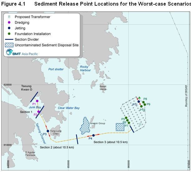
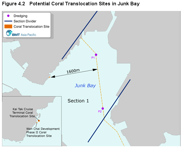
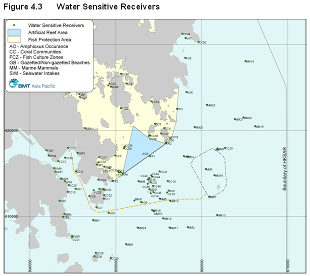
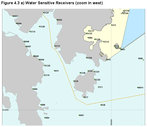
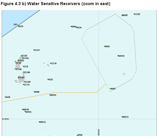
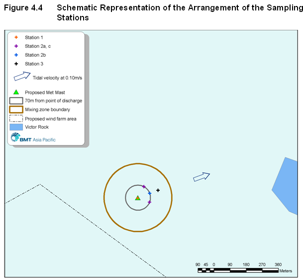
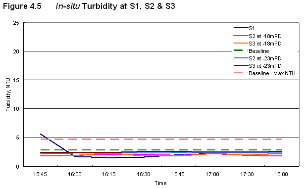
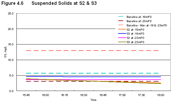
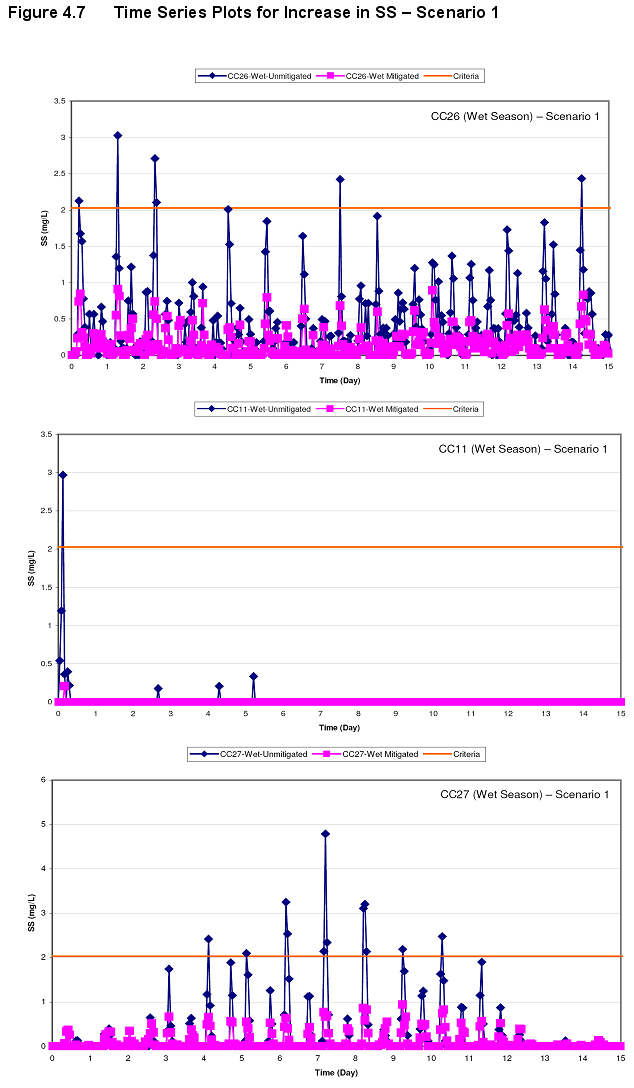
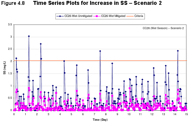
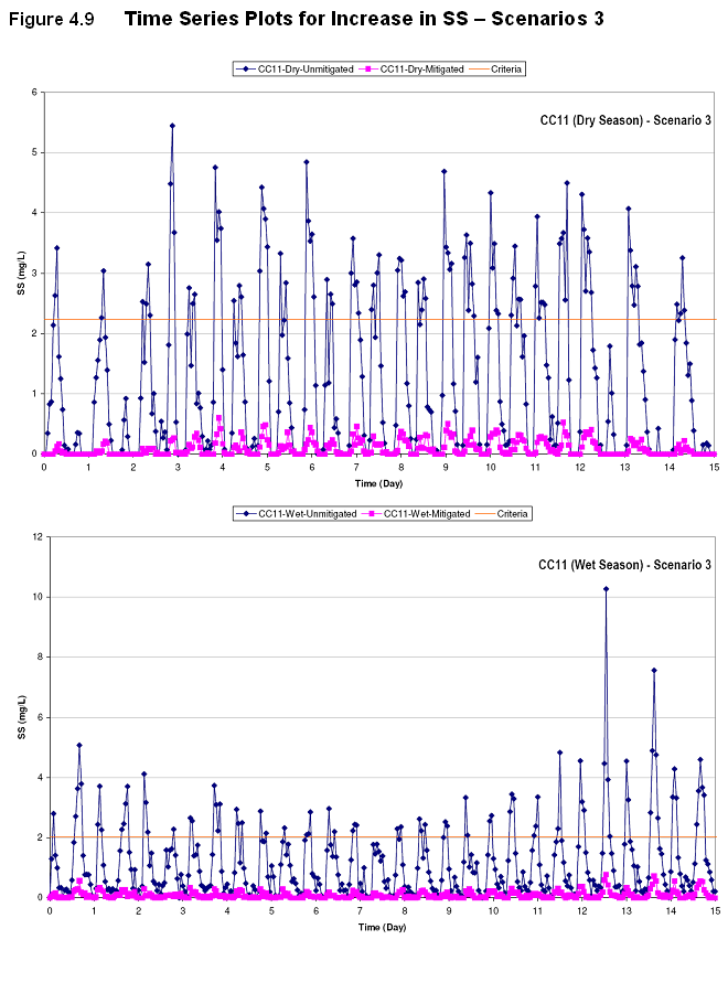
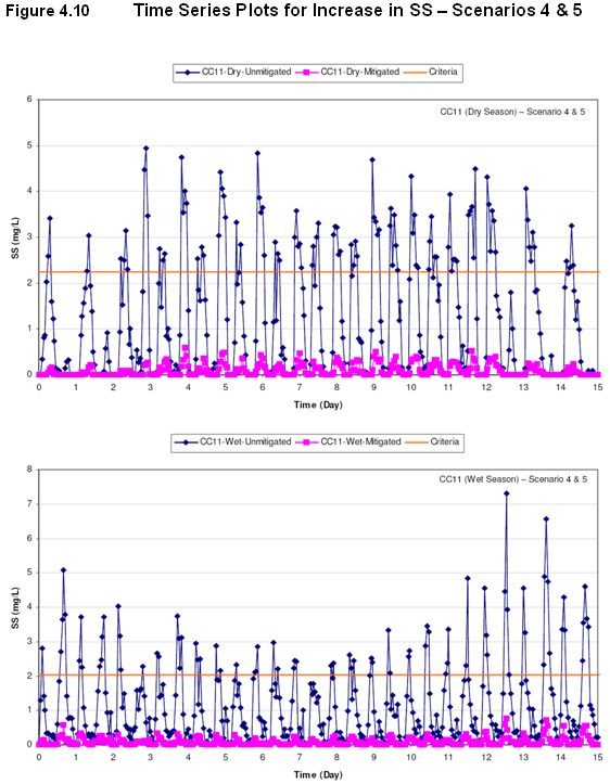
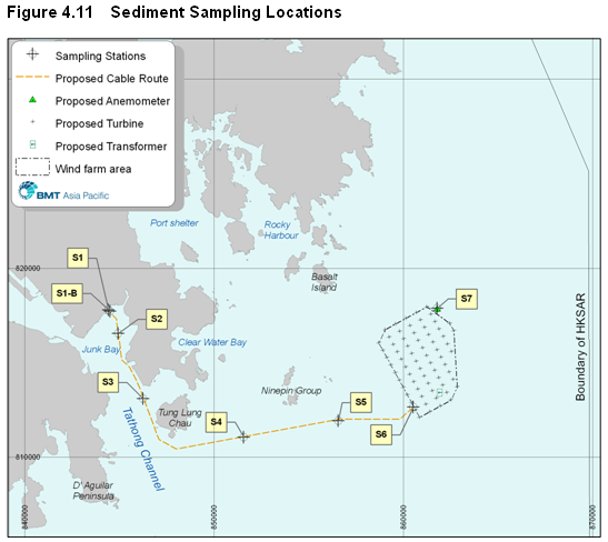
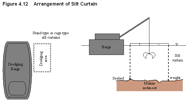
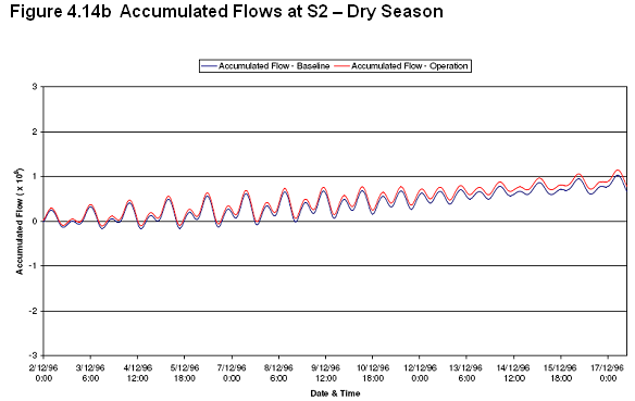
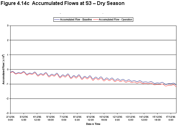
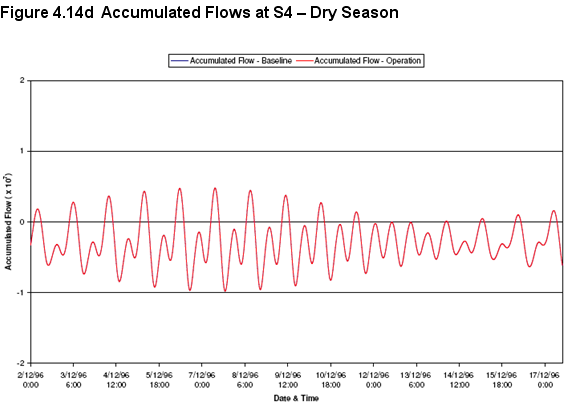
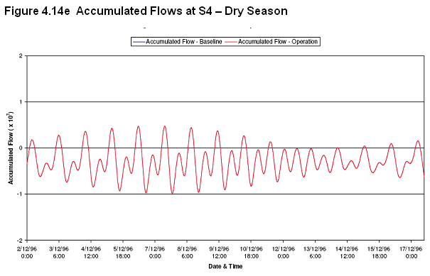
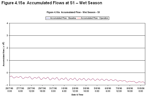
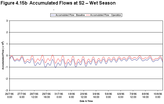
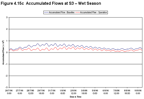
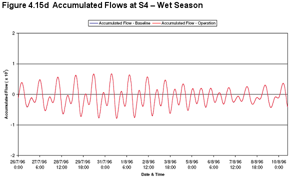
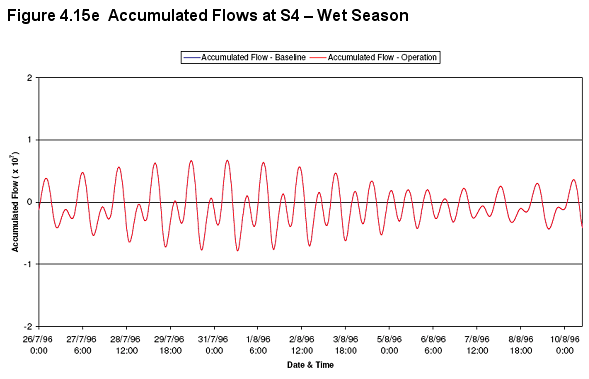
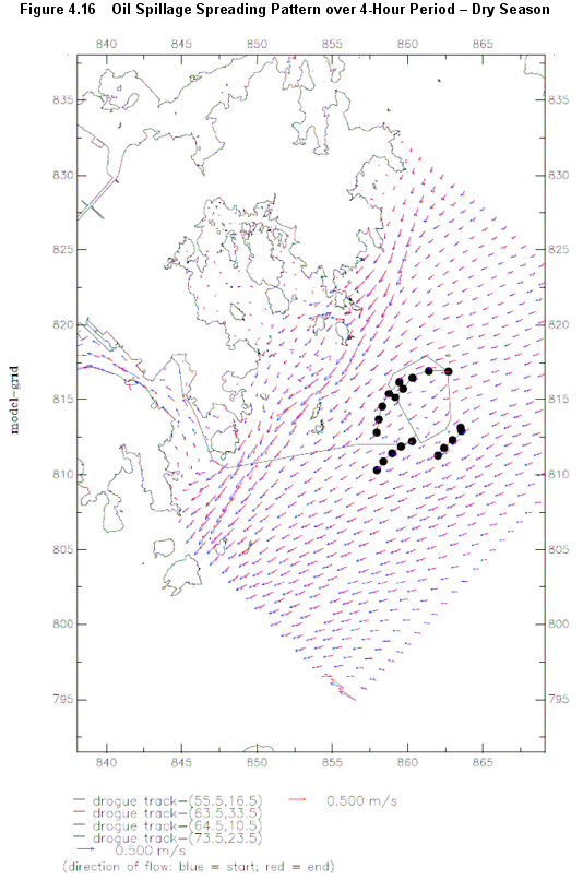
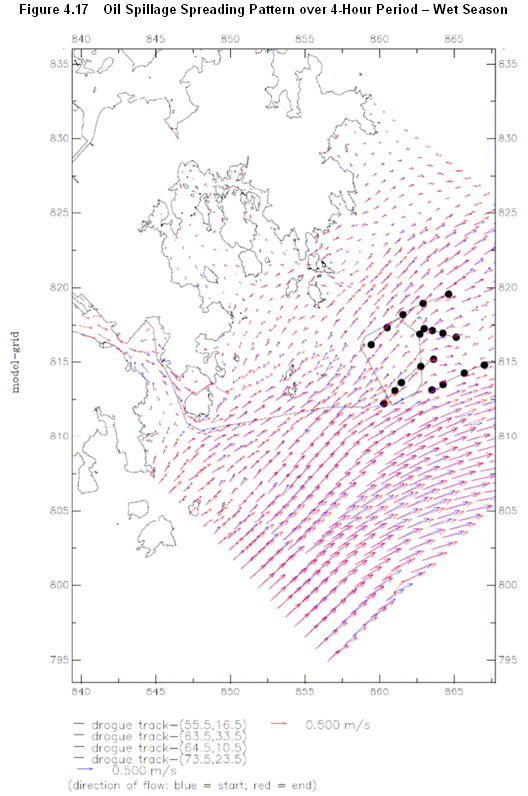
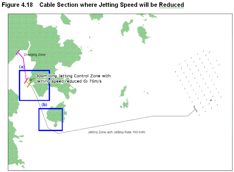
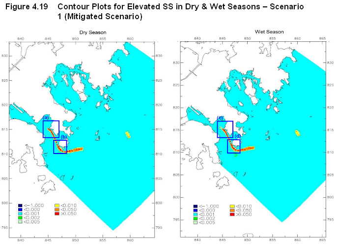
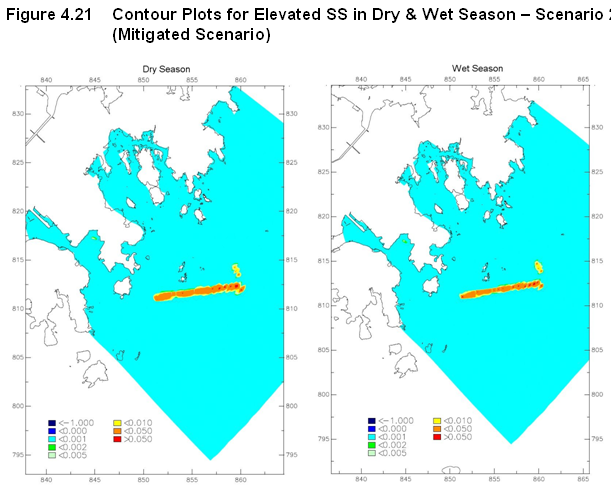
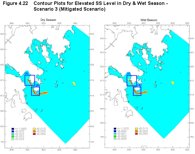
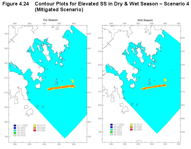
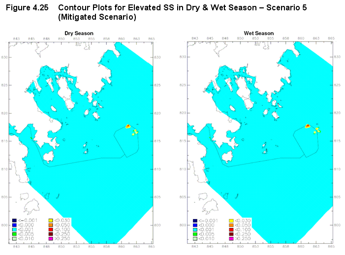