3 Project
Description
3.1 Site
Location and History
Black Point, where the BPPS is situated, is located in the western-most part of the New Territories. It comprises a headland extending from the east (land) to the west (sea) with granitic soil underneath, typical of the Tuen Mun and Castle Peak areas. The major development at Black Point is the BPPS, which is the first natural gas-fired power plant in Hong Kong. The BPPS is located to the north of the headland on reclaimed land. Reclamation in Black Point was completed in 1993 followed by construction of the BPPS and commencement of operation in 1996. BPPS is surrounded by mountain to the east and south while to the immediate north and west is the mouth of Deep Bay.
The proposed location for the Project is within the existing boundaries of the BPPS site and the location for each of the additional CCGT units is illustrated in Figure 3.1. The size of the land reserved for the additional generation units and the associated facilities (the Project Site) is about 40,000 m2. The reserved land has been used for material storage in warehouses and temporary structures. The northern half of the reserved land is not occupied by any buildings or facilities, whereas the southern half is occupied by a single storey warehouse. There are no other facilities or utilities within the reserved land except the surrounding chain link fence.
3.2 Overview
of Project Components
The Project is
comprised of the following key components:
l
Up
to two CCGT units;
l
Cooling
water intake facility; and
l
Cooling
water discharge facility.
The location of these components is shown in Figure 3.2a and Figure 3.2b. Key project details are summarized in Table 3.1.
3.2.1 CCGT
Units
The proposed additional CCGT units (each with an installed capacity of up to 600 MW) and its associated supporting facilities will be located at the Project Site. CCGT is a form of highly efficient power generation technology which combines a gas-fired gas turbine cycle with a steam turbine cycle. For the same fuel input as a simple cycle facility, the CCGT gains the additional output of the steam turbine and thus results in high energy conversion efficiencies and low emissions. This technology is currently being used at the BPPS with a total installed capacity of 2,500 MW (eight units each of 312.5 MW), using natural gas as the primary fuel. The additional CCGT unit(s) will use the most advanced CCGT technology such that its efficiency will be significantly higher than that of the existing units in BPPS.
The basic principle of the CCGT unit is to utilise natural gas (primary fuel) or fuel oil (ultra low sulphur diesel) to produce power in a gas turbine which can be converted to electric power by a coupled generator, and to also use the hot exhaust gases from the gas turbine to produce steam in a heat recovery steam generator. This steam is then used to drive a steam turbine and generator to produce electric power. Both the steam turbine and gas turbine will be coupled to a common generator in a single shaft configuration. An indicative schematic diagram showing the CCGT process is shown in Figure 3.3.
Figure 3.3 CCGT
Process (arrangement for illustration only)
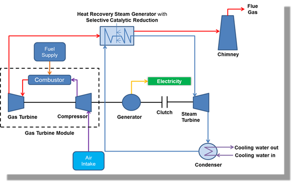
In the CCGT unit, hot exhaust gas from the gas turbine is passed through a Heat Recovery Steam Generator (HRSG) to generate steam to drive the steam turbine. The cooled exhaust gas at around 80�XC will then be emitted to the atmosphere via the stack with a height of 80m to 100m. A Selective Catalytic Reduction (SCR) system is installed in the additional CCGT unit(s) to reduce the NOx emission. Stack emission details are provided in Section 4.
At the end of the steam cycle, once the bulk of the energy is extracted from the system, steam is condensed back into water to begin the cycle anew. In order to complete this phase change, process heat must be removed from the steam such that its temperature drops below the saturation temperature at which process heat transfers to water again. Same as the existing eight combined cycle units in BPPS, a once-through cooling technology will be adopted in the proposed additional CCGT units to reject heat from the steam cycle. This technology is proven to be the most efficient amongst all heat rejection methods considered (including the wet cooling system and air-cooled system) and requires a smaller land-take, thus considered suitable for use for this Project. Water is drawn from the sea and pumped through surface condensers where it picks up waste heat from the steam cycle. The cooling water then returns to the sea via an outfall structure. The design has assumed a cooling water discharge of 950,400 m3 per day for each CCGT unit, with a maximum discharge temperature of 40�XC and total residual chlorine level of 0.5 mg L-1.
Infrastructure for making connection with existing plants and equipment of the BPPS, such as fuel pipes, pipe racks, utility pipes and cables, will also be required for the additional CCGT unit(s).
3.2.2 Cooling
Water Intake Facility
For the first additional CCGT unit (��CCGT Unit No.1), the cooling water intake facility includes a newly constructed cooling water pumping station, enhanced electrochlorination system and underground water pipelines connecting CCGT Unit No.1, as shown in Figure 3.2a. Seawater will be extracted via the existing seawater intake point, flow through the screens in the pumping station and then run through the water pipelines connecting to the CCGT Unit No.1.
Cooling water extracted from the sea will be run through the electrochlorination system in order to produce sodium hypochlorite which is used to treat the seawater before it passes through the cooling water system. Sodium hypochlorite is commonly used in industrial applications to control slime and bacteria formation in the cooling water. This process is continuous and does not rely on any stored chlorine gas or hypochlorite brought from offsite.
Should the second additional CCGT unit (��CCGT Unit No.2��) be installed, a new pumping station, new electrochlorination system and associated building, and intake will be required. The additional water intake point will be located adjacent to the BPPS seawall, nearby the existing cooling water system. New underground water pipelines will be constructed to connect the pump station to the CCGT Unit No.2.
3.2.3 Cooling
Water Discharge Facility
For the CCGT Unit No.1, the cooling water discharge facility includes a new seal pit and the underground water pipelines connecting CCGT Unit No.1 to the existing outfall.
Should CCGT Unit No.2 be installed, a new seal pit and culvert connecting to the existing cooling water outfall or a newly constructed outfall will be required if discharging through the existing outfall is deemed unfeasible. The new outfall will be located to the east of the existing cooling water outfall.
3.3 Construction
Activities
3.3.1 CCGT
Unit No.1 and Associated Facilities
CCGT Unit
The existing warehouse and the surrounding chain link fence will be removed to free up the land for the construction of the additional CCGT units. Typical equipment such as hydraulic crusher and flame cutting will be adopted for the warehouse demolition. In addition, existing facilities/utilities with the Project Site, e.g. the stormwater drainage pipes and manholes, emergency vehicle access (EVA), will be relocated or demolished as appropriate.
For CCGT Unit No.1, four buildings of about 30m tall (final design to be confirmed in detailed design stage) will be constructed within the Project Site to house the power generation equipment and associated facilities, including turbines, generators, transformers, electrical and mechanical equipment, and facilities for fuel, power, service water, etc. Some equipment and installations will be located outside the buildings. Most of the proposed buildings, pipe racks and outdoor equipment are light-weight and hence they will be supported on shallow pad footings or rafts founded directly on the reclaimed land rock fill material. For the heavier structures such as the turbine hall housing, HRSG, stack and the major equipment within which produces significant machinery vibrational loading and have stringent deflection limits, piles will be used for foundation. The deepest excavation required is approximately 3.5m below the existing ground level. Once the foundation work is completed, the buildings will be constructed and the pre-fabricated plant equipment will then be installed on site. The exhaust stack of the CCGT unit is anticipated to be 80m to 100m above the existing ground level.
A new water treatment building will be required for townwater treatment to support the operation of the CCGT unit, which is expected to be built on footings with shallow excavation (approximately 0.8m below existing ground level).
Apart from the buildings and equipment installations, pipe racks in the form of braced steel frames supporting piping and cable trays running in between process skids and equipment will be required. Frames are tied together via beams and are braced in both directions to resist wind load and horizontal piping load. The existing fuel pipes (natural gas and fuel oil) will be suitably modified as needed for connection to the CCGT unit.
The additional CCGT unit will be connected to the existing 400 kV substation in the BPPS through a new underground cable connection. The installation of the 400kV cable will include typical construction method and equipment for shallow trenching (about 2 m deep), e.g. excavation, PVC duct installation, cable laying, backfilling and reinstatement.
Typical construction equipment such as excavators, mobile cranes, welding machines, cutting equipment, powered mechanical hand tools, etc. will be used for site construction and equipment installation.
Cooling Water Intake Facility
Before the actual construction work of the cooling water intake facility commences, facilitating works including some modification to the EVA and relocating underground utilities will be required.
The existing box culvert supplementary seawater intake of the BPPS will be modified to make a diversion connection towards the new pumping station for CCGT Unit No.1. The pumping station will be a reinforced concrete structure largely located below ground. Excavation works of up to approximately 12.1m below the existing ground level is anticipated. An above ground steel structure for supporting the lifting facilities to remove equipment for maintenance is required. Temporary works consisting of excavation and lateral support will be required.
Construction of the underground water pipelines will follow typical open cut construction with trench shoring. In locations where the new pipelines will cross the existing underground water pipelines, the micro-tunnelling method (eg micro-tunnel boring machine (micro-TBM)) will be adopted. The new pipe will be jacked behind a remotely-controlled slurry shield tunnel boring machines. The system simultaneously installs the pipe as soil is excavated and transferred to the ground surface via the slurry excavation system.
The existing electrochlorination facility associated with cooling water treatment will be upgraded to meet the increased need of cooling water due to the construction of CCGT Unit No.1.
Cooling Water Discharge Facility
The cooling water discharge facility includes the construction of a seal pit and underground pipelines connecting CCGT Unit No.1 to the existing cooling water outfall. A new seal pit of reinforced concrete will be constructed by open excavation enclosed by pipe pile or sheet pile. Part of the sloping seawall will be temporarily removed to allow for the construction of a connection between the seal pit and the existing outfall apron. This structure will enable the cooling water of CCGT Unit No.1 to be discharged into the existing outfall.
Construction of the underground water pipelines will follow typical open cut construction with trench shoring. In locations where the new pipelines will cross the existing underground water pipelines, the micro-TBM method will be adopted. The new pipe will be jacked behind a remotely-controlled slurry shield tunnel boring machines. The system simultaneously installs the pipe as soil is excavated and transferred to the ground surface via the slurry excavation system.
3.3.2 CCGT
Unit No.2 and Associated Facilities
CCGT Unit
The construction method and arrangement for CCGT Unit No.2 will be similar to those of CCGT Unit No.1, as described in detail in Section 3.3.1.
Cooling Water Intake Facility
A new dedicated pumping station and intake point will be constructed. The existing intake culvert system is anticipated to reach the capacity limit with the intake of seawater for CCGT Unit No.1. It is unlikely to be feasible to expand the existing culvert system further without generating significant surface swirl or vortices at the inlet. Hence, a separate intake is expected to be required for CCGT Unit No.2. A cofferdam will be constructed along the perimeter of the proposed pump house, the land section and part of the marine section of the intake culvert at the BPPS seawall. The armour rocks on the pile wall footprint will be firstly removed before installing the temporary walling on the sloping seawall. The armour rocks will be temporarily stockpiled on site, in the barge or placed underwater in the vicinity of the excavated seawall for later seawall reinstatement. The walling on the marine side will be installed with piling rig-mounted barge or jack-up barge. Excavation with dewatering and shoring installation will be carried out progressively in the cofferdam. The pump house and part of the culvert will be constructed in-situ under dry condition in the cofferdam with progressive backfilling to the original seawall profile and removal of props. The excavated part of the sloping seawall will be reinstated by backfilling rock fill and armour rocks to the original configuration with derrick lighter.
Before constructing the marine section of the culvert, minor seabed dredging will be required. The intake for CCGT Unit No.2 has to be constructed with adequate submergence below the sea level, with low tide conditions taken into account, for stable hydraulic performance of the intake and for avoidance of adverse hydraulic effect (e.g. vortices) to the waters nearby and detrimental cavitation in the cooling water pumps. Construction of the intake to the required depth below seabed would require dredging of marine sediment. Figure 3.2b shows the indicative dredging location for the construction of intake, which covers an area of about 100m x 100m, with an estimated volume of around 20,000 m3. Dredging will be carried out using closed grab dredger plus hopper barges with a dredging rate limited to 4,000 m3 per day. Dredged marine sediment will be transported by hopper barge and tug boats to and disposed of at the sediment disposal area as allocated by the Marine Fill Committee (MFC) of the Civil Engineering Development Department (CEDD). For construction of the marine section of the culvert, rock fill/sand fill and then granular bedding material will be laid by derrick lighter on the dredged seabed for foundation of the culvert. The laid foundation will be tamped by precast concrete blocks manoeuvred by derrick lighter. Precast segments will then be transported and lowered into the water by derrick lighter or crane barge to the appropriate position and orientation and connecting together. Rock fill/sand fill will be backfilled on two sides of the culvert segments and the armour rocks will be laid over the culvert structure for protection against scouring, ship impact or drop anchor as necessary.
Construction of the underground water pipelines from the pumphouse to CCGT Unit No.2 will follow typical open cut construction with trench shoring.
The existing electrochlorination facility associated with cooling water treatment will be upgraded to meet the increased need of cooling water due to the construction of CCGT Unit No.2. Additional electrochlorination building will be built on footings with a shallow excavation of approximately 0.8m below existing ground level using an open cut method. The existing vehicular access road adjacent to the existing electrochlorination facility will be realigned and extended to enclose the facility.
Cooling Water Discharge Facility
The use of existing cooling water outfall system of the BPPS for CCGT Unit No.2 has been considered. The discharge facility would include the construction of a new seal pit to the east of the existing seal pits, and a connection to the existing outfall similar to the one for CCGT Unit No.1 will be required. A new discharge pipe connecting CCGT Unit No.2 to the outfall will be constructed underneath Chimney Road using a micro-TBM where pipes will be jacked underneath the road and the current discharge pipes. At locations crossing the existing cooling water pipes, an underpass will be created (see the methodology described under CCGT Unit No.1).
However, if the above arrangement is not feasible, a new cooling water outfall to the east of the existing outfall structure will be required. In addition to the new seal pit mentioned above, a length of pipe or culvert will be required to connect the seal pit to the new outfall.
Minor seabed dredging will be required for the construction of the new outfall. The new outfall requires placement of sizeable precast seawall blocks and rock blanket on the seabed to dissipate the kinetic energy of the discharge from the outfall and hence minimising scouring effect on the seabed in the vicinity of the outfall. In order to minimise changes to the surrounding flow regime, placement of the rock blanket is required to match the existing seabed profile as far as possible. The seawall blocks and rock blanket, due to its substantial self-weight, will have to be founded on uniform rigid ground to avoid uneven settlement and hence poor performance in flow energy dissipation. Dredging of marine sediment underneath the outfall apron is thus necessary to avoid gradual wash-out of sediment by the constant high cooling water discharge which could lead to dislocation of the outfall. Minor seabed dredging (over an area of about 100m x 100m, with an estimated volume of around 20,000 m3) as shown in Figure 3.2b will be carried out near the proposed new outfall location using closed grab dredger and hopper barges. The dredged marine sediment will be transported by hopper barge and tug boats to and disposed of at sediment disposal area as allocated by the MFC of CEDD.
To construct the new outfall, a section of the existing concrete crest wall will be removed and then a pipe-pile or sheet-pile wall will be constructed at the same location. Trenches will be excavated with shoring immediately behind and perpendicular to the temporary walling for installation of ground anchors connecting to the temporary walling. The trenches will be progressively backfilled with compacted rock fill and with removal of shoring. The armour rock will be removed and underlying rock fill excavated by derrick lighter from the existing sloping seawall to form the required underlying profile for the outfall apron. The ground behind the excavated seawall portion will be retained and protected against waves by the temporary walling with ground anchors. Seawall blocks, rock fill and filter layer will be progressively installed onto the excavated seawall by derrick lighter. Temporary water cut-off measures will be placed surrounding the area where the reinforced concrete outfall apron will be constructed in dry condition by cast in-situ method. The excavated part of the sloping seawall on the two sides of the outfall apron will be reinstated by backfilling rock fill and armour rock to the original configuration with derrick lighter. The armour rocks will be laid by derrick lighter on the dredged seabed to form the riprap apron of the outfall.
3.4 Operation
Activities
The additional CCGT unit(s) will commence operation in phases upon completion of construction and testing and commissioning. The units will normally be operated except closing for general maintenance works.
To fuel the additional CCGT unit(s), the import of natural gas to the BPPS is anticipated to be increased. During operation of the CCGT unit(s), emissions (e.g. stack emissions, cooling water and heat discharge) from the BPPS will comply with the relevant license requirements in accordance with statutory requirements, including the Air Pollution Control Ordinance, Water Pollution Control Ordinance, etc.
For the SCR process in the additional CCGT unit(s) for NOx reduction, it will use ammonia gas to convert NOx emissions to elemental nitrogen and water in the presence of catalysts, which is the same as the existing operations at the CPPS. The ammonia gas used in the process will be from a urea-to-ammonia conversion system. As the catalysts are not chemically modified in the process, their service life is generally very long and rejuvenation of catalysts is only required after 4 to 6 years of use. No solid or liquid by-products will be generated in the SCR process. Urea will be delivered to BPPS by trucks. Urea handling system and urea-to-ammonia conversion system will be used to support the operations of the SCR of the additional CCGT unit(s).
Should CCGT Unit No.2 be implemented, maintenance dredging near the cooling water intake and discharge facilities may be required, depending upon the current condition at the sites. The timing and extent of dredging will be planned based on findings of regular geophysical surveys. It is expected that future maintenance dredging could be conducted at a frequency of 4 to 5 years and the dredged volume will be around 33% of that in the capital dredging (i.e. 6,600 m3) for each facility. Similar to the arrangement for project construction, sediment sampling, testing, handling and disposal procedures as stipulated by the Practice Notes for Authorised Persons, Registered Structural Engineers and Registered Geotechnical Engineers will be followed and complied with.
3.5 Project
Summary
Table 3.1 presents a summary of project details. The two proposed additional CCGT units and associated facilities would be implemented in stages. All land-based construction activities will be undertaken within the BPPS. No marine works will be required for the construction of CCGT Unit No.1. The construction of CCGT Unit No.2 is expected to generate no more than 40,000 m3 (in situ volume) of marine sediments for off-site disposal.
Table 3.1 Summary of Key Project Details
|
Item |
Detail |
|
CCGT Unit No.1 and Associated Facilities (Figure 3.2a) |
|
|
Project Scope |
Ÿ Clearance activities within the Project Site, including alternation of temporary warehouse Ÿ Civil works and electrical / mechanical works for installation of one CCGT unit (with an installed capacity of up to 600 MW) , its associated auxiliary equipment and supporting facilities which include four buildings of about 30m high (subject to final design) to house power generation equipment such as turbines, generators, transformers, etc., outdoor pipe racks and equipment, an exhaust stack of about 80m to 100m above ground, infrastructures for making utilities connections (e.g. 400 kV cables, electrical and control cables, pipes for fuel gas, fuel oil, water supplies, auxiliary gas supplies, etc.) from existing plant equipment in BPPS to the CCGT unit and necessary works for enhancement/expansion of existing plant equipment. Ÿ Installation of cooling water intake facility which includes a newly constructed cooling water pumping station, enhanced electrochlorination system and underground water pipelines. Ÿ Installation of cooling water discharge facility which includes underground water pipelines, a new seal pit, and connection between the seal pit and the existing outfall.
|
|
Construction Activities |
Ÿ Relocation or demolition of existing facilities/ utilities within the Project Site by typical equipment such as hydraulic crusher, flame cutting, excavators, etc. Ÿ Site construction, excavation, trenching, modification of existing box culvert supplementary seawater intake, and equipment installation by typical equipment such as excavators, mobile cranes, welding machines, cutting equipment, powered mechanical hand tools, micro-tunnel boring machine, etc.
|
|
Operational Activities |
Ÿ CCGT unit and its associated supporting facilities will normally be operated except closing for general maintenance works. Ÿ Discharge of cooling water.
|
|
CCGT Unit No.2 and Associated Facilities (Figure 3.2b) |
|
|
Project Scope |
Ÿ Clearance activities within the Project Site, including alternation of temporary warehouse Ÿ Civil works and electrical / mechanical works for installation of one CCGT unit (with an installed capacity of up to 600 MW) , its associated auxiliary equipment and supporting facilities which include four buildings of about 30m high (subject to final design) to house power generation equipment such as turbines, generators, transformers, etc., outdoor pipe racks and equipment, an exhaust stack of about 80m to 100m above ground, infrastructures for making utilities connections (e.g. 400 kV cables, electrical and control cables, pipes for fuel gas, fuel oil, water supplies, auxiliary gas supplies, etc.) from existing plant equipment in BPPS to the CCGT unit and necessary works for enhancement/expansion of existing plant equipment. Ÿ Installation of cooling water intake facility which includes a newly constructed cooling water pumping station, new electrochlorination facility and building, a new intake culvert, and underground water pipelines. Ÿ Installation of cooling water discharge facility which includes a newly constructed seal pit, a new outfall culvert, and underground water pipelines.
|
|
Construction Activities |
Ÿ Relocation or demolition of existing facilities/ utilities within the Project Site by typical equipment such as hydraulic crusher, flame cutting, excavators, etc. Ÿ Site construction, excavation, trenching, and equipment installation by typical equipment such as excavators, mobile cranes, welding machines, cutting equipment, powered mechanical hand tools, micro-tunnel boring machine, etc. Ÿ Minor marine dredging for cooling water intake and discharge facilities by one closed grab dredger supported by hopper barge and tug boat Ÿ Seawall cofferdam construction, installation of cooling water intake and outfall culverts and temporary seawall removal and reinstatement by piling rig-mounted/ jack-up barge, derrick lighter and crane barge
|
|
Operational Activities |
Ÿ CCGT unit and its associated supporting facilities will normally be operated except closing for general maintenance works. Ÿ Discharge of cooling water. Ÿ Maintenance dredging near the cooling water intake and discharge facilities, expected to be at about once every 4 to 5 years.
|
|
Area of Seabed Affected by the installation of Cooling Water Intake and Discharge Facilities
|
Ÿ Two areas of about 100m x 100m each |
|
Length of Existing Artificial Seawall affected by the installation of Cooling Water Intake and Discharge Facilities
|
Ÿ ~150 m of seawall to be reinstated as sloping artificial seawall Ÿ ~50 m of seawall to be transformed as intake/ outfall culverts |
|
Dredging Volumes (in situ volume) from the installation of Cooling Water Intake and Discharge Facilities
|
Ÿ From two areas of about 20,000 m3 each |
|
Dredging Volumes (in situ volume) from Maintenance Dredging
|
Ÿ ~6,600 m3 for each facility |
3.6 Tentative
Implementation Programme
Subject to obtaining HKSAR Government approval of the Project and a final investment decision on the Project being taken by CLP/CAPCO, it is anticipated that the construction of the Project would be implemented in stages for CCGT Unit No.1 and CCGT Unit No.2. An indicative construction programme is shown in Figure 3.4.
Figure 3.4 Preliminary
Construction Programme of the Project
Assuming that the construction of CCGT Unit No.1 can commence from the second half of 2016, site clearance work will commence immediately while the civil work will start Q3 of 2016 till the Q2 of 2018, lasting for about 24 months. Plant and equipment will be delivered to the site and the installation work is expected to commence in parallel. The equipment installation work will last for about another 18 months followed by commissioning and reliability test. Commercial operation of CCGT Unit No.1 is anticipated by the end of 2019.
The construction of CCGT Unit No.2 will follow a similar programme, but the commencement date for construction will be after 2019.
3.7 Concurrent
Projects
The Project
will be located within the existing BPPS site. The following committed or
planned projects in the surrounding areas may potentially interface with the
construction and operation of this Project:
l
Engineering Feasibility Study for Industrial Estate at
Tuen Mun Area 38
(EPD Study Brief ESB-277/2014): this project includes the development of an
Industrial Estate with temporary loading and storage of petrochemical feedstock
site and other road modification works in Tuen Mun Area 38 and is currently under EIA stage. This
potential concurrent project is more than 3 km away from the Project Site, and
its construction period is tentatively scheduled from 2019 to 2023.
Details of this project are not publicly available at the time of preparation
of this EIA;
l
West New Territories (WENT) Landfill Extensions
(Register No.: AEIAR-147/2009): this landfill extension is approximately 2 km
away from the Project Site, and is targeted for commissioning and operation in
2019. It is currently under a Design and Construction Consultancy Study;
l
Pyrolysis Plant at EcoPark
(EPD Study Brief ESB-259/2013): this project consists of four 5-tonne pyrolysis
furnace systems, with each system having a handling capacity of 5 tonnes of
waste plastics per day. It is currently under the EIA stage and the
implementation timing is uncertain at this stage. It is located
approximately 4.5 km away from the Project Site;
l
Development of the Integrated Waste Management
Facilities Phase 1 (Register No.: AEIAR-163/2012): this project to
construct and operate a modern facility for managing municipal solid waste
through an advanced thermal incineration process. It comprises an
incineration plant, a mechanical treatment plant, and ancillary facilities,
which may be constructed at the Tsang Tsui Ash Lagoon
in Nim Wan, Tuen Mun. The construction programme at this site is yet
to be confirmed;
l
Planning and Engineering Study for Tuen
Mun Areas 40 and 46 and the Adjoining Areas
(EPD Study Brief ESB-255/2012): the study aims to investigate the potential for
re-planning Tuen Mun Areas
40 and 46 and the adjoining areas for uses such as commercial, office and hotel
uses, logistics uses, high technology, industry uses, residential use,
etc.. According to the latest information from the project website, the
feasibility study commenced in May 2013 and is anticipated for completion in
2015; however the future development proposal is yet to be determined;
l
Potential Reclamation at Lung Kwu
Tan: this site is located along the coastal waters of
Lung Kwu Tan and Lung Kwu Sheung Tan. With an area of about 200 �V 300 ha, this
proposed site would potentially be used for residential development ([1]).
Details of its implementation programme are uncertain at this stage;
l
Enhanced Ash Utilisation and Water Management
Facilities at Castle Peak Power Station (CPPS)
(EP-441/2012): This project involves the re-construction of the two existing
water lagoons at CPPS by lowering their base slabs and the construction of a
new one to increase the storage capacities of the water lagoons at CPPS.
The water lagoons are used for temporary storage of stormwater runoff collected
from the coal stockyard and process water from the operation of the CPPS which
in turn can be reused for the operation of the CPPS. The project is
expected to be constructed between 2017 and 2020. It is more than 3 km
away from the Project Site; and
l
Decommissioning of West Portion of the Middle Ash
Lagoon at Tsang Tsui, Tuen Mun (Register No.: AEIAR-186/2015): This project
involves the decommissioning of the pulverised fuel ash (PFA) lagoon at the
west portion of the Middle Ash Lagoon at Tsang Tsui, Tuen Mun, which was operated by
CAPCO for the placement of water and PFA. The decommissioning will
provide buildable land for future developments by the HKSAR Government. A
columbarium has been proposed to be built at the site. The tentative
decommissioning period would be from early 2016 and the construction of
columbarium is targeted for completion by 2018/2019. It is about 1 km
away from the Project Site.
In addition,
the following existing operations in the Black Point and Castle Peak areas may
also interact with the construction and operation of this Project:
l
Sludge Treatment Facilities
(STF) (Register No. AEIAR-129/2009): the STF is located about 1.5 km away from
the Project Site. It serves to treat dewatered sewage sludge from the
public sewage treatment works by high temperature incineration and reduce the
volume of sludge requiring final disposal at landfill by up to 90% through the
thermal process ([2]);
l
Permanent Aviation Fuel Facility (PAFF) for Hong Kong
International Airport (Register No.: AEIAR-107/2007): the PAFF is located
about 4.5 km away from the Project Site. It consists of a tank farm
providing jet fuel to the Hong Kong International Airport via submarine fuel
pipelines;
l
Castle Peak Power Station (CPPS):
CPPS is a coal-fired power plant located in Tap Shek Kok in Tuen Mun,
approximately 4 km away from the Project Site. The operation of CPPS is
regulated under a Specified Process licence;
l
Green Island Cement Plant: this site
produces cement and is operating under a Specified Process licence. It is
more than 4 km away from the Project Site; and
l
Shiu
Wing Steel Mill: this site manufactures steel bars is operating under
a Specified Process licence. It is more than 4 km away from the Project
Site.
The above concurrent projects may pose cumulative impact with the construction and/or operation of the Project. The cumulative impacts from the above concurrent projects are addressed in the technical assessments in this EIA if these projects are located within the study area for the respective technical aspects.
([1]) Agreement No. CE 14/2013 (CE) Cumulative Environmental Impact Assessment Study for the Three Potential Nearshore Reclamation Sites in the Western Waters of Hong Kong - Investigation - Executive Summary (Final) (2013). Retrieved October 6, 2015 from Civil Engineering and Development Department, Web site: http://www.cedd.gov.hk/eng/landsupply/doc/Executive%20Summary%20on%20Final%20Report(S2)b.pdf
([2]) Source of information: http://www.epd.gov.hk/epd/english/environmentinhk/waste/prob_solutions/WFdev_TMSTF.html