3
What is Required to Bring LNG to Hong Kong
3.1
The LNG Supply
Chain ([1])
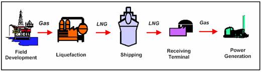
The process of LNG production involves the
transport of the natural gas from the production fields via pipeline to a
liquefaction plant. Prior to
liquefaction the gas is first treated to remove contaminants, such as carbon
dioxide, water and sulphur to avoid them freezing and damaging equipment when
the gas is cooled to -162°C. The
liquefaction plant is similar to a large refrigerator with compressors,
condensers, pressure expansion valves and evaporators.
The LNG produced from the refrigeration
process is piped to specially designed LNG storage tanks. Both the piping and tanks are insulated to
maintain the low temperature and constructed using special materials to contain
the cryogenic liquid. LNG is then drawn
from the storage tanks and loaded onto specially equipped LNG carriers. The carrier delivers LNG to a receiving/regasification terminal where it is stored in LNG tanks and
converted back to a gaseous state prior to being dispatched/piped to the
end-user such as a power plant when needed.
The whole process is referred to as the
LNG Supply Chain and is illustrated in Figure 3.1. The only
elements of the supply chain that will take place in
Near the end of the supply chain is the
receiving terminal. The key components of the proposed LNG terminal, including
marine jetty facilities for unloading LNG, special tanks for LNG storage,
process equipment for the regasification of LNG,
utilities and other infrastructure, are depicted in the process overview (Figure 3.2). Site specific
details of the LNG terminals at the two selected sites are presented in Part 2- Section 3 and Part 3-Section 3.
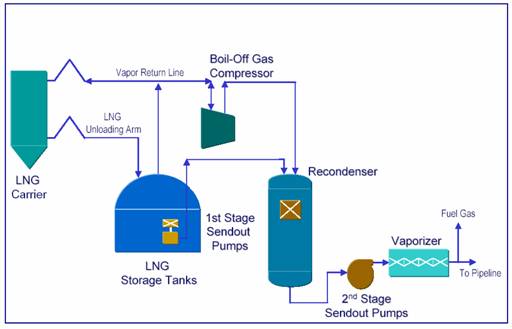
Figure 3.2 LNG
Terminal Key Components and Process Overview
A receiving terminal, similar in size to
this project, will typically require approximately 30 - 40 ha of land to locate
the necessary infrastructure, which includes the following:
·
Jetty
and unloading arms
·
Process
Area
·
LNG
Tanks
·
Low
Pressure and High Pressure pumping systems
·
Vaporisation
(Regasification) Area
·
Vents
(low pressure and high pressure)
·
Maintenance
Workshop
·
·
Guard
House
·
Utility
Area
·
Control
Room
3.2.1
Marine Facilities
A jetty and unloading arms are required to
transfer the LNG from the carrier to the terminal. The length of the jetty is defined by
specific site conditions, and the maximum length overall of the LNG carrier
that will deliver the required cargo volume.
In addition, a turning circle of sufficient size and depth is required
to allow for turning the LNG carrier either prior to berthing or on departure
after completion of unloading.
The unloading arms are moved with a
remote-controlled hydraulic system located on the berth. When they are lined up with the LNG carrier,
the two are then secured by bolts or quick connect couplings. Five arms are typically installed, three for
unloading LNG, one for return vapours and one spare that can be used for either
service. After connection is completed,
the communication cable is connected to shore and the emergency shutdown system
is tested.
After the unloading arms are cooled, the
LNG will be transferred from the carrier to the storage tanks using the
carrier's pumps. The discharge of LNG
from the carrier takes approximately 18 hours.
In addition, approximately 3 hours are required for mooring, cool down,
connecting unloading arms, and cargo measurement, and approximately 3 hours for
cargo measurement, arm purging, disconnecting arms, and unmooring.
Following berthing, the LNG is pumped
ashore via the carrier’s pumps through unloading arms to a cryogenic pipeline
and on to the storage tanks. For this
project, an above-ground, full containment design has been selected. The LNG will be stored near atmospheric
pressure and in full-containment LNG tanks that typically consist of the
following:
·
Primary
inside tank - made of a "cryogenic material" such as 9% Nickel steel,
aluminium alloy or reinforced pre-stressed concrete; it is now common practice
to use 9% Nickel steel for the inner tank in LNG service;
·
Insulation
– loose insulation material (such as perlite)
surrounding the inner nickel steel tank (sides, floor and roof);
·
Vapour
barrier tank – made of carbon steel to contain the insulation system and vapour
pressure of the primary tank;
·
Outer
tank – reinforced, pre-stressed concrete designed to independently store both
the LNG liquid and vapour should the inner wall fail; and,
·
Domed
roof – reinforced, pre-stressed concrete.
An
illustration of typical full containment tank is presented in Figure
3.3.
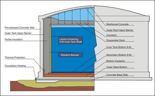
Figure 3.3 Example of a Full Containment LNG Storage Tank
LNG tanks are specially designed to contain
the LNG at its cryogenic temperature of approximately -162 °C near atmospheric pressure. After initial transportation planning, which
includes detailed shipping and storage simulation modelling of Black Point
Power Station’s requirements with regard to LNG volume, minimum inventory, and
potential sources of supply and ship sizes, a LNG storage facility comprising
two tanks of 160,000 to 180,000 m3 each is planned. Space will be provided for a third tank for
future expansion (180,000 m3 tanks may be considered). This EIA is based on three LNG storage tanks,
i.e., a total capacity of 540,000m3.
The LNG tanks have a top entry point for
both the loading and unloading operations.
Two submerged send-out pumps per tank will be suspended from the top of
the tank and pump the LNG out of the tanks.
All tanks will be designed to simultaneously send out (to the vaporiser
units) and to receive LNG (from unloading LNG carriers). The tanks will be fitted with a low-pressure
vent, which will provide storage tank overpressure protection if the tank
pressure exceeds the maximum operating limit of the LNG storage tank design
pressure.
3.2.3
Other Major Process Facilities
Vapour Handling System and Boil-off Gas
(BOG) Condenser
Boil-off gases (BOGs)
are produced during normal terminal operations as a result of inevitable heat
transfer arising from the storage and handling of LNG. This BOG is captured and sent to the BOG
compressor for re-condensing (liquefying).
A second BOG compressor will serve as a backup or a spare. The BOG condenser outlet liquid stream flows
to the HP LNG Booster pumps to raise the LNG to the send-out pressure before
feeding the LNG to the LNG vaporisers.
LNG is heated and converted back to gas in the vaporiser unit.
Stored LNG will need to be re-gasified in order for it to be transported by gas pipeline
to the point of use. This will be
accomplished via LNG Vaporisers, which will either utilise piped seawater (in
open rack vaporisers) or hot combustion gases (in submerged combustion
vaporisers) to raise the temperature of the LNG to ambient, thereby causing it
to re-gasify.
Once the LNG is vaporised the gas is then regulated for pressure and
piped to the consumer.
Open Rack Vaporisers – The seawater will pass through a series
of screens to remove debris to prevent blockage or damage to the seawater pumps
before entering the open-rack vaporises (ORVs). In ORVs, seawater
flows over the exterior of the vaporiser panels, which internally channel an
upward flow of high-pressure LNG (HP LNG).
LNG will then be vaporised by exchanging heat with seawater in the ORV’s. The seawater
flows over the panels to a trough below and is then discharged back to the sea
via a submarine outfall.
Submerged Combustion Vaporisers - In Submerged Combustion Vaporisers (SCVs), LNG flows through tubes that are submerged
in a heated water bath. LNG will then be
vaporised.
Pumps
Each LNG storage tank will be configured
with two in-tank LNG send-out single-stage centrifugal pumps. LNG send-out pumps discharge to the HP LNG
booster pumps. The HP LNG booster pumps
will be designed to meet the required send-out pressure for the pipeline
option. Six HP LNG booster pumps
including one spare will be used in the expansion case.
Gas Meter
Stations
The outlet gas from the vaporisers will be
metered at metering stations and sent to the gas pipeline at South Soko (
Fuel Gas System
The fuel gas system including high- and
low-pressure fuel gas systems will provide sufficient fuel gas for the various
terminal users such as power generation, heating, and any SCV’s
in operation. Vaporised high pressure
natural gas will be used for on-site power generation, while the low-pressure
fuel gas system will provide sufficient natural gas for the various terminal
users such as SCV, heating the gas to the gas turbines for power generation
when needed, and other heating requirements.
BOG and/or letdown vaporised LNG will be used for low-pressure natural
gas at approximately 5.5 barg (80 psig).
The LNG terminal is designed for the safe
handling of vapour discharges from the system, such as from relief valves,
which are sent to the vent header and then to the separator before going to the
vent stack. There are two vent systems,
a high-pressure (HP) vent stack and a low-pressure (LP) vent stack.
The LP and HP vent system is designed for
the following possible situations:
·
All
the equipment will be provided with pressure relief devices. In the case of over-pressuring, the relieved
vapour will be vented to the vent stacks which are designed to safely route the
gas away from hazardous areas.
·
LNG
tank roll-over ([2]) and BOG from a sudden drop in barometric
pressure.
·
In the
event of total facility power failure, the LNG send-out and the unloading
operations will be stopped and the boil-off gas will be routed to the LP and HP
vent systems.
3.2.4
Utilities and Ancillary Facilities
Nitrogen
Nitrogen is required at the terminal for
equipment purging and maintenance purposes.
Adequate on site nitrogen generation and storage for liquid nitrogen
will be provided at the terminal. The
nitrogen generation and storage tank size are based on normal purging and
maintenance requirements. For start-up
and/or LNG tank purging, additional nitrogen will be made available on site by
providing liquid nitrogen tanks from supply vehicles.
Air
Instrument and utility air for use within the terminal are
produced on site. Two air compressors on
lead-lag demand, one dual and regenerative instrument air drying system,
separate instrument and utility receivers, and piping headers will be
provided.
Power Generation
The power supply for the LNG terminal can
either be generated on-site using a gas turbine or imported. A battery supplied UPS (Uninterrupted Power
Supply) system powers the Emergency Shutdown (ESD) and gas and fire systems to
ensure the operation of critical systems in the unlikely event of a complete failure
of the power.
Waste and Wastewater Treatment
A system will be
provided for the treatment of wastewater.
A s
Solid wastes will be
collected and sent to the appropriately licensed disposal facility.
Communications
The terminal will be outfitted with
up-to-date communications equipment capable of maintaining contact with the LNG
carriers scheduled to offload at the terminal and with the standby tugs.
3.2.5
Buildings
The following permanent buildings will be
provided on site for the operational phase:
·
·
·
Maintenance/Warehouse
Building - equipment and spare parts will be stored in this building.
·
Switchgear/MCC
Building - will house switchgear, motor control centres, panel boards, UPS,
batteries and battery charges, lighting transformers, PLC panels for
switchgears, MCCs, generator control panels and other
equipment. Power distribution
transformers will be located on the roof of this building.
3.2.6
Protective
Systems
Gas Detection, Alarm, Firefighting
and ESD Systems
A centralised spill, fire and combustible
gas alarm and control system will provide input to an information management
system. Automatic detection devices,
manual alarms and audible and visual signalling devices will be strategically
located throughout the terminal.
Automatic detection devices will include flame, fire and heat, smoke,
low temperature and combustible gas detectors.
CCTV monitors will be installed to allow visual surveillance of critical
facilities from the central control room.
An emergency shutdown system (ESD) will be incorporated in the design of
the terminal and provide the operators with the capability of remotely shutting
down the entire or selective portions of the terminal. The unloading arms will also be equipped with
Powered Emergency Release Couplers (PERCs). The PERC maintains containment integrity and
prevents damage to the unloading arms in the event of an emergency.
Security
Security will be designed to prevent
unauthorised access and to ensure the safety and integrity of the
facilities. The site will be provided
with a perimeter fence and access will be restricted. Perimeter lighting will also be provided.
LNG carriers have insulated cargo tanks and are of double-hull
design. The double hull provides the
location for the segregated ballast and provides optimum protection for the
integrity of the cargo tank containment in the unlikely event of collision or
grounding. There are two types of LNG
carriers: Moss and Membrane ([4]) (Figure
3.4).
Currently, a typical LNG carrier has a
Length Overall (LOA) of approximately 285 m, a 43 m beam and a 12 m draft, with
a cargo capacity of around 145,000 m3. The LNG is transported in the tanks near
atmospheric pressure and the boil-off gas can be used to supplement liquid fuels
for propulsion. LNG carriers of larger
capacities are under development ([5]).
LNG carriers of larger capacities, up to 215,000 m3 are
currently being built for other projects and a carrier of this class has been
selected for this EIA Study.
As illustrated in Figure
3.4 for Moss carriers four or five spherical tanks
contained in the hull, with a substantial proportion of each tank above the
weather deck. In a membrane design the
larger proportion of each tank is below the weather deck (Figure 1.3 ). Both carrier
types are commonly utilised for LNG transit with no significant operational
difference between them. Consequently, a
navigable water depth of approximately -15m PD will be required for the
vessels’ transit to either Black Point or
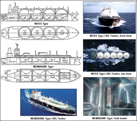
Figure 3.4 Moss and Membrane LNG Carriers
Prior to entry into
The
world’s first large scale LNG trade began in 1964, with the
In
terms of consumption of LNG, the largest importer by far is
In
In the
The LNG industry has an excellent safety
record ([8])
in all aspects of shipping,
storage and regasification. This is due to both the high technical
standards that are used in the design, construction and operation of LNG facilities
and carriers and also the physical properties of LNG, as described in Section 2.2. In part, the safety record is a result of the
adoption worldwide of a series of standards, codes and regulations ([9]).
3.5.1
Shipping
LNG shipping has an outstanding safety
record ([10]).
LNG has been safely transported across the world’s oceans over the last
40 years. In that time there have been
over 45,000 LNG carrier voyages covering more than 90 million miles
without any loss of life in port or while at sea ([11]).
At the end of 2005, there were approximately 190 LNG carriers in the
world fleet.
LNG carriers frequently pass through areas
and ports that have high traffic densities, such as in
3.5.2
Safety Considerations in LNG Carrier
Design and Operation
LNG carriers have insulated cargo tanks
and are of double-hull design. The
double hull provides the location for the segregated ballast and provides
optimum protection for the integrity of the cargo tank containment in the event
of collision or grounding. LNG carriers
also have safety equipment to facilitate ship and cargo system handling. The ship-handling safety features include
sophisticated radar and positioning systems that enable the crew to monitor the
carrier’s position, traffic and identified hazards around the carrier. A global maritime distress system
automatically transmits signals if there is an onboard emergency requiring
external assistance. The cargo-system
safety features include an extensive instrumentation package that safely shuts
down the system if it starts to operate outside of predetermined parameters ([12]).
LNG carriers also have fire detection systems and gas leak detection
within the cargo tank insulation, and nitrogen purging for hold space and interbarrier protection.
Should a cargo tank on a LNG carrier be subjected to fire exposure, two
safety relief valves are fitted to each cargo tank to provide vapour release to
atmosphere thereby preventing over-pressuring of the tank from boil-off.
LNG carriers are provided with
instrumentation to ensure that the prescribed approach velocity for the berth
fenders is not exceeded. When moored,
automatic mooring line monitoring provides individual line loads to help
maintain the integrity of the mooring arrangement. When connected to the onshore system, the instrument
systems and the shore-ship LNG transfer system acts as one system, allowing
emergency shutdowns of the entire system from carrier and from shore. LNG carriers and facilities have redundant
safety systems, for example Emergency Shutdown (ESD) systems. A redundant safety system shuts down
unloading operations when the carrier or unloading facility is not performing
within the design parameters.
3.5.3
LNG Receiving Terminals
LNG receiving terminals also have an
outstanding safety record. Safety of
receiving terminals is ensured by five elements ([13])
that provide multiple layers
of protection both for the safety of the LNG industry workers (on-site
population) and the safety of the community (off-site population). While these safety elements apply to receiving
terminals, some are also applicable to LNG shipping.
·
Primary Containment:
This is the first and most important requirement for containing the LNG
product. This first layer of protection
involves the use of appropriate materials as well as the proper engineering
design of storage tanks onshore and on LNG carriers.
·
Secondary Containment:
This ensures that if leaks or spills occur beyond primary containment,
the LNG can be fully contained and isolated.
·
Safeguard Systems:
The goal of these systems is to limit the frequency and size of LNG
releases and prevent harm from potential associated hazards, such as fire. Typically this will involve the use of
technologies such as high level alarms and multiple back-up safety systems,
which include Emergency Shutdown (ESD) Systems.
All LNG facilities have set operating procedures, training, emergency
response and regular maintenance to protect people, property and the
environment.
·
Separation Distances:
Accepted codes, such as the European Standard ([14]), give guidelines for the design,
construction and operation of stationary LNG installations, including those for
liquefaction, storage, vaporisation, transfer and handling of LNG.
·
Codes and Standards:
LNG industry standards, codes, and regulations have been developed over
years of application. Importantly, they
incorporate lessons learned from the very few failure incidents related to
single containment tanks in the early period of the LNG industry (1940-1970). These proven codes and standards ([15])
help ensure safety and
reliability. Organisations such as the
Society of International Gas Tanker and Terminal Operators (SIGTTO), Gas
Processors Association (GPA), European Standard (EN), and (NFPA) produce
guidance which results from industry best practices.