Liquefied Natural Gas Receiving
Terminal
Safety Management System
Castle Peak Power
Company Limited (CAPCO) plans to incorporate the proposed Liquefied Natural Gas
(LNG) Receiving Terminal into its current Safety Management System. An excerpt of the existing Safety Management
System from the CAPCO Safety Case is included in Appendix 1. In addition to the practices and procedures
identified in the Safety Management System, the following measures will be
taken to prevent or control accidents:
1.
Safety Feature Installations
A centralized spill, fire and combustible
gas alarm and control system will provide input to an information management
system. The primary purpose is to
provide plant operators with a central facility for monitoring the conditions
of accidental spill, fire and the release of combustible gas. It will also provide the operators with the
information and the means of responding to emergencies involving these
conditions.
The main distributed control system, DCS
console, is the physical operator/alarm and control system interface and will
be located in the central control room, which is manned 24 hours a day. Various lighted push buttons, digital read
outs and annunciates provide the operator with complete monitoring and control
capabilities. The information management
in the main DCS console will display combustible gas concentrations, alarm
locations, etc.
In the event of total power failure, the
LNG terminal will be shut down, the unloading operation will be stopped and the
boil-off gas will be routed to the LP and HP vent system.
Color TV monitors will be installed to
allow a visual picture of the entire facility at the central control room and
gatehouse area.
Automatic detection devices, manual alarms
and audible and visual signaling devices will be strategically located
throughout the terminal. Hazard
detection and alarm signaling devices will report to the central control room
and tie-in to the DCS.
Automatic detection devices will include
flame, fire and heat, smoke, low temperature and combustible gas
detectors. The hazard detection system
will be designed to minimize the time a spill, leak or fire might go undetected
by installing multiple and redundant different detectors within the terminal to
detect gas, fire, low temperatures and low and/or high operating pressures
outside normal operating levels. The
detectors are located to provide warning as quickly as possible. The detector signals are continuously
monitored by an online computer in the control room that identifies a hazardous
condition within the terminal to alarm and locate the situation for operating
personnel.
The operators will be trained so that they
are familiar with the fire prevention, fire protection and fire fighting
methods.
The following safety and fire fighting
features will be installed:
i. Deluge
systems will be installed on the tank roof.
ii. Spill-collection
system designed and located to deflect and prevent a pressurized LNG
spill. The LNG leak detection system is
typically designed to detect spills and to shutdown the plant less than two
minutes after a spill, and the LNG spill is able to be contained in the
drainage basin area. LNG spill sump will
be designed for removing water and keeping debris free.
iii. Install
fixed dry chemical fire suppression systems on the tank roof.
iv. Portable
dry chemical extinguishers will be installed on the tank roof platform.
v. Fixed high expansion foam
protect will be provided. Foam
generators will be blower type, with hydraulic turbine-driven fans, producing a nominal 500:1 foam at an application rate of 120 m³/hour
of expanded foam per m² of contained LNG spill surface area.
vi. Hydrants
approximate 90 meters apart and firewater monitors approximate 60 meters apart
to be installed on the firewater main.
Isolation valves in the fire water main will be provided.
vii. Automatic
actuation for the firefight system will be automatic actuated by combustible
gas detectors and low temperature detectors installed near the entrance to the
LNG spill sump, and by means of voting UV/IR optical flame detectors.
The LP and HP vent system is
designed to consider the following:
- LNG
tank rollover and BOG from sudden drop in barometric pressure.
- The
inner tank-overfilling scenario is eliminated by safety instrumentation system
by tripping the unloading system.
The LNG terminal is designed for
safe handling of vapor discharges from the system, such as relief valves. During normal operation, there is no vent and
relief. Venting will be a rare event
during normal and unloading operations.
2.
Emergency Shutdown (ESD) and Depressurization (EDP) System
The isolation systems are located in
different areas along with equipment with fire, explosion and toxicity
potential risks. An Emergency Shut Down (ESD) and
Emergency Depressurization (EDP) systems will be provided to protect plant
personnel, plant equipment and the environment in case of an emergency such as
fire, potential dangerous process upset or hydrocarbon leak. The ESD system will isolate the unit/system
where an incident is occurring from the adjacent units/system. The EDP system will reduce the hydrocarbon
inventory of the system and will decrease its pressure. Equipment and piping are divided into
sections called ESD zones, considering the plot plan and the process flow.
An emergency shutdown system (ESD) will
be incorporated in the design of the Terminal and provide the operators with
the capability of remotely shutting down the entire or selective portions of
the Terminal.
There will be three major ESD modes
for the Terminal:
i.
LNG unloading Isolation – The LNG
unloading dock to the LNG storage tanks.
The ESD system will be installed on the LNG
unloading lines to block in the unloading lines in the case of an LNG leak, a
sudden unplanned disconnect of the LNG carrier, an external fire or any other
emergency during unloading. It consists
of quick shut-off valves at the unloading dock.
These valves are triggered automatically by ship separation or high
pressure or manually by an operator. The
closure times of the valves are set to prevent a liquid surge in the lines.
ii.
Send-out Shutdown – The LNG tanks
through the pipeline shutoff valves.
Shut down the Primary LNG pumps, send-out pumps and BOG compressors;
Isolation of the Terminal from the pipeline by closure ESD valves; Isolation of
the high pressure part of the Terminal by closure ESD valves at send-out pump
suction, primary pump discharge, compressor discharge, and depressurization of
the vaporizers.
iii.
Overall Shutdown – From the
ship-unloading area through the pipeline shutoff valves, with activation of
modes 1 and 2 above
The following Shutdown functions
will be provided:
- Block
in of the LNG loading arms
- Block
in of the LNG vapor return arm
- Block
in at shore line all unloading lines
- Block
in of LNG lines to LNG storage tanks
- Shut
down return gas
- Shut
down LP LNG send-out pumps in the LNG tanks
- Block
in send-out valves to BOG condenser
- Shut
down BOG compressors
- Shut
down HP LNG booster pumps
- Block
in LNG to vaporizers
- Block
in the outlet of the vaporizers
- Emergency
depressurizing the vaporizer units
Detector types will include:
- Fire/Flame
detectors
- Gas
detectors
- Low
temperature detectors
- High-level
shutdowns on the LNG storage tanks’ High-pressure shutdowns
- Low
flow shutdowns
- Smoke
detectors (for Buildings)
- Heat
detectors
- Camera
surveillance of the facility
- Manual
ESD activation stations
3.
Instrumentation, Control and Tank Level Measurement
The control system of the plant is
performed by a Distributed Control System (DCS).
The major process control loops described
below are shown in the Process Flow Diagrams.
The control system for the Terminal will be
designed for fail-safe operation. The
control valves will be designed to move to a “fail safe” position, fully opened
or closed, depending on the service.
The LNG flow unloaded from the ship is
measured by flow recorders in both unloading lines.
The LNG flow from the in-tank LNG send-out
pumps is controlled by kickback into the LNG storage tank. The LNG level in the BOG condenser is used to
control the LNG feed flow rate to the BOG condenser. The send-out flow to each LNG vaporizer uses
a flow controller that is reset by the vaporizer outlet gas temperature.
Each LNG vaporizer has an
independent control system. The seawater
flow is adjusted by a butterfly valve.
The gas outlet temperature of each vaporizer is also controlled. The LNG flow is controlled by a flow control
valve, which is overridden by low-low flow of seawater or low temperature at
the vaporizer outlet.
The proper pressure control of the LNG
storage tanks is of utmost importance both in terms of safeguarding the
mechanical integrity of the LNG storage tanks and the overall safety of the
terminal. The tank pressure is primarily
controlled by using the gage pressure in the boil-off vapor header to load or
unload the reciprocating boil-off gas compressor. If the LNG storage tank pressure falls to
below the minimum allowable operating limit, natural gas would then be fed from
the vacuum breaker header to increase the pressure. The final level of protection against low or
vacuum pressure levels is provided by vacuum breaker relief valves, which would
allow ambient air into the LNG storage tanks to prevent collapse if the
pressure were to drop below -5 mbarg vacuum (the typical negative design
pressure).
A pressure controller that relieves excess
vapor to the low-pressure vent at high tank vapor header pressures provides the
primary tank overpressure protection. A
secondary level of tank overpressure protection is provided by the tank relief
valves which discharge directly to the atmosphere.
For LNG tank level measurement, an
automatic, multi-sensor probe assembly, a tank top entry electronic control
module, continuous level and density measurement with temperature and pressure
monitoring will be provided. These
measurements are achieved by means of a control unit and an electro-mechanical
drive mechanism, which operates as a unit to position a multi-sensor probe
assembly suspended within the LNG storage tank.
The probe is moved vertically by the drive mechanism in response to
commands generated by the control unit.
Both automatic and manual control of the probe assembly is incorporated
into the system design. All system
components, which are located inside the tank, can be completely removed from
the tank for inspection and/or maintenance at any time. The system has a probe
enclosure assembly with viewing glass, which allows for probe to be removed
from tank for maintenance. Solid-state
level sensors detect liquid and vapor interface. This system will also effectively detect any
LNG layering so that preventative measures can be taken. Enraf and Scientific
Instruments (SII), for example, manufacture such instrument packages for the
LNG tanks.
An additional microprocess-based Servo Tank
Gauge is provided to measure the level with accuracies to +/-0.04” and a
solid-state based temperature gauging system is provided with accuracies up to
0.1 °C.
The volume of LNG delivered for any given
shipment will be able to be checked by calculation based on measurement of
level, temperature and pressure in the LNG tanks.
4.
LNG Spill / Storm Water Containment
The LNG Terminal shall be curbed for
containment of LNG spills and storm water.
Catch basins shall be located strategically on the LNG Terminal to
collect LNG spills and storm water and shall gravity flow to a Storm water /
LNG Spill Sump via a collection header.
Open collection pan shall be provided under equipment where there is a possibility
of a large LNG leak, and will be routed to the collection header.
LNG leak detection will be provided
by:
a. Gas detectors
b. Low temperature detectors
The detection system will be
designed to detect spills and to shut down the plant within two minutes after a
spill occurs.
All the detection systems are
connected to ESD and activate alarms on the operators’ console placed in the
Main Control Room, Field Control Room, and Jetty Control Room.
High expansion foam system will be
provided to control LNG fires and vapor dispersion of LNG spills. Foam will be discharged to cover the
impoundment area to a depth of 0.6 meter within 2 minutes.
The LNG spill sump will serve the
following purposes:
a. Vaporization reduction
b. Thermal radiation reduction
c. Efficient application area for
high expansion foam
In the event of a large LNG spill,
it will be collected in the sump. Low
temperature alarm will activate high expansion foam.
Appendix 1 -
(except from the CAPCO Safety Case)
7.0 SAFETY
MANAGEMENT SYSTEM
7.1 Company Health and Safety
Policy
Statement Of CAPCO's General
Policy With Respect To Health And Safety
CAPCO recognises its responsibility to ensure that its
Operators manage their operations in a manner that protects the health and safety
of their employees, customers, contractors and members of the public, as well
as the environment.
The maintenance of a healthy and safe working
environment is regarded as a major objective for management and employees in
all positions.
It is CAPCO's policy to conduct its business in a
manner that protects the safety of employees and others directly involved in
its operations, as well as customers and the public. CAPCO will strive to
prevent all accidents, injuries and occupational illnesses through the active
participation of every employee.
CAPCO, and its Operators, are committed to continuous
efforts to identify and to eliminate or minimise recognised safety, health and
environmental risks associated with their operations.
CAPCO's policy on Occupational Health is to require its
Operators to:-
- identify and
evaluate potential health hazards related to its activities;
- plan,
implement and evaluate programs to eliminate or control any such hazards;
- communicate,
in a timely fashion, about potential health hazards which are identified by the
occupational health program, or other recognised professional source, to
individuals or groups that are potentially affected,
- determine, at
the time of employment and thereafter, as appropriate, the medical fitness of
employees to do their work without undue hazard to themselves or others;
- provide or
arrange for medical services necessary for the treatment of occupational
illnesses or injuries, and for the handling of medical emergencies.
CAPCO's policy on safety is to require its Operators
to:-
- design and
manage operations in a manner which safeguards employees, property and the
community in which it operates.
- respond
quickly and effectively to emergencies or accidents resulting from its
operations, co-operating with industry organisations and authorised government
agencies.
- comply with
all applicable, territorial or local laws and regulations governing safety,
health and environmental protection, and diligently apply responsible standards
of its own where laws and regulations do not exist.
- work with government agencies and others to develop
reasonable regulations and standards pertaining to safety, health and
environmental protection.
- stress to all
employees their responsibility and accountability for safety performance
- undertake
appropriate reviews and evaluations of its operations to measure progress and
to ensure compliance with this safety policy.
The Operators have statements of policy on health and
safety related subjects, which are similar in content to and in compliance with
the CAPCO Board of Directors policy on Health and Safety, and are contained in
their respective policy documents.
Statement Of CAPCO'S General Policy With Respect To
Health And Safety Of The Public
It is CAPCO'S policy to conduct its operations through
the Operators in a manner that protects contractors' employees, others involved
in its operations, customers and the public from recognised and unacceptable
risks.
The health and safety of contractors, customers and the
general public are of primary importance to CAPCO in discharging its
responsibilities to provide a secure and adequate supply of electricity.
CAPCO requires that those who do work on its behalf
share this goal and adopt measures to ensure compliance with this policy.
Statement of CLP Group Safety, Health and Environmental
Policy
Being a responsible corporation, the CLP group is
committed to providing a safe, healthy and clean business environment for the
employees, customers and the public. A policy on Safety, Health and Environment
(SHE) is endorsed and the principles are :
- Recognise
responsibility to protect employees, customers, public and environment;
- Meet legal
requirements;
- Provide a
safe workplace and adopt a balanced approach in operation;
- Achieve high
standards of operational integrity, make continuous improvement, minimise SHE
risks and impact on environment;
- Encourage and
train employees for SHE concern and responsibility;
- Encourage /
require partners, suppliers and contractors to comply with the policy;
- Monitor the
group’s compliance and disclose relevant information.
Statement of CLP Power Safety, Health, Environmental
and Quality Policy Statement
CLP Power is committed to providing quality power
supply and services to the customers in a manner that ensures a safe, healthy
and clean business environment for the employees, customers and the public. The
goals are “Zero Accident”, “Zero Non-compliance” and “World Class Products and
Services”. The principles are to :
- Exceed the
service requirements and expectations of the customers, to ensure CLP Power are
their preferred energy service supplier;
- Operate to
the highest standards in safety and health;
- Conduct the
business in a manner that strives to balance the sustainable environmental,
social and economic needs of the community;
- Develop a
competent, innovative, responsible and motivated work force;
- Encourage and
require, wherever appropriate, the business partners, suppliers and contractors
to adopt equivalent principles.
CLP Power will continue to systematically identify,
monitor, review and control our safety and health risks, environmental impact
and quality issues to ensure ongoing improvement.
Safety, Health, Environmental Protection and Quality is
everybody’s responsibility.
7.2 Safety
Goals and Standards
CLP Power has adopted the 5-Star health and safety
system, which is Independent, internationally recognised and enables CLP Power
to benchmark its safety performance against other companies internationally.
The 5-Star system is an audit of each site against a detailed list of factors
which contribute to the overall level of safety. It also includes a criterion
of injury statistics. The result is a rating for each site on a scale of up to
five Stars, and an indication of where efforts are succeeding and where more
effort is required.
The target is to achieve 5-Star rating on all sites and
at the present time,
GBG will continue to implement the total safety
approach and behavioural based safety in managing our safety performance. GBG
would further entrench our SHEQ culture with quality drive in attaining
performance excellence
BPCEPC has adopted the Process Safety Management
Standard (American Petroleum Institute Recommended Practice #750 and US-OSHA)
for establishing and maintaining its standard for operations on a world-wide
basis. The Process Management Standard focuses on communications of process
information to employees and contract personnel, hazards analysis and
communications, incident investigation and reporting; permitting system for hot
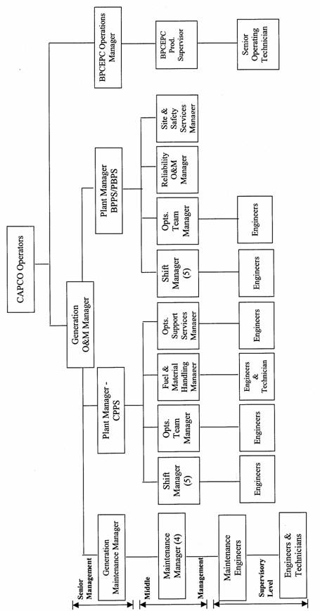
work and confined space activities; and auditing. 7.3 Site Organisation and Manning Levels
The management structure and levels in BPPS, CPPS and
BPCEPC is shown in fig. 7.3.1
Responsibilities
of Key Operating Positions
CAPCO
and its Operators recognise the benefit and importance of a broad range of
qualifications for key operational positions. These include a mix of experience,
maturity and corporate and professional qualifications. In addition CAPCO and
its Operators appreciate that technical competence and expertise further
enhances the quality of its key operational positions.
CLP
Power engaged several experienced practitioners in the natural gas operating
field during the initial natural gas operations stage between 1995 and 1998.
Most of the natural gas operation policy and procedures were developed during
this period. After CLP Power had gained sufficient experience and knowledge to
continue to operate safely and effectively, Gas Engineering Team (later called
Fuel Technology Team) with members from internal natural gas experts were
formed to continue to enforce the safe operations of natural gas facilities.
The
acceptable mix of qualifications will depend on the job classification and
reflects the level of responsibility and accountability. Examples of
established standards include:
Senior
Management must have at least 10 years
experience in appropriate, managerial and/or engineering posts in a relevant
industry with minimum qualification of a recognised college/university degree,
or membership/registration in a recognised professional body or extensive
relevant experience.
Senior
Management are responsible for setting policy and goals and ensuring safe,
effective and efficient operation and maintenance of the facility and
personnel.
Middle
Management must have at least 5 years
working experience in appropriate managerial and/or engineering posts in a
relevant industry with similar qualifications to senior management. The
incumbents in these positions possess expertise and experience to effectively support Senior Management in the
operation and maintenance of the facility.
Middle
Management is directly accountable to Senior Management and responsible for
operations in a designated facility or area. They provide direction to
subordinates to accomplish all necessary task within the limits of policy,
procedures and engineering and safety standards.
Supervisory
Level personnel are responsible for
execution of tasks under the direction of their supervision/management. The
qualifications for the third and fourth level positions (together forming the
Supervisory Level) vary according to the nature of the position. The positions
may include engineer, technician and foreman. A recognised college/university
qualification, or membership/registration in a recognised professional body or
appropriate relevant experience is required
for the engineer and technical level positions.
7.5 Safety Management Practices
7.5.1 Occupational Safety &
Health Management System
The objective of the Occupational Safety
& Health Management System (OSHMS) is to support GBG’s goal of providing an
injury free and healthy working environment, through the application of a
structured approach for safety and health management that complies with
external and internal safety and health requirements and conforms to CLP Power
Safety, Health, Environment and Quality Policy Statement.
In line with this objective, the
OSHMS is to provide a comprehensive management framework for establishing
appropriate safety and health standards, programs and training for
implementation in GBG for the purpose of:
·
Achieving objective/goal of the CLP
Power Safety, Health, Environment and Quality (SHEQ) Policy Statement and CLP
Power SHEQ Policy on Contractors & Supplier
·
Achieving full compliance with
statutory and company’s safety and health requirements
·
Identifying the safety and health
issues of GBG facilities, activities, products and services
·
Establishing short and long-term
safety and health objectives and targets
·
Developing Safety, Health and
Environment Plan and safety management plans and programs to meet objectives
and targets
·
Establishing responsibilities and
provide resources for the implementation, maintenance and improvement of this
OSHMS, to ensure proper management of GBG’s safety and health issues
·
Verifying compliance with regulatory
requirements and company policy, evaluate safety and health performance against
GBG’s objectives and targets, and communicate outcome of the evaluation
·
Minimizing risk and preventing
losses due to occupational safety and health incident
·
Ensuring systems are in place for
the anticipation, identification, evaluation, monitoring, control and
management of occupational hygiene stresses.
·
Enhancing the safety and health
standards of all GBG operations through continuous improvements.
CLP Power Operations Integrity Management System
CLP Power operates within a well
established Operation Integrity Management System (OIMS) which is adopted for
both Black Point and Castle Peak Power Station.
OIMS is adopted as a management framework
specifically to assist the accomplishment of safety, health and environmental
objectives. It is to be applied to all systems for managing process, plant,
equipment and activities within GBG. It builds upon and will enhance existing
programs to ensure operations integrity.
GBG will commit to implement OIMS in all
operational activities with the management leadership and commitment as
required under OIMS Element 1 - which requires that management establishes
policy, provides the perspective, establishes the framework, sets the
expectations, and provides the resources for successful operations.
There are
eleven principle elements to OIMS which are used as a reference to ensure that
systems and procedures are achieving expectations. The elements include
management, risk, facilities, documentation, personnel, operation &
maintenance, change, third party, incident, emergency, assessment. An
additional “OIMS element 12 – Asset management” and the corresponding
management principles have been drafted, which imposes the essential
requirements for effective management of GBG assets.
BPCEPC Health, Safety and
Environmental Procedure
BPCEPC have
developed a Health, Safety and Environmental Procedure which are consistent
practice by all their employees. The Health, Safety and Environmental Procedure
includes the safety practise of offshore platform, Nanshan Shore Base, offshore
gas pipeline, gas receiving station and also the main office building in
Shekou.
The goals for
BPCEPC are simply stated – no accidents, no harm to people and no damage to
environment. BPCEPC will continue to drive down the environmental and health
impact of their operations by reducing waste, emissions and discharges, and
using energy efficiently. BPCEPC will produce quality products that can be used
safely by their customers.
7.5.2 S/afety
assessment for new projects
Under
the Operational Integrity Management System, CLP Power begins evaluating the
potential risk at the conceptual stage of the project, and continues to do so
throughout the life of the plant. This is done to help reduce risk to a minimum
whilst still satisfying the commercial needs. The techniques used include
preliminary hazard assessment , Quantitative risk assessment (QRA) for
potentially hazardous installations,
area classification and Hazard and Operability (HAZOP) studies.
CLP
Power has a commitment to minimise the quantity of hazardous materials on any
new sites. This is an important part of the safety assessment of new projects
and expansions to existing projects.
BPCEPC
has utilised both qualitative and quantitative process hazards analysis for the
purpose of risk identification and analysis. Multiple Failure Effects Analysis
(MFEA), Fault Tree Analysis (FTA) and HAZOP were used at various design stages
of the project to ensure risks were minimised. BPCEPC has adopted the
operational rule of "three failures to safe" as a guiding principle
for its operations. In other words, for any particular process component or
system, three separate failures could occur and operational conditions would
remain safe. This principle ensures adequate redundancy and controls are
applied to process design and operations.
As
potential problems were realised during the process hazards analysis, a formal
system for communicating these potential problems was used. These potential
problem reports were reviewed by Engineering, Production, the Project
Management Team and Safety, Health and Environmental Personnel. Appropriate
solutions for correcting, addressing and/or managing these problem areas were
documented on the report and implemented in
the field.
In
addition to the process hazards analysis, an independent safety, health and
environmental protection audit was conducted during the final design. This
audit focused on compliance with design basis, regulatory compliance, cause and
effect charts, layout, operational controls, operational procedures and
practices. The audit findings were presented to BPCEPC Management and the
Project Management Team. A formal response to the audit findings, including an
itemised response and action plan for addressing each audit finding, was
presented to the audit team. The audit team periodically monitored responses,
as well as updates to ensure appropriate measures were taken during the course of construction, installation, commissioning
and start-up.
7.5.3 Inspection and maintenance
Black Point and
Penny’s Bay Power Station (BPPS/PBPS), Castle Peak Power Station (CPPS)and
Generation Maintenance Department (GMD) have developed schedule, routine
procedures and instructions for regular inspection and maintenance of the gas
system. These included the liaison with other departments, third parties and
those responsible for gas transmission process and control, i.e. System
Operation of CLP Power and Gas Receiving Station of BPCEPC. Fuel Technology /
TSD is normally the representative from CLP Power responsible to liaison with
BPCEPC on maintenance activities.
In
view of this organisation structure and limited manpower of the Station, a
Computerised Maintenance Management System (CMMS) provides the station staff at
all levels with adequate information for the management of operation and
maintenance of the station assets and plant
equipment and maintenance process installed.
This
CMMS provides sufficient information for the Station Management to exercise
Management Control and for Maintenance Engineers to make Engineering Decision.
It also smoothes work order flow, inventory control and cost analysis.
Maximo Series 5 is selected as the basic
modules for CMMS in BPPS. Maximo system is made up of 12 interconnected modules
tied to an Oracle database on a HP UNIX server.
BPCEPC
utilises a computer based preventive maintenance system, MAXIMO, for generating
work orders for inspection and maintenance of equipment, controls and systems
at each operating location. Inspection and maintenance frequencies are
established in the system based on regulatory requirements or internationally
accepted maintenance standards, such as outlined by the American Petroleum
Institute. In addition to generating work orders, each inspection and/or
maintenance performed is documented into the system, providing a documented
performance and maintenance history on each piece of equipment or system on
site.
Performance
and Regulatory Compliance, as pertaining to the preventive maintenance
conducted on site, are monitored and evaluated on a quarterly basis during the
safety, health and environmental audits conducted at each operating location.
Any deficiencies are noted in the audit report and must be addressed by
facility supervision.
7.5.4 Procedures for altering design/equipment
Management of Change
The Management of Change
System (MOC) applies to any addition, revision, deletion, modification, or
replacement (except replacement in kind) that has impact on safety, health
& environment, regulatory compliance and plant integrity & reliability.
The
Objectives of the System are to ensure:
·
Changes are
identified
·
Changes are
evaluated and control measures are in place to address SHE risks introduced,
impact on regulatory compliance or relate to plant integrity & reliability
that would lead to major loss in operation
·
SHE Risks
associated with the change are assessed and managed as appropriate
·
Changes are
documented and communicated to affected parties
·
Training on the
change if required
·
Evaluation is
performed on the outcome / result of the change in meeting the original intent
/ purpose
·
Temporary
changes and their need, scope, time frame and control measures are reviewed
regularly
BPCEPC follows its Management of Change
procedure as outlined in the BP HSE manual. All temporary and permanent changes
to organization, personnel, systems, procedures, equipment, products, materials
or substances will be evaluated and managed to ensure that health, safety and
environmental risks arising from these changes remain at an acceptable level.
7.5.5 Procedures for updating procedures
All
CLP Power procedures are being incorporated into the OIMS system which ensures
all documents are numbered and have a revision date on. The controlled copies
are the most up to date version, and any changes to the procedures have to be
approved by the responsible manager for the
particular group of procedures.
As
noted in Section 7.5.4, BPCEPC utilises the Management of Change Standard
outlined in its Safety and Health Manual as a means for reviewing any operating
procedural changes, particularly those which affect design, safety or control
system intent. The same procedures would apply as noted previously. As
required, HAZOP analysis are conducted for procedural changes. BPCEPC’s
practice concerning Operating, Emergency, Safety, Health and Environmental
Procedures is to review each procedure periodically (at least annually) to
ensure they reflect actual operations, comply with regulatory requirements and
incorporate regulatory requirements. Any changes to these procedures are
communicated to all personnel.
7.5.6 Permit-to-work system
The
Power System Safety Rules states that no repairs, maintenance, cleaning or
alternation can be carried out on any system in the power station without a
valid safety document in force except those specified in the Safety Rules such
as floating of safety valves and hydraulic test. The safety document required
may be a Permit-to-Work, Permit-to-Work with restoration of Motive Power,
Limited Work Certificate or Sanction For Test depending on the nature of the
work to be undertaken, and these safety documents will only be issued in strict
accordance with the current Power System Safety Rules.
For
BPCEPC, before conducting work that involves confined space entry, work on
energy systems, ground disturbance in locations where buried hazards may exist,
or hot work in potentially explosive environments, a permit must be obtained
that :
·
Defines scope of work
·
Identifies hazards and
assesses risk establishes control measures to eliminate or mitigrate hazards
·
Links the work to other
associated work permits or simultaneous operations
·
Is authorized by the
responsible person
·
Communicates above
information to all involved in the work
·
Ensures adequate control
over the return to normal operations
7.5.7 Arrangements with contractors on safety matters
A
contractor management system was set up to provide an incident-free working
environment by establishing a safety awareness culture through effective and
efficient third party service management practices, this includes:
·
Ensure
contractors perform in a manner consistent and compatible with the GBG's
policies and business objectives, CLP corporate SHE policy, as well as in compliance
with the legislation.
·
Provide for the
evaluation and selection of suppliers capable of performing work in a safe and
environmentally sound manner.
·
Provide guidance
on Company requirements for effective third party services management.
·
Provide regular
feedback on supplier performance to encourage continual improvement in the
service provided, and ensure that deficiencies are corrected.
The partnership
approach with contractors has already yielded good results on SHE performance
of contractors. The approach is to be further cultivated so that we could work
closely with contractors’ SHE personnel to enhance and motivate them to deliver
the expected roles and results. Also, CLP Power needs to review the
effectiveness of the regular SHE induction course and the monthly contractor
briefing to further improve their effectiveness and quality to ensure these are
organized and delivered in a quality and efficient manner.
BPCEPC provides its own induction
course and appropriate orientation for its employees and contractors applicable
to the inherent hazards of a gas production facility. Requirements have been
developed for contractors and their subcontractors performing work on BP
facilities/work site and exclusively for BP at contractor work sites. Contractors
will ensure that any subcontractor whom they employ meets these same
requirements. Contractors will take any additional precautions necessary to
prevent harm to personnel or damage to property and the environment.
7.5.8 Personnel protection
1.
Inside Natural gas control areas
·
Smoking is totally forbidden.
·
Use of naked light is not allowed.
Where there is no alternative to using naked lights such as in the event of
welding, then a Hot Work Permit is required.
·
Use sparkproof hand tools wherever practicable
and only intrinsically safe equipment. The use
of portable electric equipment and tools which are capable of causing ignition
are forbidden unless covered by a safety document.
·
Always monitor the atmosphere before
commencing work and during work.
·
Always carry a personal gas monitor
to protect people.
2.
General
·
Protective clothing, shoes, gloves
etc should be worn as instructed.
·
Special safety equipment such as
breathing apparatus, fire retardant clothing etc should be made readily
available and used as directed.
·
Fire extinguishers should be placed
readily available where work is being carried out.
·
Always follow the safety procedures
related to natural gas.
·
Use only approved gas monitoring
equipment.
7.5.9 Reporting and investigation of incidents
The Incident Investigation and Management
System covers all safety, health and environmental reportable
incidents/Near-misses which involve direct employees, contractors, property,
location or activities hired, owned, controlled or supervised by Generation
Business Group.
The
System is specifically designed to report, investigate, and analyze on
incidents associated with the following:
·
Fatal accidents
·
Serious injury
& lost-time accidents
·
Electrical
accidents
·
Employee or
contractor occupational injury or illness
·
Plant incidents
·
All significant
and/or high potential property damage
·
Fire
accidents
·
raffic
accidents
·
Environmental
incidents
·
Near-miss cases
·
Emergency
response situations
·
Any events
reportable to regulatory agencies according to the Dangerous Occurrence
Regulation
The
degree of investigation should be linked to the actual and potential severity
of the incident.
For BPCEPC, incidents will be reported, investigated and analysed to
prevent recurrence and improve our performance. The investigations will focus
on root causes and /or system failures. Corrective actions and preventive
measures will be utilized to reduce future injuries and losses.
7.6 Site
Safety Committee
7.6.1 CAPCO Safety, Occupational Health and Environment
Committee (SOHEC)
·
Being the highest management
committee for approval and endorsement of any SHE initiatives and set
management goal and expectation of SHE matters in GBG
·
Approve the annual CAPCO SHE plan
·
Set high level direction and
objectives for managing SHE matters in GBG
·
Monitor the program progress and
review performance
7.6.2 GBG OIMS
Steering Committee
·
Endorse the annual CAPCO SHE Plan
·
Approve objectives for safety and
health performance in consistent with overall policies and objectives
·
Monitor performance and regulatory
compliance through
on-going review of major
incidents and performances
periodic review of training and
operating practices
review of OIMS and other
compliance assessments audits
committee inspections of
facilities and operation
7.6.3 SHE Committee at each Operation Unit
·
Review SHE performance of the
operation unit
·
Monitor the progress and status of
the implementation of safety and health initiatives
·
Feedback and communicate the safety
and health programs
7.6.4 BPCEPC Safety Committee
During
normal operations, the Gas Receiving Station does not have an ample number of
personnel to support a site safety committee. However, site safety, health and
environmental issues are discussed in weekly safety meetings. These issues are
forwarded to the Production Manager and the Safety, Health and Environmental Protection Manager in Shekou for handling, as
appropriate.
In
addition, BPCEPC has established a Safety, Health and Environmental Council in
Shekou, PRC, which includes Executive Management as Members. The Safety, Health
and Environmental Protection Manager co-ordinates quarterly Council Meetings to
discuss all safety, health and environmental protection issues, such as those
addressed in the weekly safety meetings. The Production Managers, Drilling
Manager, Materials Manager, Project Team Management and Human Resources Management
are included in the quarterly meetings as sub-committee chairpersons, reporting
and discussing relevant safety, health and environmental performance and
relevant issues. Council Meeting Minutes are distributed to all participating
member and sub-committee chairpersons to use as a communication tool to
subordinate personnel within the organisation.
7.7 Review
of Human Tasks and Possible Errors
CLP Power
addresses the review of human tasks and possible errors in a number of ways and
at each stage in the development of a project.
At the design
stage, risk assessment and risk analysis are performed and areas of potential
problem are identified and the problem eliminated or mitigated. Human Factor
consideration is accessed during the HAZOP process of the system.
Moreover, there
are operating and maintenance instructions for all tasks that will be performed
on the stations. All the GBG staff will follow the instructions to carry out
the works. Job safety analysis also carry out to reduce the risk.
For BPCEPC, the
potential for human tasks or human errors are reviewed as a part of the Process
Hazards Analysis. Any potential risk or errors are minimised or eliminated
during the design and construction phase. During operation, the GRS supervisor
is designated the responsibility for reviewing the performance of tasks by both
BPCEPC personnel and its contractors for potential task of human errors.
7.8 Staff
Recruitment and Training
CAPCO
and its Operators recognise that personnel, whose work could affect the safety
of the facilities, equipment and operations, must have and maintain the
necessary knowledge and skills to execute their functions safely. Employees
receive adequate training prior to being assigned to positions involved in the
gas systems. The Operators also ensure that each employee receives the
appropriate refresher training necessary to maintain
the required knowledge and skill levels.
Key
managerial, professional and technical operational positions receive specific
training related to the safe performance of their jobs either locally or
internationally. This training include safe facility design and layout; safe
work, operational and maintenance practices; emergency response; hazards
identification, control and management; incident investigation and mitigation
techniques; and safety auditing techniques, as applicable.
Operators,
technicians, foremen and tradesmen have structured on-the-job and classroom
training programs regarding safe operations and maintenance practices for gas systems.
These training programs are arranged internally or with a recognised institution.
Appropriate measures are in place to ensure training and
appropriate authorisation of the various levels of personnel required to work
on the gas system. Contractor's personnel training will be evaluated prior to
work commencement and monitored during the
duration of the contract.Training records are maintained and monitored
for all employees of the Operators.
7.8.1 Training
Plan
The training plan highlights key training areas identified as essential
to ensure management and operational staff are fully trained to meet the
demands of using natural gas as a fuel for power generation. The training of
all staff is documented and recorded.
Topics on Authorisation Training
3.
Same for Competent Person –
Natural Gas & Senior Authorised Person – Natural Gas
Part 1 Natural Gas Safety
Practices
·
Natural Gas Production &
Transmission
·
Natural Gas Properties & Hazards
·
Properties & Hazards of Other
Flammable Gases
·
Natural Gas Safety Policy
·
Natural Gas Safe Working Practices
·
Gas Leak Detection & Gas Test
·
Emergency Response in Gas Incidents
Part 2 Protection of
Electrical Equipment in Hazardous Areas
·
Flammable Gases and Vapours
·
Area Classification
·
Ignition Sources
·
Principles of Ex Protection
·
Apparatus Group
·
Temperature Class
·
Ingress Protection
·
Flameproof Concept Exd
·
Increased Safety Concept Exe
·
Intrinsic Safety Concept Exi
·
Purged and Pressurised Concept Exp
·
Non Incentive
Concept ExN
·
Combined and other Concepts
·
Standards
·
Marking
For Senior Authorised Person –
Natural Gas
Part 3 SAP_NG
Authorisation
·
Safety on Handling & Operating
of Natural Gas
·
Analysing for Gas Work Hazards
·
Fighting Gas Incidents
·
Safety Procedures
For
BPCEPC, the students are given practical experience training at other BPCEPC
Operating locations, at Equipment Manufacturer's facilities or within BPCEPC
operations within
BPCEPC’s
ex-patriate employee staff are selected from various BP operations worldwide.
The selection process is based on applicable experience and education, past
performance and suitability to the working environment in China/Hong Kong.
BPCEPC's expatriate contractors are selected based on the same criteria as
BPCEPC's ex-patriate employee staff. All ex-patriate staff are required to
attend all required training under PRC and Hong Kong SAR regulations and ensure
that training is current.
7.9 Internal
Audit of Company Safety Management System
CLP
Power operates the OIM system which has an internal audit plan and each section
is audited at some point during a year. In addition, the companies Safety
Management Systems are audited on annual basis.
Operation review:
The
monitoring of compliance with operating procedures is conducted on a continuous
and programmed audit/review basis.
All
operations within CLP Power are under close supervision by qualified and
trained shift managers on a continuous 24 hour basis. The supervision is also
extended to cover front line maintenance and trouble shooting carried out by
the shift maintenance personnel and contractors.
BPCEPC
also provide continuous manning of gas receiving facilities
The
Operators have procedures for control of operational systems to ensure safe
operation, work permit procedures are in place and utilised at all the
Operators' facilities.
Adherence
to operational procedures is facilitated by periodic audits, manual and
computerised logs, operational records, data sheets, trend charts and routine
maintenance and testing.
Operations integrity assessment:
CAPCO
and its Operators have adopted a process that measures performance relative to
expectations which is essential to improve the operation and maintain
accountability. A system has been established as an approach for measuring how
well operations are meeting goals and objectives.
As
noted in previous sections, BPCEPC has established a comprehensive safety,
health and environmental protection auditing program for all its operating
facilities. BPCEPC has commenced to conduct comprehensive safety, health and
environmental audits of all its operating facilities and will continue each
year. The objectives of this comprehensive internal audit effort are to: verify
the compliance status of the facility with applicable regulations; verify the
compliance status of the facility with respect to BPCEPC policies and design
basis; confirm that applicable safety, health and environmental management
controls are in place and functioning properly; and access current practices to
identify areas or situations requiring corrective measures.