The construction, operation, restoration and aftercare
of the Extension have the potential to cause adverse water quality impacts if
not properly managed. This section
examines the potential impacts on the nearby water resources due to discharge
of construction runoff into the watercourses and marine waters, the potential
discharge of leachate into the surface and groundwater systems. The impacts are evaluated through a
review of the surface water and leachate management systems for the Extension.
The regulatory requirements and standards to protect
water quality are as follows:
·
Water Pollution Control Ordinance (WPCO) (Cap. 358);
· Environmental Impact Assessment Ordinance (Cap. 499.
S.16), Technical Memorandum on Environmental Impact Assessment Process
(EIAO-TM), Annexes 6 and 14;
·
Technical Memorandum Standards for Effluents
Discharged into Drainage and Sewerage Systems, Inland and Inshore Waters (TM);
· Practice Note for
Professional Persons on Construction Site Drainage (Prop PECC PN 1/94); and,
·
6.2.1
Water Pollution Control Ordinance (WPCO)
The WPCO is the legislation for the control of
water pollution and water quality in
The assessment area (thereafter referred to as the
Study Area) is defined in the EIA Study
Brief (No. ESB-119/2004) as all areas within 500m from
the boundary of the Extension Site (see Figure 6.2a). In accordance with the WPCO, the Study Area is located inside
the Junk Bay WCZ and is in close proximity to the Eastern Buffer WCZ.
The WQOs for the Junk Bay WCZ and Eastern Buffer WCZ,
which are presented in Tables 6.2a and 6.2b, respectively, are applicable as
evaluation criteria for assessing compliance of any effects from the discharges
of the Project.
Table 6.2a Water
Quality Objectives for Junk Bay Water Control Zone
|
Water Quality
Objectives |
Junk Bay WCZ |
|
A. AESTHETIC
APPEARANCE |
|
|
(a) Waste
discharges shall cause no objectionable odours or discolouration of the
water. |
Whole Zone |
|
(b) Tarry
residues, floating wood, articles made of glass, plastic, rubber or of any
other substance should be absent. |
Whole Zone |
|
(c) Mineral
oil should not be visible on the surface. Surfactants should not give rise to
a lasting foam. |
Whole Zone |
|
(d) There
should be no recognisable sewage-derived debris. |
Whole Zone |
|
(e) Floating, submerged and
semi-submerged objects of a size likely to interfere with the free movement
of vessels, or cause damage to vessels, should be absent. |
Whole Zone |
|
(f) Waste
discharges shall not cause the water to Whole Zone contain substances which
settle to form objectionable deposits. |
Whole Zone |
|
B. BACTERIA |
|
|
(a) The level
of Escherichia coli should not exceed 610 per 100 mL, calculated as the
geometric mean of all samples collected in one calendar year. |
|
|
(b) (Repealed
L.N. 451 of 1991) |
- |
|
(c) The
level of Escherichia coli should not exceed 1000 per 100 ml, calculated as
the running median of the most recent 5 consecutive samples taken at
intervals of between 7 and 21 days. |
Inland waters |
|
C. COLOUR |
|
|
Waste discharges
shall not cause the colour of water to exceed 50 Hazen units. |
Inland waters |
|
D. DISSOLVED
OXYGEN |
|
|
(a) Waste
discharges shall not cause the level of dissolved oxygen to fall below 4 mg L-1 for 90% of the sampling occasions during the year;
values should be calculated as the water column average (arithmetic mean of
at least 3 measurements at 1 m below surface, mid-depth and 1 m above
seabed). In addition, the concentration of dissolved oxygen should not be
less than 2 mg L-1 within 2 m of the seabed for 90% of the
sampling occasions during the year. |
Marine waters excepting Fish Culture Subzones |
|
(b) The
dissolved oxygen level should not be less than 5 mg L-1 for 90% of the sampling occasions during the year;
values should be calculated as water column average (arithmetic mean of at
least 3 measurements at 1 m below surface, mid-depth and 1 m above seabed).
In addition, the concentration of dissolved oxygen should not be less than 2
mg L-1 within 2 m of the seabed for 90%
of the sampling occasions during the year. |
Fish Culture Subzones |
|
(c) Waste
discharges shall not cause the level of dissolved oxygen to be less than 4 mg
L-1. |
Inland waters |
|
E. pH |
|
|
(a) The pH of the water should
be within the range of 6.5-8.5 units. In addition, waste discharges shall not
cause the natural pH range to be extended by more than 0.2 units. |
Marine waters (L.N. 451 of 1991) |
|
(b) (Repealed L.N. 451 of 1991) |
- |
|
(c) The pH of the water
should be within the range of 6.0-9.0 units. |
Inland waters |
|
F. TEMPERATURE |
|
|
Waste discharges
shall not cause the natural daily temperature range to change by more than
2.0oC. |
Whole Zone |
|
G. SALINITY |
|
|
Waste discharges shall not cause the natural
ambient salinity level to change by more than 10%. |
Whole Zone |
|
H. SUSPENDED SOLIDS |
|
|
(a) Waste discharges shall
neither cause the natural ambient level to be raised by 30% nor give rise to
accumulation of suspended solids which may adversely affect aquatic
communities. |
Marine waters |
|
(b) Waste discharges shall not
cause the annual median of suspended solids to exceed 25 mg L-1. |
Inland waters |
|
I. AMMONIA |
|
|
The ammonia nitrogen level should not be more
than 0.021 mg L-1, calculated as the annual average (arithmetic
mean), as unionized form. |
Whole Zone |
|
J. NUTRIENTS |
|
|
(a) Nutrients shall not be
present in quantities sufficient to cause excessive or nuisance growth of
algae or other aquatic plants. |
Marine waters |
|
(b) Without limiting the
generality of objective (a) above, the level of inorganic nitrogen should not
exceed 0.3 mg L-1, expressed as annual water column average
(arithmetic mean of at least 3 measurements at 1 m below surface, mid-depth
and 1 m above seabed). |
Marine waters |
|
K. 5-DAY BIOCHEMICAL
OXYGEN DEMAND |
|
|
Waste discharges shall not cause the 5-day biochemical oxygen demand
to exceed 5 mg L-1. |
Inland waters |
|
L. CHEMICAL OXYGEN DEMAND |
|
|
Waste discharges shall not cause the chemical oxygen demand to exceed
30 mg L-1. |
Inland waters |
|
M. DANGEROUS SUBSTANCES |
|
|
(a) Waste discharges shall
not cause the concentrations of dangerous substances in the water to attain
such levels as to produce significant toxic effects in humans, fish or any
other aquatic organisms, with due regard to biologically cumulative effects
in food chains and to toxicant interactions with each other. |
Whole Zone |
|
(b) Waste discharges of
dangerous substances shall not put a risk to any beneficial uses of the
aquatic environment. |
Whole Zone |
|
N-O (Repealed L.N. 451 of 1991) |
Whole Zone |
Table 6.2b Water
Quality Objectives for Eastern Buffer Water Control Zone
|
Water Quality
Objectives |
Eastern Buffer WCZ |
|
A. AESTHETIC
APPEARANCE |
|
|
(a) There should
be no objectionable odours or discolouration of the water. |
Whole Zone |
|
(b) Tarry
residues, floating wood, articles made of glass, plastic, rubber or of any
other substances should be absent. |
Whole Zone |
|
(c) Mineral
oil should not be visible on the surface. Surfactants should not give rise to
a lasting foam. |
Whole Zone |
|
(d) There
should be no recognisable sewage-derived debris. |
Whole Zone |
|
(e) Floating, submerged and
semi-submerged objects of a size likely to interfere with the free movement
of vessels, or cause damage to vessels, should be absent. |
Whole Zone |
|
(f) The
water should not contain substances which settle to form objectionable
deposits. |
Whole Zone |
|
B. BACTERIA |
|
|
(a) The level
of Escherichia coli should not exceed 610 per 100 mL, calculated as the
geometric mean of all samples collected in a calendar year. |
Fish Culture Subzones |
|
(b) The level
of Escherichia coli should be less than 1 per 100 mL, calculated as the
geometric mean of the most recent 5 consecutive samples taken at intervals of
between 7 and 21 days. |
Water Gathering Ground Subzones |
|
(c) The
level of Escherichia coli should not exceed 1000 per 100 mL, calculated as
the geometric mean of the most recent 5 consecutive samples taken at
intervals of between 7 and 21 days. |
Other inland waters |
|
C. COLOUR |
|
|
(a) Human activity should
not cause the colour of water to exceed 30 Hazen units. |
Water Gathering Ground Subzones |
|
(b) Human activity should
not cause the colour of water to exceed 50 Hazen units. |
Other inland waters |
|
D. DISSOLVED OXYGEN |
|
|
(a) The level
of dissolved oxygen should not fall below 4 mg L-1 for
90% of the sampling occasions during the whole year; values should be
calculated as water column average (arithmetic mean of at least 3
measurements at 1 m below surface, mid-depth and 1 m above seabed). In
addition, the concentration of dissolved oxygen should not be less than 2 mg
L-1 within 2 m of the seabed for 90% of the sampling
occasions during the whole year. |
Marine waters excepting Fish Culture Subzones |
|
(b) The level of dissolved oxygen should not be less
than 5 mg L-1 for 90% of the sampling occasions
during the year; values should be calculated as water column average
(arithmetic mean of at least 3 measurements at 1 m below surface, mid-depth
and 1 m above seabed). In addition, the concentration of dissolved oxygen
should not be less than 2 mg L-1 within 2 m
of the seabed for 90% of the sampling occasions during the whole year. |
Fish Culture Subzones |
|
(c) The
level of dissolved oxygen should not be less than 4 mg L-1. |
|
|
E. pH |
|
|
(a) The pH of the water should
be within the range of 6.5-8.5 units. In addition, human activity should not
cause the natural pH range to be extended by more than 0.2 units. |
Marine waters |
|
(b) Human activity should not
cause the pH of the water to exceed the range of 6.5-8.5 units. |
Water Gathering Ground Subzones |
|
(c) Human activity should
not cause the pH of the water to exceed the range of 6.0-9.0 units. |
Other inland waters |
|
F. TEMPERATURE |
|
|
Human activity
should not cause the natural daily temperature range to change by more than
2.0oC. |
Whole Zone |
|
G. SALINITY |
|
|
Human activity should not cause the natural
ambient salinity level to change by more than 10%. |
Whole Zone |
|
H. SUSPENDED SOLIDS |
|
|
(a) Human activity should
neither cause the natural ambient level to be raise by more than 30 % nor
give rise to accumulation of suspended solids which may adversely affect
aquatic communities. |
Marine waters |
|
(b) Human activity should not
cause the annual median of suspended solids to exceed 20 mg L-1. |
Water Gathering Ground Subzones |
|
(c) Human activity should not cause the
annual median of suspended solids to exceed 25 mg L-1. |
Other inland waters |
|
I. AMMONIA |
|
|
The un-ionized ammoniacal nitrogen level
should not be more than 0.021 mg L-1, calculated as the annual
average (arithmetic mean). |
Whole Zone |
|
J. NUTRIENTS |
|
|
(a) Nutrients should not be present in quantities
sufficient to cause excessive or nuisance growth of algae or other aquatic
plants. |
Marine waters |
|
(b) Without limiting the generality of
objective (a) above, the level of inorganic nitrogen should not exceed 0.4 mg L-1, expressed as annual water column average
(arithmetic mean of at least 3 measurements at 1 m below surface, mid-depth
and 1 m above seabed). |
Marine waters |
|
K. 5-DAY BIOCHEMICAL
OXYGEN DEMAND |
|
|
(a) The 5-day biochemical oxygen demand
should not exceed 3 mg L-1. |
Water Gathering Ground Subzones |
|
(b) The 5-day biochemical oxygen demand
should not exceed 5 mg L-1. |
Other inland waters |
|
L. CHEMICAL OXYGEN DEMAND |
|
|
(a) The chemical oxygen demand should not
exceed 15 mg L-1. |
Water Gathering Ground Subzones |
|
(b) The chemical oxygen demand should not
exceed 30 mg per litre. |
Other inland waters |
|
M. TOXIC SUBSTANCES |
|
|
(a) Toxic substances in
the water should not attain such levels as to produce significant toxic,
carcinogenic, mutagenic or teratogenic effects in humans, fish or any other
aquatic organisms with due regard to biologically cumulative effects in food
chains and to interactions of toxic substances with each other. |
Whole Zone |
|
(b) Human activity should not
cause a risk to any beneficial use of the aquatic environment. |
Whole Zone |
6.2.2
Technical Memorandum for Effluent
Discharges into Drainage and Sewerage Systems, Inland and Inshore Waters (TM)
All discharges from the Project are required to comply
with the Technical Memorandum for Effluents Discharged into Drainage and
Sewerage Systems, Inland and Inshore Waters (TM) issued under Section 21 of
the WPCO. The TM defines discharge limits for different types of receiving
waters. Under the TM, effluents discharged into the
drainage and sewerage systems, inshore and inshore waters of the WCZs are
subject to pollutant concentration standards for particular discharge
volumes. Any new discharges within
a WCZ are subject to licence conditions and the TM acts as a guideline for setting discharge standards for
inclusion in the licence. Any
sewage from the proposed construction and operational activities should comply
with the standards for effluent discharged into the foul sewers, inshore waters
or marine waters of the
Currently, the treated effluent from the existing
leachate treatment plant of the existing SENT Landfill (thereafter referred to
as the Bioplant) is discharged to the Tseung Kwan O Sewage Treatment Works (TKO
STW). The quantity and composition
of any effluent discharged from the landfill shall not exceed any of the
regulatory limits as stipulated in the existing discharge license.
6.2.3
Environmental Impact
Assessment Ordinance (Cap. 499. S.16), Technical
Memorandum on Environmental Impact Assessment Process (EIAO-TM)
Annexes 6 and 14 of
the Environmental Impact Assessment Ordinance
(Cap. 499. S.16), Technical Memorandum on Environmental Impact Assessment
Process (EIAO-TM) provide general guidelines and criteria to be used in
assessing water quality issues.
6.2.4
Practice Note for Professional Persons on
Construction Site Drainage (ProPECC PN 1/94)
The
ProPECC PN 1/94 issued by the EPD provides some basic environmental
guidelines for the handling and disposal of construction site discharges to
prevent or minimise construction impacts on water quality.
Whilst the technical
circulars are non-statutory, they are generally accepted as best guidelines in
6.2.5
Chapter 9 of the Hong Kong Planning Standards and Guidelines (HKPSG)
provides guidance for including environmental considerations in the planning of
both public and private developments.
It applies both to the planning of permanent or temporary uses which
will have potential to cause significant changes to the biophysical environment
or which are sensitive to environmental impacts. Section 5 in Chapter 9 of
the HKPSG provides additional information on regulatory guidelines
against water pollution for sensitive uses such as aquaculture and fisheries
zones, bathing waters and other contact recreational waters.
6.3
Assessment Methodology
The construction method and sequence described in Section
3 were reviewed to assess
the remoteness of the construction works from existing and committed Water
Sensitive Receivers (WSRs). The WSRs
were identified according to guidance provided in the EIAO-TM and HKPSG.
The design of the Extension, construction sequence,
duration and activities, and the operation, restoration and aftercare
activities were reviewed to identify activities with the potential to impact
upon identified WSRs and other water courses.
Following the identification of WSRs and potential
water quality impacts, the scale, extent and severity of potential net (ie
unmitigated) construction, operation/restoration and aftercare impacts were
evaluated, taking into account all potential cumulative effects including those
of adjacent projects, with reference to the WPCO criteria.
Where net water quality impacts exceed the appropriate
WPCO criteria, practical water pollution control measures/mitigation
proposals were identified to ensure compliance with reference to the WPCO criteria. Water quality monitoring and audit
requirements were developed, if necessary, to ensure the effectiveness of the
water pollution control and mitigation measures.
6.4
Water Quality
Sensitive Receivers and Baseline Conditions
6.4.1
Existing Conditions
The south-western part of the Extension Site will be
located on formed land at TKO Area 137 (see Figure 6.4a). It is currently occupied by a
temporary fill bank, where the stormwater drainage channels have been well
established. The potential water
quality impacts arising from decommissioning the fill bank has been assessed
under the EIA for the Fill Bank ([1])
which
concluded that no unacceptable residual water quality impacts were expected
during the decommissioning period.
The northern part of the Extension Site will be piggybacked
onto the southern slopes of the existing SENT Landfill and the infrastructure
area which includes the site office, the Bioplant and
the landfill gas treatment plant (see Figure 6.4a). These facilities will be demolished
after those for the Extension have been constructed and commissioned ([2]).
The eastern part of the Extension will occupy a small
part of the Clear Water Bay Country Park (CWBCP) (see Figure 6.4a).
Two seasonal streams, namely S1 and S2, were recorded
within the Study Area. As shown in Figure
6.4a, S1 and S2 are located at Ha Shan Tuk and Hin Ha Au
respectively. They are small in size, S1 and S2 are approximately 56 m and 98 m in length
respectively. Both of them are
classified as seasonal streams because they were found to have limited water
flows during the wet season and no water flows during the dry season. Photographic records of the streams are
illustrated in Figure 9.7d in Section 9 – Ecology Impact Assessment
and it is concluded in Section 9 that
the ecological significance of these two seasonal streams is considered to be
low.
6.4.2
Existing Landfill Liner System
The existing SENT Landfill
has been designed and constructed, as a secure containment facility
incorporating a leachate containment system and a leachate collection system
covering the entire waste boundary of the landfill. As the site is lined, leachate within
the landfill is collected and treated to ensure that there will be no off-site
migration of leachate from the landfill to the environment. The leachate containment and collection
system comprises, from the bottom to the top, a layer of geocomposite
groundwater drainage layer, a 1.5 mm of textured High Density Polyethylene
(HDPE) Secondary liner, a 6 mm of geocomposite clay liner (GCL), a 2 mm of
textured HDPE primary liner, a layer of non-woven geotextile cushion, a 200 mm
granular leachate drainage layer, and a layer of woven geotextile filter.
6.4.3
Existing Leachate/Wastewater Treatment
Facilities
At present, the
leachate/wastewater generated from the SENT Landfill is collected and delivered
to the Bioplant for treatment prior to discharge to a sewer connecting to the
TKO STW. Landfill leachate is the
predominant load whereas wastewater from the administrative office as well as
laboratory and maintenance building is also collected and treated at the
Bioplant. The Bioplant comprises an
equalization tank, a metals precipitation system, a leachate heater and heat
exchanger, an ammonia stripping system, a pH adjustment system, a sequencing
batch reactor (SBR) and sludge handling system. Wastewater is pumped into the Bioplant
and stored in the equalization tank.
The pH of the effluent from the equalization tank is elevated by adding
lime slurry in order to precipitate out heavy metals. After gravity clarification and
filtration, the wastewater is heated and sprayed through the ammonia
strippers. In the ammonia
strippers, hot air is blown through and it separates the ammonia from the
wastewater. The thermal catalytic
unit will completely oxidise the off-gas that contains ammonia. The pH of the wastewater is then
adjusted and consequently pumped to the SBR to remove the remaining organic
pollutants and ammonia. The treated
effluent is stored in an effluent holding tank and then discharged to the sewer
at a rate not exceeding 210 m3 hr-1.
6.4.4
Water Sensitive Receivers (WSRs)
In order to evaluate the water quality impacts
resulting from the construction and operation/restoration and aftercare of the
Extension, the WSRs have been identified in accordance with the EIAO-TM and HKPSG.
The WSRs in the Study Area are identified and
presented below:
· Inshore waters in
·
· Surface water
including two seasonal streams S1 and S2; and
· Groundwater.
6.4.5
Baseline Groundwater Conditions
Groundwater samples were
collected from the locations GW1, GW2, GW3, and GW4 of the SENT landfill as
shown in Figure 6.4a where GW1 and GW2
are up-gradient, and GW3 and GW4 are down-gradient. Water samples from each location were
collected once per week for a total of four consecutive weeks between June and
July 2007. The results of the
groundwater baseline monitoring are presented in Annex F.
By comparing the groundwater quality
of the up-gradient and the down-gradient monitoring wells,
it is evident that the groundwater quality of the down-gradient wells is
influenced by the influx of seawater.
6.5
Construction
Phase Impact Assessment
Potential sources of impacts to water quality from the
construction activities are:
· construction
runoff;
· wastewater
generated from construction activities; and
· sewage generated from
the workforce.
6.5.2
Construction Runoff
Construction runoff
from site areas may contain high loading of SS and contaminants. Potential water pollution sources from
construction site runoff include:
· runoff and erosion
from site surfaces, earth working areas and stockpiles;
· demolition of
existing infrastructure for the SENT Landfill; and
· tunnel excavation for
the twin drainage tunnel.
Construction
runoff may cause physical, biological and chemical effects. Its physical effect can cause blockage of
drainage channels due to the deposits of increasing SS from the site. Chemical and biological effects are
however highly dependent on its chemical and nutritional contents. Runoff containing significant amount of
concrete and cement-derived materials would lead to increasing turbidity and
discoloration, elevation in pH, and accretion of pH solids.
During the first
year of construction, works including site formation and construction of site
office buildings, workshops, landfill gas and leachate treatment plants will be
carried out. Excavation is
necessary for the construction of the new infrastructure. A perimeter cut-off channel will be
constructed around the Extension Site to divert water from outside the site
boundary before commencement of site formation works. In addition, intercepting channels will
be provided, for example along the edge of excavation to prevent stormwater
runoff from washing across exposed soil surfaces. The construction runoff will be
discharged off site after passing through a sedimentation tank or silt
traps. It is anticipated that, with the implementation of good
construction practice, as stated in ProPECC PN1/4, and appropriate
mitigation measures (see Section 6.8),
contamination of construction runoff will be minimal and there will be no
unacceptable water quality impacts to the receiving water bodies, ie surface
water including two seasonal streams S1 and S2, inshore waters in Junk Bay and
Joss House Bay, and Clear Water Bay Country Park.
Modification of the landfill
gas wells of the existing SENT Landfill is required for the accommodation of
the new basal liners of the Extension.
No leachate leak will occur as the works will be carried out above the
impermeable liner of the capping system.
In the second year, the demolition of the
existing infrastructure at the existing SENT Landfill will be carried out. There will be no wastewater
generated by the demolition of existing facilities. As a preventive measure, all sewers and drains will be sealed to
prevent building debris, soil and etc from entering public sewers/drains before
commencing any demolition works.
The fuel and waste lubricant oil from the
on-site maintenance of machinery and equipment will be collected by a licensed
chemical waste collector. The runoff
containing oil and grease will pass through the oil interceptor before being
discharged off-site.
6.5.3
Wastewater Generated from Construction
Activities
In order
to drain the surface water collected at the south-eastern corner of the
Extension to the side slope near TKO Area 137, a 2 m-diameter twin drainage
tunnel will be constructed near the side slope of the landfill, separated from
the side slope liner system of the Extension by a considerable thickness of in-situ rock (see Figure 3.3i). A micro-tunnel boring machine (TBM) will
be used for the main tunnel excavation.
There
will be no wastewater generated from tunnel excavation, except the recycle
water and bentonite slurry required for the cooling of the cutter head during
boring rocks and soil respectively.
The recycle water will be conveyed to the sedimentation tanks for
treatment and most of the treated water will be reused in the boring
operations. Similarly, the bentonite slurry will be recirculated, wherever
practicable, following settlement of cuttings. Only limited amount of excess
water will be disposed to the surface drains in TKO Area 137 after proper
treatment. The disposal of the
treated water in compliance with the discharge license granted at the later
stage will be required and hence no adverse impact to the nearby water bodies
is expected. Prior to tunnel
excavation, ground treatment works will be carried out and hence the tunnel excavation
is unlikely to cause any unacceptable variation of the groundwater table.
Used bentonite slurries will
be reconditioned and reused on-site as far as possible. The residual bentonite slurry will be
mixed with dry excavated material for disposal at the designated public filling
facilities. In accordance with ProPECC PN 1/94, if the used bentonite
slurry is intended to be disposed of through the public drainage system, it
should be treated to the respective effluent standards applicable to foul
sewers, storm drains or the receiving waters as set out in the TM under
the WPCO.
6.5.4
Sewage Generated from the Workforce
Sewage will arise from the sanitary
facilities provided for the on-site workforce. The characteristics of sewage would
include high levels of 5-day Biochemical Oxygen Demand (BOD5), ammonia
and E.coli counts. It is
estimated maximum of 170 workers will be working simultaneously at the
construction site during construction phase. Sufficient chemical toilets will be provided
for use by the workforce. In
addition, no sewage will be allowed to discharge directly into the surrounding
water body without treatment. With
this regard, adverse impacts to water quality as a result of handling and
disposal of sewage generated by the workforce are not expected.
6.6
Operation/ Restoration Phase Impact Assessment
6.6.1
Potential Impacts
During the operation/restoration phase of the
Extension, solid wastes deposited in the landfill will decompose by a
combination of chemical, physical and biological processes through which solid,
liquid and gaseous by-products are produced and all of them would be of concern
in the overall management of a landfill.
The liquid by-product is referred to as leachate and is the main concern
for the water quality impact of the Extension.
Figure 6.6a shows the
leachate generation processes.
There are two sources of water in the landfill, ie, the water present in
the waste when landfilled (primary leachate) and the water added to the
landfill from rainfall and groundwater inputs (secondary leachate). During rainy days, the primary leachate
is soon overshadowed by secondary leachate, which will control the long-term
leachate generation. Secondary
leachate arises from infiltration of rainwater through the active tipping face
and daily cover area. As the
landfill will be fully lined, no leachate will be generated from groundwater
infiltration.
Other potential impacts may include the wastewater
produced during the daily operation of the office buildings and associated
facilities.
To summarise, the potential sources of impacts to
water quality from the operation/restoration activities include:
· uncontrolled
discharge of leachate from the active tipping area into surface water;
· sub-surface off-site
migration of leachate into groundwater and marine water due to potential pin
holes and defected seams in the liner;
· discharge of
improper treated effluent leachate from the LTP; and
· wastewater generated from
workforce.
To evaluate the above potential impacts, it is
necessary to examine in considerable detail of the surface water, groundwater
and leachate management systems proposed for the Extension. This will also facilitate the design of
a monitoring programme which could determine the degree to which the Extension
and any associated containment system is functioning in accordance with design
objectives and in compliance with the legislative criteria/standards.
The potential impact to groundwater quality due to
leakage of leachate is discussed as a whole for operation/restoration, and
aftercare phases in Section 6.7.
6.6.2
Surface Water Management
As discussed in Section 6.6.1,
leachate generated from rainfall infiltration will control the long-term
leachate generation. Surface water
management, which relates to the infiltration of rainfall through the landfill
surface, is discussed in this section.
The overall design objectives for the
surface water management system are to:
·
avoid
any surface water runoff from outside the Extension (including runoff from the
natural slopes of CWBCP and from restored slopes of the existing SENT Landfill)
from entering the waste boundary;
·
ensure
all runoff from the Extension site drains to
·
ensure segregation between clean rainwater, and water which
has come into contact with waste and therefore will be treated as leachate.
The following
design features have been incorporated in the outline design of the surface
water management to minimise leachate generation and control the discharge of
leachate into surface water channels.
· Clean surface
water runoff will be separated from contact with waste by use of temporary
bunds, diversion channels and cut-off drains;
· Areas that have
been filled with waste, but not yet reached final grade, will be covered by
intermediate cover (with an impermeable liner) to minimise rainwater infiltration
into the waste and prevent erosion of the intermediate cover soil;
· The final cap (see
Figure
3.3c) will include the following main features or similar materials to
minimise rainwater infiltration into the waste:
(a)
A layer of CDV and topsoil mix - reduces infiltration
into the waste and wind erosion and provides temporary moisture retention;
(b)
A layer of compacted fill - minimise infiltration into
the waste through the cover;
(c)
A layer of geocomposite drainage layer - provides a
lateral path for water to exit rapidly;
(d)
A layer of HDPE liner - an impermeable membrane
effectively minimises infiltration into the waste and greatly reduces the
volume of leachate to be generated from restored areas and seeping of leachate
from waste slopes into surface water channels; and
(e)
A layer of non-woven geotextile - separates soil
grading layer from HDPE liner.
· Placement of the
final capping system will be implemented in phases throughout the life of the
Extension.
Detailed design of site drainage will be
based on the appropriate Hong Kong Government codes, including the DSD
Stormwater Drainage Manual (1994).
A Drainage Impact Assessment (DIA) has been carried
out for the Extension. The DIA has
concluded that the existing and planned surface water drainage infrastructure
in TKO Area 137 and the surrounding area is adequate to convey surface water
flows from the Extension and surrounding catchments to the existing and planned
discharge points. The estimated
daily flow rates under normal and extreme conditions at different operational
phases (refer to Section 3.6 for the
details of each phase) of the Extension are summarised in Table 6.6a.
Table 6.6a Predicted
Daily Flow Rates During Operational Phases
|
Phase |
Under |
Under Extreme Conditions |
|
|
m3 d-1 |
m3 d-1 |
|
1 |
732 |
1,058 |
|
2 |
1,354 |
1,952 |
|
3 |
1,602 |
2,306 |
|
4 |
1,893 |
2,722 |
|
5 |
2,108 |
3,027 |
|
6 |
2,366 |
3,390 |
Surface Runoff from
In order to avoid surface runoff from CWBCP from
entering the Extension Site, a permanent cut-off channel will be constructed
along the crest of the eastern side slope.
The southern part of this cut-off channel will drain by gravity to the
south-eastern corner of the Extension.
The northern part of this cut-off channel falls to the north, where it
will meet up with the cut-off channel for the existing SENT Landfill.
At present, the existing SENT Landfill
cut-off channel traverses the eastern edge of the landfill, and then turns to
the west, towards the existing SENT Landfill infrastructure area. As part of the Extension development,
this portion of the channel will be covered by waste and could not be used during
the operation/restoration phase of the Extension. A 2 m-diameter twin drainage tunnel will
be constructed near the side slope of the landfill, separated from the side
slope liner system of the Extension by a considerable thickness of in-situ rock (see Figure 3.3i). This twin tunnel will drain water
collected at the south-eastern corner of the Extension to the side slope near
TKO Area 137 where it joins the eastern boundary channel (see Figure
3.3i).
Run-off from Existing SENT Landfill
Runoff from the restored slopes of the existing SENT
Landfill will be uncontaminated but should be prevented from entering the
Extension Site. A perimeter cut-off
channel will be constructed around the Extension Site, and it will be connected
to the surface water drainage system to be incorporated into the existing SENT
Landfill restoration design.
Following completion of the Extension, an additional channel (see Figure
3.3i) will be constructed around the eastern flank of the Extension and
then to the west, to convey flows directly to the western boundary of the
Extension Site avoiding the flow to the east to the Clear Water Bay. Prior to completion of the Extension,
collection and pumping of surface water will be required as part of the surface
water management plan, to avoid any discharge of stormwater eastwards into
CWBCP.
Rainfall within Extension Site
Rainfall within the Extension Site will be segregated
depending on whether it has been in contact with waste (in which case it will
be treated as leachate), or it is uncontaminated (in which case it will be
dealt with as clean surface water).
A series of cut-off channels will be formed in the
side slopes and on the southern waste slopes of the existing SENT Landfill that
lie within the Extension Site boundary.
These channels will intercept rainwater falling on areas above the
current level of waste placement, and divert it to the perimeter cut-off
channels.
Areas outside the active tipping faces and daily
cover area will be covered with an intermediate cover. In order to minimise leachate generation
and control seepage of leachate from waste slopes into the surface water
drainage channels, the intermediate cover will include a layer of impermeable
geomembrane. Surface water
management will be implemented to collect clean rainwater falling onto
intermediate cover area, and divert it to the perimeter cut-off channels.
Rainwater falling onto the restored slopes of the
Extension will be collected by surface water channels on the slopes, and
drained to the perimeter of the site.
Rain falling onto the active tipping and daily cover areas will
infiltrate through the waste and be collected by the leachate collection
system, for treatment and discharge (see Section
6.6.5 for the details of leachate collection system).
Sediment Traps and Oil Separation
All surface water drainage channels that discharge
either directly or indirectly to surface watercourses or to the sea will be
provided with sediment traps, silting basins and oil separators (where
necessary) to minimise the potential for contamination.
To conclude, the design of the Extension has
comprehensively considered minimising the infiltration of surface water into
the landfill and avoiding seepage of leachate from the waste slopes into the
surface water drainage system.
6.6.3
Groundwater Management
Generation of Leachate due to Groundwater
Infiltration
As discussed in Section
3.3.1, the Extension will be designed and constructed as a containment
facility incorporating a multi-layer composite liner system covering the entire
land formation (compacted soil) of the Extension Site where waste will be
deposited. This will not only prevent
infiltration of groundwater into the waste and hence minimising leachate
generation, and also prevent off-site migration of leachate and contamination
of the groundwater. Construction
quality assurance/control procedures will be implemented to ensure that the
liner system is proper constructed (ie avoiding puncture of the impermeable
HDPE liner by construction equipment during installation, and proper seaming of
the joints, etc). It is hence
expected that the groundwater will be isolated from the Extension Site and as a
result leachate generation from groundwater infiltration will be negligible.
Groundwater Contamination due to Leachate
Seepage
A geocomposite groundwater drainage layer
(as shown in Figure 3.3c) will be constructed
underneath the basal lining system.
The compacted soil underneath the groundwater drainage layer will
inhibit the downward infiltration of leachate into the groundwater and hence
the drainage layer (with an adequate gradient) could allow the collected
groundwater to flow horizontally by gravity. Since the groundwater drainage layer of
the Extension will be connected to groundwater diversion pipe trenches, the
groundwater flows will be diverted to a series of groundwater collection sumps
along the western boundary of the Extension adjacent to the leachate collection
sumps. The groundwater collection
sumps (see Figure 3.3j) will be fitted with
overflows to soakaways, and also with submersible pumps.
The following measures will be implemented to avoid
any groundwater contamination:
·
At
present, groundwater monitoring is carried out at the monitoring wells and
discharge manholes. In order to much
closely monitor the groundwater quality, it is proposed that groundwater
quality at both the groundwater collection sumps and groundwater monitoring
wells will be regularly monitored to check for contamination due to leakage of
leachate from the Extension (details refer to Section 11 – EM&A).
·
If
the monitoring data at the collection sumps show that there are no exceedences
of the trigger levels, the groundwater retained in the sump will be discharged
of from the sump to the soakaway and hence will percolate back into the
groundwater. Similar procedures are
currently implemented in the existing SENT landfill for which the groundwater
collected in the discharge manholes (if any) is pumped to the surface drains
for disposal. In accordance with
the contractor of the existing SENT Landfill, only small amount of groundwater
was found in the manhole over the past operational years and no overflows have
ever been occurred. In this regard,
the monitoring frequency on a month basis is reasonably sufficient to determine
the groundwater quality prior to the discharge to the soakaway.
·
In
the event that the trigger levels are exceeded, the submersible pumps will pump
groundwater into the leachate collection sumps, from where it will be
transferred to the leachate treatment plant along with the leachate collected
from the landfill. Again, a similar
mechanism is currently utilised in the existing SENT landfill.
In the presence of these proactive prevention
measures in place, the operation/restoration of the Extension would not impact
the groundwater quality.
6.6.4
Leachate Management
As discussed above, the generation of leachate is
mainly from the moisture content of the waste and rainwater infiltration. As discussed in Sections 6.6.2 and 6.6.3,
effective measures and facilities will be provided in the Extension to control
surface water and groundwater entering the Extension and hence the leachate
production will be reduced to minimal level. This section assesses the effectiveness
of the proposed leachate management system and the potential water quality
impacts due to the handling, treatment and disposal of leachate.
The design objectives of the leachate management
system are:
·
to
contain all leachate within the waste boundary by the use of engineered
barriers;
·
to
collect and drain leachate for treatment and disposal; and
·
to facilitate the control of leachate levels within the Extension.
The leachate management system comprises the
following components:
·
a
leachate collection system;
·
a
leachate extraction system; and
·
a leachate treatment system.
Each of these components is discussed below.
6.6.5
Leachate Collection System
A low permeability composite liner system will be
placed at the base of the Extension to reduce the discharge to the underlying hydrogeologic
environment. The liner system will
be designed as a barrier to intercept leachate so that the contained leachate
can be abstracted for treatment prior to discharge from the Extension Site.
Basal Lining System
The basal lining system of the Extension will consist
of the following features or similar materials (from top to bottom) (see Figure
3.3c):
·
a layer of filter geotextile;
·
a layer of leachate collection layer;
·
a layer of cushion geotextile;
·
an impermeable,
such as the HDPE liner;
·
a geosynthetic clay liner (GCL);
·
a HDPE liner; and
·
a geocomposite
groundwater drainage layer.
The leachate collection layer will be designed to
effectively collect and drain leachate which percolates downwards from the
waste. This is important as to
reduce the leachate head above the liner system. In order to fulfill these objectives,
the leachate collection layer should:
·
have
adequate hydraulic conductivity;
·
be resistant
to physical and chemical damage;
·
have
a sufficient gradient to allow drainage; and
·
contain pipework with appropriate spacing to facilitate
removal of leachate.
The leachate collection layer will comprise a minimum
depth of 500 mm crushed non-calcareous aggregate (10–20 mm size) of sufficient
physical strength to withstand the likely loadings from the overlying waste (as
determined by soaked 10% fines value).
The aggregate used will be rounded to minimise pressure on and damage to
the liner system. A layer of
cushion geotextile will be placed between the leachate collection layer and the
top of the impermeable liner. A
geotextile filter layer will be placed above the leachate collection layer to
prevent downwards migration of fines from the waste.
The leachate collection layer will have a hydraulic
conductivity of at least 1x10⁻⁴ m s-1, and a minimum
gradient (vertical to horizontal) of 1:50.
The leachate collection layer will be placed on the basal liner with
care, using a hydraulic excavator, to ensure that no damage is caused to the
basal liner. The pipework
will be of sufficient physical strength to limit deflection to no more than
5%. The thickness of drainage stone
above the pipe will be at least equal to the diameter of the pipe. Pipework will be jointed by butt-fusion
welding to prevent leakage. Access
points will be maintained to enable jetting of the pipework to maintain its
flow characteristics throughout the life of the Extension.
Drainage pipework will be installed within the leachate
collection layer. The pipework will
be manufactured from either HDPE, u-PVC or
polypropylene, and will be perforated (with slots or holes) except for the
lower 120° of the pipe cross-section, which should be solid to allow for flow
of leachate. The pipe diameter will
be determined based on the predicted flow (a minimum diameter of 200 mm is
recommended to minimise clogging and allow for inspection and cleaning).
The leachate drainage pipework will be designed such
that the maximum head of leachate does not exceed 1m. In order to control the leachate head
below this level, the maximum spacing of the collection pipes should be about
50m. Otherwise, the leachate level
may increase which may cause seepage of leachate through the side slopes and
contamination of surface water.
Minimising the leachate head above the basal liner will also reduce the
potential for leachate seepage through any potential pin holes/defective seams
on the basal liner and hence reduce the potential for groundwater contamination.
Piggyback and Side Slope Lining System
At the piggyback and side slope areas, the leachate
collection layer would comprise a geosynthetic drainage layer rather than
crushed stone, and pipework would not be required. Leachate
collected at the geosynthetic drainage layer will flow down by gravity to the
basal lining system, as described above, where leachate will be collected by
the pipework.
6.6.6
Leachate Extraction System
Leachate will be extracted from the Extension via a
series of four collection sumps around the western and southern perimeters of
the Extension Site.
The leachate collection sumps will be constructed of
pre-cast concrete and will be equipped with submersible pumps to enable
leachate to be pumped from the base of the landfill to the leachate collection
main, which will transfer leachate to the leachate treatment plant in the
infrastructure area.
The leachate collection sumps will be accessed by
upslope risers along the toe bund of the Extension, and therefore will not be
prone to damage due to movements of the waste mass.
6.6.7
Leachate Treatment System
Leachate Quantity
As
discussed in Section 6.4.3, a
Bioplant is currently operated at the existing SENT Landfill to treat the
leachate as well as other wastewater generated from the SENT Landfill. Before the commencement of the
Extension, a new LTP will be constructed to handle the leachate and wastewater
generated from the existing SENT Landfill.
The Bioplant will be demolished after all the leachate and wastewater
from the existing SENT Landfill are diverted to the new LTP. This LTP has a maximum design flow rate
of 1,500 m3 d-1,
coupled with a buffer storage capacity of 22,000 m3. This design capacity is able to cope
with the anticipated peak leachate treatment requirement during the last year
of operation of the existing SENT Landfill. The LTP is also capable of treating
leachate to comply with the discharge standard stipulated in the discharge
license of the existing SENT Landfill.
Following full restoration and
closure of the existing SENT Landfill, the leachate generation from the
Extension will reduce significantly.
The buffer storage capacity could be reduced, subject to further review,
as the leachate generation from the Extension is smaller. It is estimated that the averaged
combined leachate flow from the restored SENT Landfill and the operating
Extension will be approximately 355 m3 d-1. The peak treated effluent flow will be
limited to 1,000 m3 d-1. The treated effluent from the new LTP will
be discharged to a foul sewer leading to TKO STW and the effluent should comply with the discharge standards
stipulated in EPD’s Technical Memorandum
Standards for Effluents Discharged into Drainage and Sewage Systems, Inland and
Coastal Waters.
Leachate
Quality
The quality of leachate has been estimated based on
the known composition of leachate at the existing
It is not expected that the quality of leachate will
be significantly affected by the implementation of STF and IWMF for the
following reasons:
·
At
present the existing SENT Landfill among the three strategic landfills in
·
Similar
to the existing SENT Landfill Contract, the stabilised incineration residues have to meet the
landfill disposal criteria before disposal to the landfill is allowed. The criteria are set primary in terms of
the Toxicity Characteristic Leaching Procedure (TCLP) limits as presented in
Table E1 of the EPD”s Guidance Notes for
Investigation and Remediation of Contaminated Sites of Petrol Filling Stations,
Boatyards and Car Repair/Dismantling Workshops. Although the volume the stabilised residues received by the Extension may be
increased once the STF and IWMF are put into operation, the residues will have
to pass the TCLP prior to disposal at the Extension. The TCLP aims at stabilising the residues
and minimising the leaching potential of heavy metals and other potentially
toxic substances. The potential of
heavy metals leaching from the stabilised residues are expected to be low and hence will not
adversely affect the leachate quality.
·
Although
the
stabilised residues would produce
inorganic leachate, the residues only form a portion of the total waste
expected to be received by the Extension.
As a significant portion of the waste disposed of at the Extension will
be MSW, it is expected that the leachate will consist of high levels of COD,
BOD and ammoniacal-nitrogen similar to the leachate generated from the existing
SENT Landfill.
Based on the available information, it is
concluded that treatment requirements will be dictated by the removal of COD
and nitrogen. With reference to the
performance of the existing SENT Landfill, when these parameters are properly
treated, others such as heavy metals are usually found to be satisfactory in
the effluent. The predicted
concentrations of the main design parameters of the raw leachate are shown in Table 6.6b.
Table 6.6b Predicted
Concentrations of the Main Design Parameters
|
Parameter |
Unit |
Mean |
Maximum |
Minimum |
|
Influent NH4-N |
mg
L-1 |
2,500 |
4,500 |
1,500 |
|
Influent COD |
mg
L-1 |
3,000 |
4,500 |
2,000 |
|
Hard COD |
mg
L-1 |
1,000 |
1,500 |
650 |
|
Hard TKN |
mg
L-1 |
75 |
125 |
40 |
The treated effluent from the LTP will be discharged
to the foul sewer leading to the TKO STW.
Effluent quality will be governed by the discharge standards stipulated
in the TM. The applicable limits for the averaged
predicted flow of 355 m3 d-1 and
the peak flow of 1,000 m3 d-1 are shown in Table 6.6c.
Table 6.6c Effluent
Discharge Standards Stipulated in the TM
|
Parameter |
Unit |
Flow rate, m3 d-1 |
|||
|
|
|
>200 to ≤400 |
>400 to ≤600 |
>600 to ≤800 |
>800 to ≤1000 |
|
pH |
- |
6 - 10 |
6 - 10 |
6 - 10 |
6 - 10 |
|
Temperature |
°C |
43 |
43 |
43 |
43 |
|
Suspended solids |
mg L-1 |
800 |
800 |
800 |
800 |
|
Settleable solids |
mg L-1 |
100 |
100 |
100 |
100 |
|
BOD |
mg L-1 |
800 |
800 |
800 |
800 |
|
COD |
mg L-1 |
2,000 |
2,000 |
2,000 |
2,000 |
|
Oil & Grease |
mg L-1 |
50 |
50 |
40 |
30 |
|
Iron |
mg L-1 |
25 |
15 |
12.5 |
10 |
|
Boron |
mg L-1 |
5 |
4 |
3 |
2.4 |
|
Mercury |
mg L-1 |
0.1 |
0.001 |
0.001 |
0.001 |
|
Cadmium |
mg L-1 |
0.1 |
0.001 |
0.001 |
0.001 |
|
Copper |
mg L-1 |
3 |
1.5 |
1.5 |
1 |
|
Nickel |
mg L-1 |
2 |
1.5 |
1.5 |
1 |
|
Chromium |
mg L-1 |
2 |
1 |
0.7 |
0.6 |
|
Zinc |
mg L-1 |
3 |
1.5 |
1.5 |
1 |
|
Silver |
mg L-1 |
2 |
1.5 |
1.5 |
1 |
|
Other toxic metals individually |
mg L-1 |
1.5 |
1 |
0.7 |
0.6 |
|
Total toxic metals |
mg L-1 |
7 |
3 |
2 |
2 |
|
Cyanide |
mg L-1 |
1 |
0.7 |
0.5 |
0.4 |
|
Phenols |
mg L-1 |
1 |
0.7 |
0.5 |
0.4 |
|
Sulphide |
mg L-1 |
10 |
5 |
5 |
4 |
|
Sulphate |
mg L-1 |
1,000 |
1,000 |
1,000 |
1,000 |
|
Total nitrogen |
mg L-1 |
200 |
200 |
200 |
200 |
|
Total phosphorus |
mg L-1 |
50 |
50 |
50 |
50 |
|
Surfactants (total) |
mg L-1 |
40 |
30 |
25 |
25 |
|
Source: Table 1 - Standards for effluent discharged
into foul sewers leading into Government sewage treatment plants, Technical Memorandum Standards for
Effluents Discharged into Drainage and Sewerage Systems, Inland and Inshore
waters |
|||||
Leachate
Treatment Options
Technical feasibility, space requirements as well as
the implementation of STF and IWMF were considered to decide the treatment
option. Based on these
considerations, it is proposed to treat leachate using a metal precipitation
system, ammonia stripping towers (to remove the majority of ammoniacal
nitrogen), followed by a sequencing batch reactor (SBR) operating in a
“pre-denitrification” mode (for nitrification of the remaining ammoniacal
nitrogen and subsequent COD removal and denitrification).
Buffer storage tanks prior to the metal precipitation
system and ammonia stripping.
Stripped effluent will be stored in a separate holding tank from where
it is fed into the SBR tanks.
Effluent from the SBR tanks will be stored in a final effluent holding
tanks, from where it will be discharged to foul sewer.
As mentioned
above, the leachate characteristics are not expected to be substantially
changed during the operation of the Extension. The stabilised incineration residues to be disposed of
at the Extension are expected to be complied with TCLP limits ([3])
before disposal to the
Extension and hence will not adversely affect the leachate quality. Nevertheless, it is recommended, as a
precaution, that a lysimeter study ([4]) be undertaken to confirm the metals concentrations
that may occur at the proposed rates of disposal of stabilised incineration
residues. The aim of the lysimeter
study is to study the change of leachate quality due to co-disposal of the IWMF
residues at the SENT Extension. If
leachate from the lysimeter study does contain increased metals, it should be
subjected to treatability trials to confirm if additional treatment process
would be required (eg a metal precipitation system) to meet the TM effluent standards. The metal precipitation system could be
easily installed and there is available space at the LTP to install such
system, if required.
In addition, the quality of LTP influents will be
continuously monitored by the DBO Contractor to capture any change in the
characteristics of the raw leachate.
Concurrently, the effluent quality will be monitored by the ET and the
monitoring results will be sent to the DBO Contractor. The DBO Contractor will review all the
monitoring data to determine the removal efficiency of the treatment process
and will decide whether modifications to the leachate treatment process are
needed.
Leachate
Disposal
Treated leachate will be disposed of to the foul
sewer leading to the TKO STW. A
Sewerage Impact Assessment (SIA) has been carried out as part of the Feasibility
Study to confirm the capacity of the existing and planned sewage collection and
treatment infrastructure in the surrounding area. The SIA has confirmed that the existing
and planned infrastructure is adequate for the predicted flows.
The disposal of treatment effluent, which meets the
discharge standards stipulated in the TM,
from the LTP into the foul sewer leading to the TKO STW will not cause adverse
water quality impacts to the identified WSRs and the operations of the TKO STW.
6.6.8
Wastewater Generated from the Workforce
Similar to the existing
SENT Landfill, the wastewater from the administrative office as well as
laboratory and maintenance buildings will be collected (about 22.5 m3)
and treated together with leachate at the new LTP prior to disposal at the TKO
STW. Details of the treatment of
the wastewater are presented in Section
6.6.7.
It is anticipated that no adverse impacts on the
surrounding aquatic environment due to the wastewater will arise.
6.6.9
Potential Risk Associated
with Leakage of Leachate
A hydrogeological
assessment has been undertaken as part of the Feasibility Study to evaluate the
potential impact on groundwater quality and coastal water quality due to
potential off-site migration of leachate from the Extension during the
operation/restoration and aftercare phases. The hydrogeological assessment takes into account
the risk associated with leakage of leachate throughout the project
lifetime. As with all groundwater
risk assessments for landfills, it is expected that a stringent Construction
Quality Assurance Programme will be adopted during the installation of the
liner system but for conservative assessment, it is assumed that there is still
some degree of leakage through the geomembrane due to installation and
manufacturing defects. This is
represented by a probability density function in the LandSim model representing
numbers of pinholes, tears and holes in the geomembrane, initially starting at
a minimum value and gradually increasing over time.
The operation phase of the Extension (i.e. whilst it is still receiving
waste) was included in the model.
Based on the modelling results for a double liner system, it will take
considerable time for any leachate leakage, due to manufacturing defects and
installation defect, to migrate through the engineered barrier layers and the
unsaturated zone. Risks to
groundwater quality generally only occur during the post-closure period (this
is discussed in Sections 6.7.3 and 6.7.4). This approach is accepted by the UK
Environment Agency for meeting the requirements of the European Union
Groundwater Directive and Landfill Directive.
Rather than model the potential impacts of all possible contaminants in
landfill leachate, UK Environment Agency Guidance ([5])
recommends
modelling of representative parameters only to assess the worst case.
Typically, these modelled parameters are present in the highest concentrations
in leachate and/or are most mobile in the subsurface. In this EIA study, the choice of
contaminants to be modelled was referenced to the available data on leachate
quality at SENT Landfill. The
modelled parameters were chosen to be representative of the key contaminants in
leachate, which are widely accepted as being ammoniacal nitrogen, chloride, COD
and toxic metals and they are listed below:
· inorganic cations
(ammoniacal nitrogen);
· inorganic anions
(chloride);
· highly mobile
metallic ions (zinc);
· less mobile
metallic ions (cadmium, mercury); and
· representative of organic
species in leachate (COD).
For Cadimum and
Mercury, where no existing information is available, the concentrations of
these contaminants in leachate are taken from the
The background concentrations
of contaminants are taken from the down-gradient groundwater monitoring
undertaken in June and July 2007 (see Annex
F), and the concentrations in leachate taken from leachate monitoring at
existing SENT Landfill.
Model Assumptions for LandSim Model are
summarised in Table 6.6d.
Table 6.6d Model
Assumptions for LandSim Model
Leachate Composition and Groundwater
Concentrations
|
Parameter |
Leachate Composition (mg L-1) (a) |
Mean Groundwater Concentrations (mg L-1) (b) |
|
Ammonia as N |
1,788 – 2,460 |
2.15 |
|
Cadmium |
0.0019 -
0.105 (d) |
<0.1 |
|
Chloride |
1,971 – 2,558 |
14,588 |
|
Mercury |
0.00004 – 0.00195 (d) |
- (c) |
|
Zinc |
0.34 – 3.83 |
<0.1 |
|
COD |
2,420 – 3,201 |
27 |
|
Sources: (a)
With reference to the leachate composition at the existing
SENT Landfill. (b)
The mean value of
groundwater data taken at the down-gradient groundwater stations (GW3 and GW4
as shown in Table 6.4b) during June
– July 2007. (c)
The background
concentrations for mercury are not currently available. (d)
The leachate
concentrations of cadmium and mercury are currently not available and hence
the |
||
Defects at Barrier (a)
|
Defects (b) |
Nnumber
per hectare |
|
Upper Layer (design thickness of 0.002m) |
|
|
Pin Holes |
Minimum 0, Maximum 25 |
|
Holes |
Minimum 0, Maximum 5 |
|
Tears |
Minimum 0, Most Likely 0.1, Maximum 5 |
|
Lower Layer (design thickness of 0.002m) |
|
|
Pin Holes |
Minimum 0, Maximum 25 |
|
Holes |
Minimum 0, Maximum 5 |
|
Tears |
Minimum 0, Most Likely 0.1, Maximum 2 |
|
Notes: (a)
The actual proposed lining is not one of the default
systems in the LandSim Model and hence it was necessary to simulate a double
composite lining system, which is considered to be comparable to the actual
proposed design in view of a similar total thickness of GCL and two layers of
HDPE. (b)
The defects include manufacturing defects and installation
defects. |
|
The modelled flow
rates of leakage through the basal liners and the flow characteristics of the
aquifer (including contaminant transport) are calculated by the LandSim model
on a probabilistic basis. Since the
parameters are represented by probability density functions rather than single
values, it is not appropriate to refer to single values for leakage through the
basal liners or aquifer flow.
Rather, results are expressed as a percentile (usually 95th)
of the output distribution at a particular time. In addition, certain parameters
(including those influencing leakage through the engineered barrier system)
change with time. Based on the
model results, the flow rates of leakage through the basal liners for the 1st
through to the 100th year after the operation of the Extension
commenced were predicted to be negligibly small (ie in a range of 0 to
1.32E-278 L day-1). The
negligible leakage flow rate over this period reflects the leachate level
within the landfill. As mentioned
in Section 6.6.5, the leachate heads
in the landfill will be maintained at a minimum level (below 1 m) by leachate
extraction and treatment during the Extension contract ([6])
and
consequently this will minimise the leakage flow rate.
The groundwater within the
fill deposits in the TKO Area 137 will flow westerly and eventually enter the
inshore waters in
The LandSim model was used to
evaluate the potential water quality impacts of the leachate leakage from the
Extension through the groundwater to the
Table 6.6e Predicted
Contaminant Concentrations at the Inshore Waters in
|
Parameter |
Concentration after 1 year (mg L-1) |
Concentration after 5 years (mg L-1) |
Water quality standard (b) (mg L-1) |
||
|
|
Without Groundwater Background |
With Groundwater Background |
Without Groundwater Background |
With Groundwater Background |
|
|
Ammonia as N |
0 (a) |
2.15 (c) |
0 (a) |
2.15 (c) |
80 (as total N) |
|
Cadmium |
0 (a) |
<0.1 (c) (e) |
0 (a) |
<0.1 (c) (e) |
0.001 |
|
Chloride |
0 (a) |
14,588 (c) |
0 (a) |
14,588 (c) |
N/A |
|
Zinc |
0 (a) |
<0.1 (c) |
0 (a) |
<0.1 (c) |
N/A |
|
Mercury |
0 (a) |
- (d) (e) |
0 (a) |
- (d) (e) |
0.001 |
|
COD |
0 (a) |
27 (c) |
0 (a) |
27 (c) |
80 |
|
Notes: (a) The
LandSim model does not predict the presence of any contaminants at the (b) It
is based on the predicted groundwater flow rate of 500 m3 d-1
in the aquifer at TKO Area 137 and in accordance with Table 10a - Standards for
effluent discharged into inshore waters of Southern, (c) The mean value of
groundwater data taken at the down-gradient groundwater stations (GW3 and GW4
as shown in Annex F) during June –
July 2007. (d) The background
concentrations for mercury are currently not available. (e) For the EM&A for the
Extension, the detection limit of cadmium and mercury will be revised in
order to allow a direct comparison with the TM standards. |
|||||
Table 6.6e shows that no pollutants released from the Extension
will be observed at the
Contingency Plan for Accidental Leakage of
Leachate
As discussed
above, the modelling results show that the environmental risks due to leachate
leakage, under the predictable situation such as degradation of the cap or
basal liners, are very low. For the
accidental leakages due to, for example, rupture of leachate pipelines, failure
of pipe joint sealing and damage of geomembrane, their impacts on the
groundwater could be substantially reduced if the contingency plan is
well-developed before the operation of the Extension and followed efficiently
by the DBO Contractor during the operation.
Monitoring for
surface water, groundwater, leachate levels and treated effluent will be
implemented throughout the operation/restoration phase. The objective of the monitoring
programme is to continuously check the performance of the Extension and the
effectiveness of mitigation measures.
The monitoring programme will also effectively provide an early
indication should any accidental leakage of leachate occur. The contingency plan will be implemented
once the monitoring results indicate any exceedances of pre-defined trigger
levels. Details of the
determination of the trigger levels should refer to the EM&A Manual.
A comprehensive
contingency plan has been established for the existing SENT Landfill. Wherever applicable, the contingency
plan is recommended to adopt the existing contingency plan as the basis for the
Extension’s. The contingency
procedures include:
·
To
establish a Special Environmental Monitoring Plan (SEMP) to determine the
likely cause or reason for exceedances or non-compliances, any alterations and
modifications to the works, operations and aftercare to reduce the likelihood
of the violations, the anticipated outcome of any corrective action programme;
·
To
identify the source that causes the exceedances and implement a corrective
action programme should the Extension cause the exceedance;
·
To
notify in writing all relevant parties and persons including those are being
affected by the incidents.
The following
modifications are, however, recommended in order to developing a contingency
plan particularly suitable for the Extension:
·
At
present, groundwater monitoring is carried out at the monitoring wells and
discharge manholes. In order to
much closely monitor the groundwater quality, it is proposed that groundwater
quality at both the groundwater collection sumps and groundwater monitoring
wells will be regularly monitored to check for contamination due to leakage of
leachate from the Extension.
·
Groundwater
monitoring wells will be installed at up-gradient and down-gradient of the
Extension.
·
In
the event that the trigger levels are exceeded, the submersible pumps will pump
groundwater into the leachate collection sumps, from where it will be
transferred to the LTP along with the leachate collected from the
landfill.
·
Surface
water monitoring stations will be located at three discharge points at western
side of the Extension.
With the prompt
and effective implementation of the contingency plan, it is not expected that
adverse impact on groundwater and hence coastal water will arise from the
Extension operation.
6.7
Aftercare Phase Impact Assessment
6.7.1
Potential Impacts
Upon completion of final filling and site restoration, the
period of aftercare will begin and last for 30 years. During this period, leachate will
continue to be generated. The
established leachate control measures and treatment will continue to operate
throughout the aftercare period.
In the previous sections, it has been mentioned that
the components of the leachate management system will prevent leachate from
seeping from the side slopes to the surface drainage channels and off-site
migration from the basal and side slope containment systems. In addition, proper site maintenance
will be undertaken during the aftercare period to ensure that the capping
system, leachate collection system and treatment system will be performed to
comply with the design requirements.
Surface water, groundwater and effluent quality monitoring will also be
undertaken during the aftercare period in accordance to the monitoring
plan.
With the presence of the muti-layer capping and basal
liner systems, proper site maintenance and regular monitoring, the probability
of the leachate leakage from the capping system and containment system is
expected to be very low.
Nevertheless, the water quality impacts of potential leakage of leachate
have been assessed and are discussed below.
A hydrogeological model (using the latest version of the
LandSim model, version 2.2.15, Environment Agency of England and
6.7.2
Evaluation of Potential Impacts on Surface
Water
The latest version of the LandSim model allows for
long-term degradation of the performance of capping systems and for ultimate
cessation of active leachate control measures. In the
The hydrogeological assessment concludes
that, whilst the cap remains intact (for more than 100 years) and leachate
control is maintained, there are no significant impacts on surface water
quality.
The surface breakout could be
avoided by mitigation measures such as necessary maintenance or replacement of
the HDPE cap to prevent degradation and by on-going active management of
leachate to control the leachate head at a maximum of 1 m.
Based on the above, the
potential surface breakwater is unlikely to occur in the presence of the active
leachate management and mitigation measures.
6.7.3
Evaluation of Potential Impacts on
Groundwater
Potential risks to
groundwater quality will be associated with leakage of leachate from the
Extension Site through the basal and side slope lining systems into the
underlying fill deposits of the TKO Area 137 (see Figure 6.6a).
Based on the geology and
topography of the Study Area, it is likely that almost all groundwater flow
will be occurring within the TKO Area 137 fill rather than in the underlying
saturated marine or alluvial deposits.
The base of the landfill has been kept above the groundwater level to
minimise the consequences of any leakage from the lining system. With addition of the multi-layer basal
liner system on top of compacted soil isolating the Site from the groundwater,
the likelihood of the leachate leakage to the groundwater system is considered
to be very low.
In addition, the
down-gradient groundwater within the fill deposits is not considered a resource
and it is not generally used as a potable water supply. In the vicinity of the Extension,
potable water supplies are not extracted from the groundwater. Water is supplied to the villages at Shek
Miu Wan via a pipeline from
The leachate leakage to the
groundwater will be prevented by effective leachate management (see Sections 6.6.4 to 6.6.7) as well as full implementation of a monitoring
programme. Routine monitoring of
the groundwater quality is recommended to detect any leachate leakage and if it
is the case, appropriate and adequate remedial measures should be
implemented.
6.7.4
Evaluation of Potential Impacts on Coastal
Waters
The groundwater within the
fill deposits in the TKO Area 137 will flow westerly and eventually enter the
inshore waters in
A hydrogeology assessment using the LandSim model has
been carried out to evaluate the potential water quality impacts of the
leachate leakage from the Extension through the groundwater to the
The quality of leachate from
the existing SENT Landfill was used as a basis for the assessment.
The baseline groundwater condition was determined from the groundwater
baseline monitoring results for the Extension, as presented in Section 6.4.5, by taking the mean of the
groundwater data at two down-gradient stations. Both leachate composition and
groundwater concentrations were used for the LandSim model as the model
assumptions and are summarised in Table
6.6d. Leachate monitoring at the existing SENT Landfill
does not include toxic metals (other than zinc), which are included in the TM effluent discharge standards. The concentration of cadmium is hence
referred to the
Concentrations of the key
pollutants at the
Table 6.7a shows that no pollutants released from the
Extension will be observed at the
Table 6.7a Predicted
Contaminant Concentrations at the Inshore Waters in
|
Parameter |
Concentration after 10 years (mg L-1) |
Concentration after 50 years (mg L-1) |
Water quality standard (b) (mg L-1) |
||
|
|
Without Groundwater Background |
With Groundwater Background |
Without Groundwater Background |
With Groundwater Background |
|
|
Ammonia as N |
0 (a) |
2.15 (c) |
0 (a) |
2.15 (c) |
80 (as total N) |
|
Cadmium |
0 (a) |
<0.1 (c) (e) |
0 (a) |
<0.1 (c) (e) |
0.001 |
|
Chloride |
0 (a) |
14,588 (c) |
0 (a) |
14,588 (c) |
N/A |
|
Zinc |
0 (a) |
<0.1 (c) |
0 (a) |
<0.1 (c) |
N/A |
|
Mercury |
0 (a) |
- (d) (e) |
0 (a) |
- (d) (e) |
0.001 |
|
COD |
0 (a) |
27 (c) |
0 (a) |
27 (c) |
80 |
|
Notes: (a) The
LandSim model does not predict the presence of any contaminants at the (b) It is
based on the predicted groundwater flow rate of 500 m3 d-1
in the aquifer at TKO Area 137 and in accordance with Table 10a - Standards for
effluent discharged into inshore waters of Southern, (c) The mean value of
groundwater data taken at the down-gradient groundwater stations (GW3 and GW4
as shown in Annex F) during June –
July 2007. (d) Mercury is not included in
the table since the background concentrations for mercury are not available. (e) For the EM&A for the
Extension, the detection limit of cadmium and mercury will be revised in
order to allow a direct comparison with the TM standards. |
|||||
6.8
Construction
Phase Mitigation Measures
6.8.1
Construction Runoff
Exposed soil areas will be minimised to reduce the
contamination of runoff and erosion.
As mentioned in Section 6.5.2, site formation and excavation for the new infrastructures is
required. To prevent stormwater
runoff from washing across exposed soil surfaces, perimeter channels will be
constructed in advance of site formation works and earthworks and intercepting
channels will be provided for example along the edge of excavation. Silt removal facilities, channels and
manholes should be maintained and the deposited silt and grit should be removed
regularly to ensure they are functioning properly at all times. Temporary covers such as tarpaulin will
also be provided to minimise the generation of high SS runoff. The surface runoff contained any oil and
grease will pass through the oil interceptors.
In the second year, the demolition of the
existing infrastructure at the existing SENT Landfill will be carried out. There will be no wastewater
generated by the demolition of existing facilities. As a preventive measure, all sewer and drains will be sealed to
prevent building debris, soil and etc from entering public sewers/drains before
commencing any demolition works.
During
the excavation works for the twin drainage tunnels, the recycle water for
cooling the cutter head of the TBM will be conveyed to the sedimentation tanks
for treatment and most of the treated water will be reused, where applicable
and as much as possible, in the boring operations. The disposal of the treated water in
compliance with the discharge license granted at the later stage will be
required.
The fuel
and waste lubricant oil from the on-site maintenance of machinery and equipment
will be collected by a licensed chemical waste collector.
The
runoff contained oil and grease will pass through the oil interceptor before
being discharged off-site. In addition, control
measures, including implementation of excavation schedules, lining and covering
of excavated stockpiles will be implemented to minimise contaminated stormwater
run-off from the Extension site.
6.8.2
Sewage Effluents
Sufficient chemical toilets should be provided for the
construction workforce. Untreated
sewage should not be allowed to discharge into the surrounding water body. A licensed waste collector should be
employed to clean the chemical toilets on a regular basis.
6.9
Operation/Restoration
Phase Mitigation Measures
6.9.1
Surface Water Management
Inspections of the drainage system, sand traps,
settlement ponds and surface water channels should be performed regularly to
identify areas necessary for maintenance, cleaning or repair. Regular maintenance and replacement, if required,
of the HDPE liner should be conducted to prevent degradation from affecting the
performance of the capping system.
Monitoring of surface water quality should be conducted on a regular
basis (see Section 11 for the
monitoring requirements).
6.9.2
Groundwater Management
The groundwater management facilities including the
groundwater monitoring wells and the groundwater collection sumps will be
inspected regularly during the routine groundwater monitoring programme. Monitoring of groundwater quality will
be conducted on a regular basis (see Section
11 for the monitoring requirements).
6.9.3
Leachate Management
The leachate pump houses and
related ancillary equipment should be inspected regularly and repaired, if
necessary. For equipment such as
pumps that require routine scheduled maintenance, the maintenance should be
performed following the manufacturer’s recommended frequency. Monitoring of leachate levels above the
basal liner and leachate quality should be conducted on a regular basis (see Section 11 for the monitoring
requirements).
The design of the LTP has included two identical treatment trains (each
with a treatment capacity of 750 m3 d-1). Taking account of the predicted average
combined leachate flow (about 355 m3 d-1) from the
Extension and the restored SENT Landfill, there will be sufficient redundancy
in the system to handle the anticipated leachate flow even if one treatment
train is down for maintenance.
Preventive maintenance will be implemented so that the possibility for
forced shutdown during the wet season will be kept to minimum. However, emergency procedures or a
contingency plan should be established should the LTP malfunction. It may require that the leachate be
stored temporarily within the landfill if the leachate buffer tanks are full
and leachate cannot be transported to the LTP for treatment. However, it is considered that the
likelihood of this situation is very remote.
6.10
Aftercare Phase Mitigation Measures
6.10.1
Potential Leakage of Leachate
As discussed in Section 6.7.4, the assessment indicates
that there will be no adverse impact on groundwater quality entering
In addition, long term
measures to prevent any surface breakout of leachate include maintaining
control of the leachate level through extraction; and/or maintaining the
engineered capped system to control infiltration.
6.11
Cumulative Impact Assessment
The
confirmed concurrent project in the vicinity of the Extension is the existing
SENT Landfill and hence the following cumulative impact assessment will focus
on the concurrent activities of the two landfills during different phases of
the Extension.
On the
other hand, neither sufficient project details nor consolidated programme for
the TKO Area 137 is available at the completion of this EIA Study. It is uncertain whether any activities
or what kind of activities, if any, will occur concurrently with the Extension
activities and hence it will not be further discussed.
6.11.1
Construction Phase
As discussed in Section 6.5, the construction runoff and
the sewage generated by the construction activities and workforce will be well
controlled with full implementation of mitigation measures. No cumulative impacts are hence expected
to occur during the construction phase.
6.11.2
Operation Phase and Restoration Phase
During
the first quarter of the operation at the Extension, restoration at the last
filling area at the existing SENT Landfill will be undertaken. In other words, the two landfills will
not receive waste simultaneously.
It is hence not anticipated that cumulative impact will result from the
concurrent operation of two landfills.
The
clean surface runoff from the restored SENT Landfill will be intercepted and
diverted away from the Extension.
As mentioned in Section 6.6.2,
the surface runoffs generated at the Extension will be well managed by the
proposed systems such as the perimeter drains to be provided surrounding the
Extension and twin drainage channels to divert the collected surface water to
the western side of the Extension.
The surface runoffs from the Extension will not flow into and influence
the existing SENT Landfill.
Cumulative impacts on the surface water are hence not expected to be
resulted by the operation of the Extension.
Cumulative impact on leachate treatment has
also been assessed and discussed in Section
6.6.7. The new LTP will be
commissioned during the last year of operation at the existing SENT Landfill
and will replace the existing Bioplant of the SENT Landfill. A buffer storage tank with a capacity of
22,000 m3 will be provided and it will be able to cope with the anticipated
peak leachate volume during the last year operation of the existing SENT
Landfill when the existing Bioplant will be demolished, and subsequently during
the Extension operation. The LTP is capable of treating leachate
generated from the existing SENT Landfill to comply with the discharge
standards stipulated in the existing discharge license of the SENT
Landfill. Following closure and
restoration of the existing SENT Landfill, leachate generation at the existing
SENT Landfill will be reduced significantly. It is estimated that the averaged
combined leachate flow from the restored SENT Landfill and the operating
Extension will be around 355 m3 d-1 while the peak flow
will be less than 1,000 m3 d-1. The LTP is capable of treating leachate
to comply with discharge standards stipulated in EPD’s Technical Memorandum
Standards for Effluents Discharged into Drainage and Sewage Systems, Inland and
Coastal Waters. It is therefore not
expected that any cumulative impacts on leachate treatment will occur.
6.11.3
Aftercare Phase
During the aftercare phase
of the Extension, leachate will continue to be generated from both landfills
but the leachate generated from the Extension is expected to be sufficiently
reduced (see Section 6.6.7). The established leachate control
measures and treatment will continue to operate throughout the aftercare period
of the Extension. As discussed in Section 6.7, proper site maintenance
will be undertaken during the aftercare period to ensure that the capping
system, leachate collection and treatment systems will be performed to comply
with the design requirements.
Surface water, groundwater and effluent quality monitoring will also be
undertaken during the aftercare period in accordance to the monitoring
plan. With the provisions of all
these control and monitoring systems, no cumulative impacts are expected to
occur during the aftercare phase.
6.12
Summary of Environmental Outcomes and Conclusion
The potential impacts due to construction
operation/restoration and aftercare of the Extension on surface water,
groundwater and marine water quality have been assessed.
The assessment indicates that with the implementation
of the proposed design for surface water management system and recommended mitigation
measures, there will be no unacceptable water quality impacts due to the
construction activities.
With the proposed surface water,
leachate and groundwater management systems and international good practice for
landfill operation, the operation and restoration of the Extension will not
result in adverse water quality impacts on the identified water
sensitive receivers. Discharge of
treated effluent, which complies with the TM
standards, to the foul sewer leading to the TKO STW will not cause adverse
water quality impacts.
During the aftercare phase, the
Extension Contractor will be responsible for operating the leachate collection
system and LTP, and maintenance of the final capping system for 30 years. Regular inspection of the capping system
should be carried out to ensure that its integrity and performance meet the
design requirements and that there is no leachate seepage from the cap.
The hydrogeological assessment concludes that, whilst
the cap remains intact and leachate control is maintained, there are no
significant impacts on groundwater quality. Even in the very long term (on a
timescale of several hundred years), assuming cap degradation and cessation of
leachate control, the impacts on groundwater are predicted to be slight, and
groundwater discharges to Junk Bay will remain within the limits.
6.13
Environmental Monitoring and Audit (EM&A)
Requirements
Based on the impact assessment as detailed in Section 6.5, no adverse impacts are predicted provided that
mitigation measures as recommended in Section
6.8 are fully implemented.
Monitoring of surface water and site inspections are recommended to be
carried out during the construction phase in order to check the environmental
performance of the construction works on a regular basis.
To monitor the performance of the operation/restoration and aftercare of
the Extension, it is recommended to monitor the quality of surface water and
groundwater at the monitoring wells and collection sumps at the Extension, and
the effluent discharged from the LTP. Detailed of the monitoring
requirements are described in Section 11
of this Report and in the Environmental Monitoring and Audit Manual.
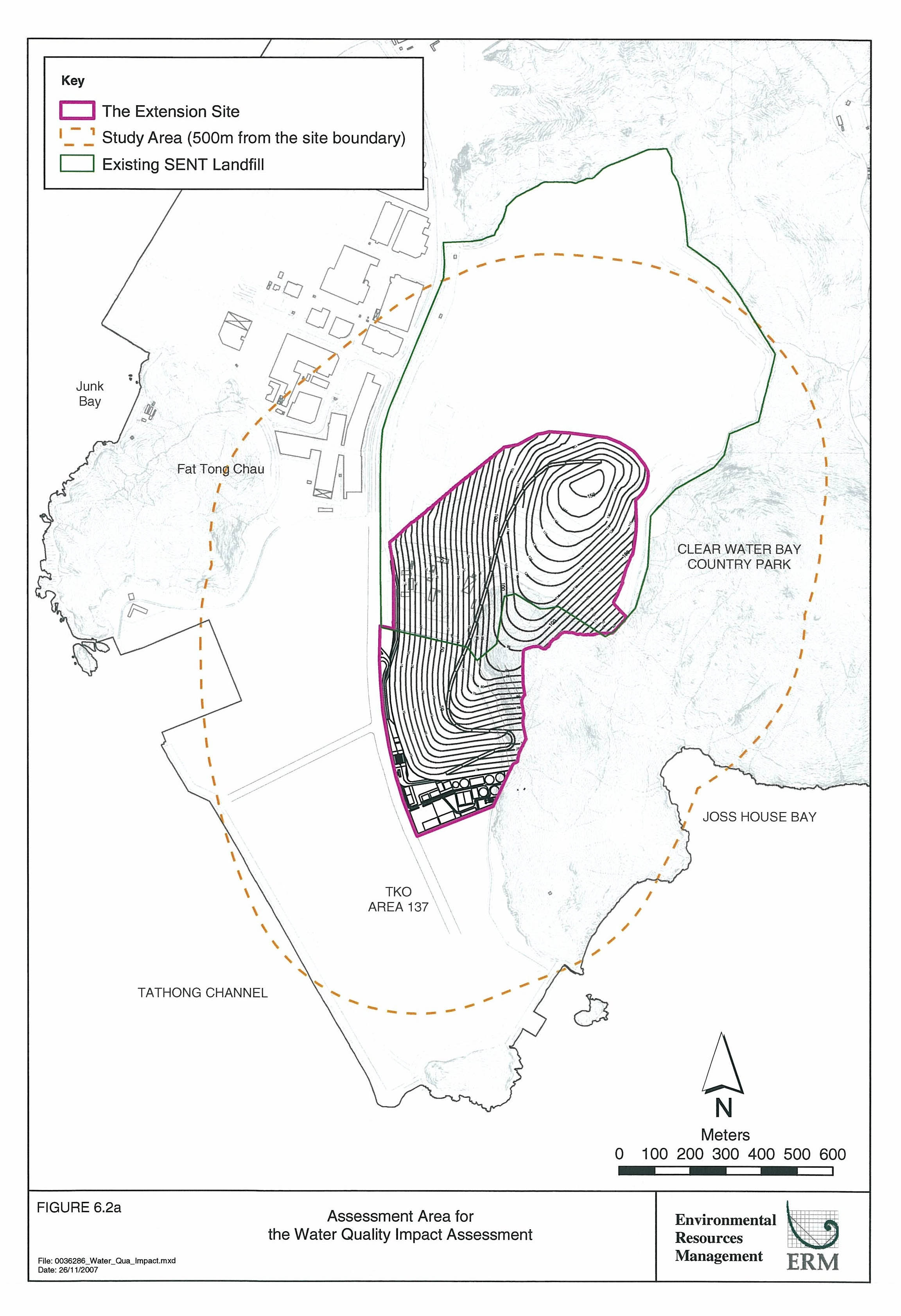
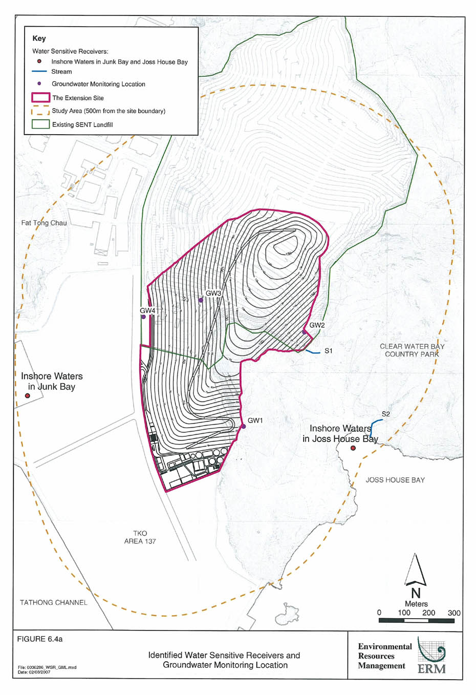
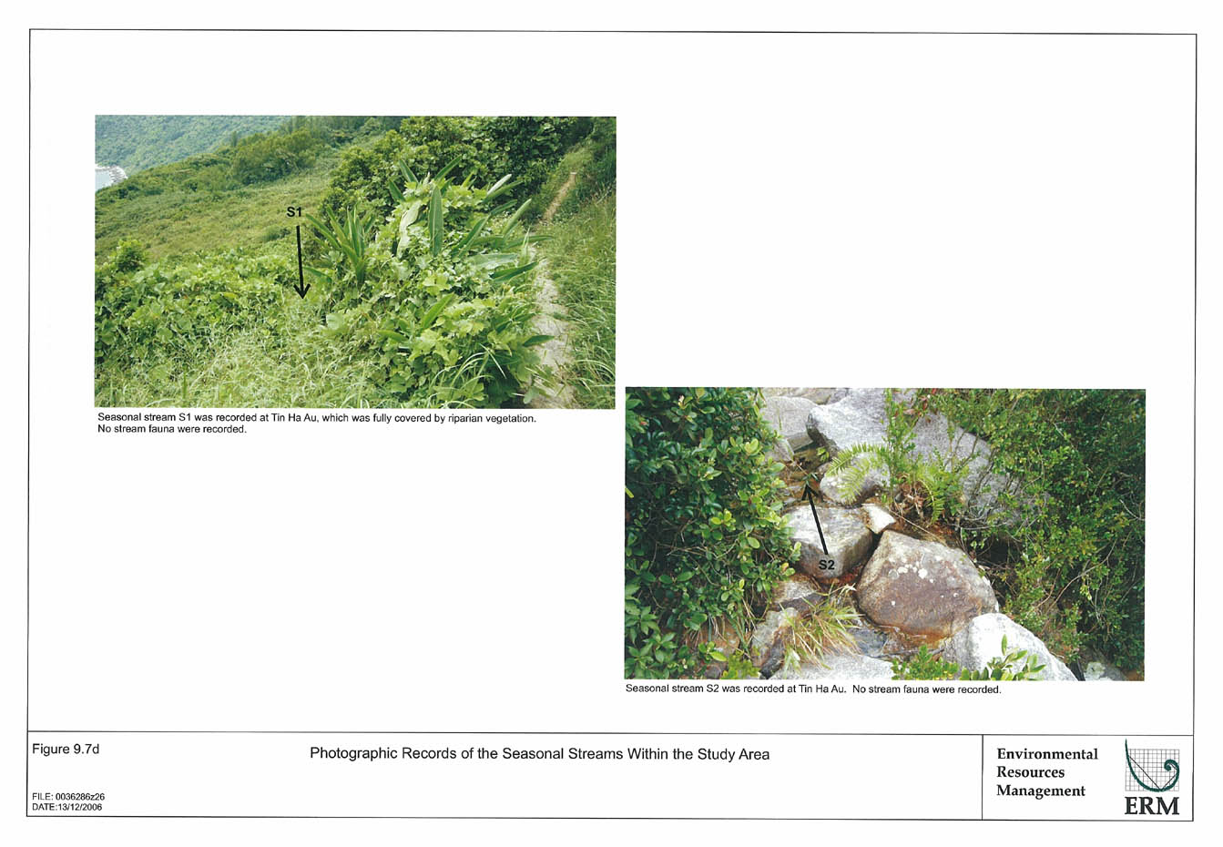
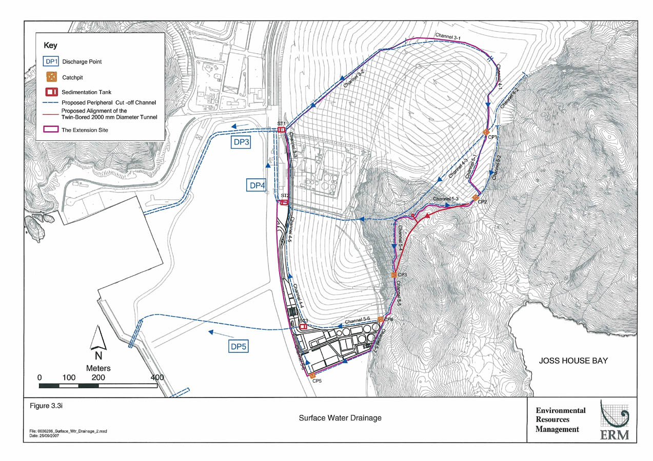
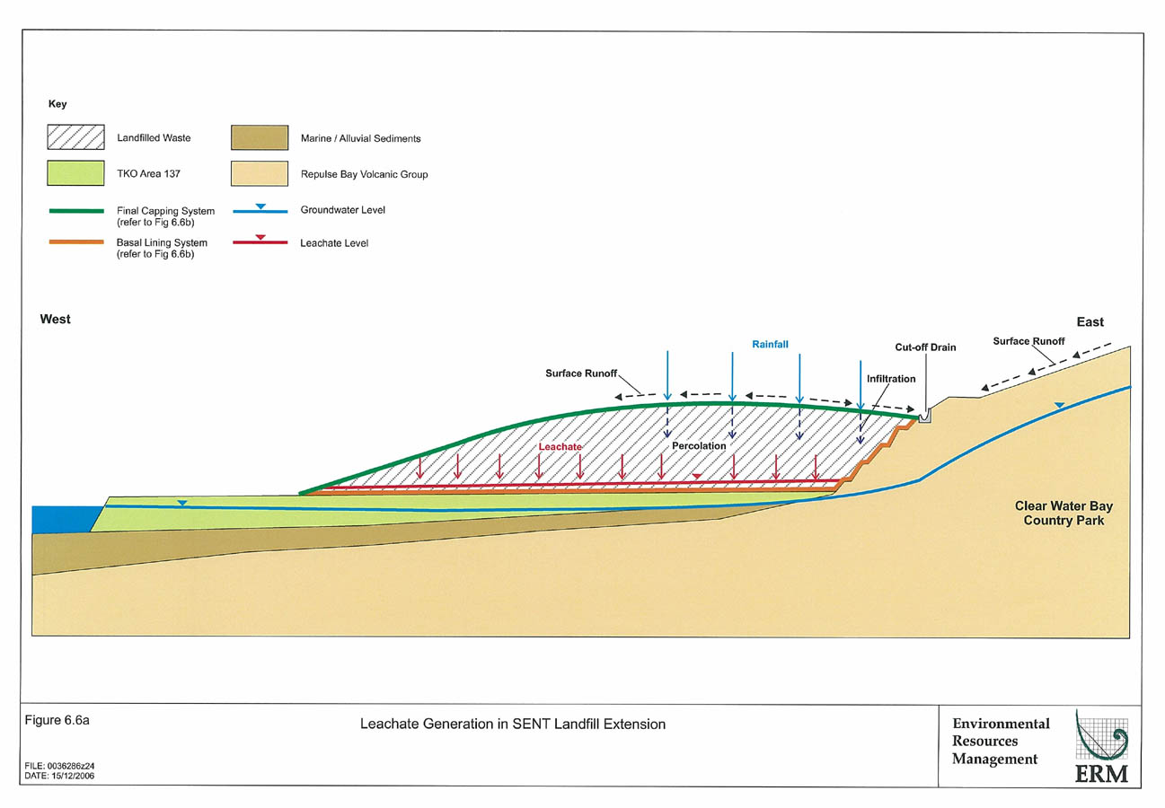
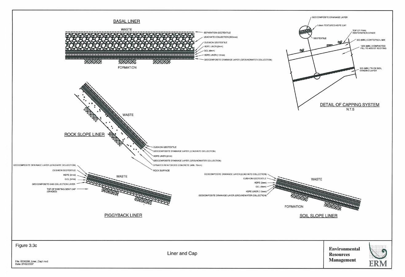
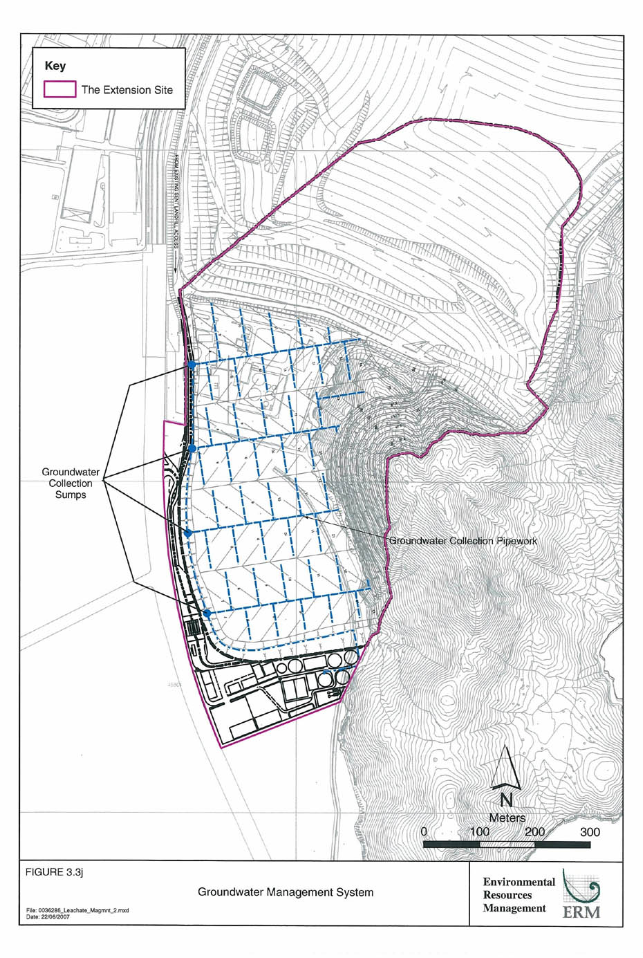