8.1.1
Background
The background to the EIA Study and the description
of the Project are provided in Sections 1 to 3 of this report.
This section presents the
methodology, findings and recommendations of the Hazard to Life assessment with
regard to the operation of the biodiesel plant.
8.1.2
Legislation
Requirement and Evaluation Criteria
The requirement for a Quantitative Risk
Assessment (QRA), for projects where risk to life is a key issue with respect
to Hong Kong Government Risk Guidelines (HKRG), is specified in Section 12 of
the Technical Memorandum on Environmental
Impact Assessment Process (EIAO-TM).
Annex 4 of the EIAO-TM specifies the Individual Risk and Societal Risk
Guidelines.
Individual Risk
Individual
risk is the predicted increase in the chance of fatality per year to a hypothetical individual who remains 100% of
the time at a given stationary point.
The
individual risk guidelines require that the maximum level of off-site
individual risk associated with a hazardous installation should not exceed 1×10⁻⁵
per year.
Societal Risk
Societal
risk expresses the risks to the whole population. The HKRG is presented
graphically in Figure 8.1a. It is expressed in terms of lines
plotting the frequency (F) of N or more deaths in the population
from incidents at the installation. Two FN risk lines are used in the HKRG to
demark “acceptable” and “unacceptable” societal risks. The intermediate region indicates the acceptability of societal risk is
borderline and should be reduced to a level which is “as low as reasonably
practicable” (ALARP). It seeks to ensure that all practicable and
cost-effective measures which can reduce risks will be considered.
Figure
8.1a Hong Kong
Government Risk Guidelines
8.1.3
Study
Objectives
The
objective of this risk study is to assess the risk to life of the general
public, including the workers of nearby plants, from the proposed facility
during its operational phase. The results of the QRA are compared with the
HKRG.
The detailed requirements of the study
(see Section 3.4.1.1 of the EIA study
brief) are as follows:
·
To
identify hazardous scenarios associated with the Project operation and then
determine a set of relevant scenarios to be included in a Quantitative Risk
Assessment (QRA);
·
To
execute a QRA of the set of hazardous scenarios identified, expressing
population risks in both individual and societal terms;
·
To
compare the individual and societal risks with the criteria for evaluating
hazard to life stipulated in Annex 4
of the EIAO-TM; and
·
To
identify and assess practicable and cost-effective risk mitigation measures.
As required in the EIA Study Brief,
the methodology used in this study is consistent with previous studies having
similar issues, in particular the PAFF EIA ().
This section summarises those aspects of the process
that are relevant to the risk assessment.
8.2.1
Plant Layout
The layout of the site is shown in Figure 8.2a.
The process and administration buildings are labelled as items 1A/1B/1C and are
located in the centre and towards the south of the site. The tank farm is
labelled as items 2A-2F and is situated on the north side. Storage tanks are
provided with impoundment bunds to contain any leaks from the tanks. The waste
water treatment plant (item 3) is situated on the west side of the site, as is
the jetty (item 4A) for loading/unloading of barges. The whole site will be
surrounded by a perimeter wall about 2m in height. Access to the site will be
through an entrance on Chun Wang
Street.
The process operations are carried out inside a
building, about 13m in height and 46m by 30m in area which is constructed of
concrete walls on two sides and steel structures with panels on the other two sides.
The building is provided with continuous ventilation as well as emergency
ventilation to prevent flammable atmosphere. All equipment and piping inside
the building are sealed and there are no continuous emissions inside the
building. The processing equipment is located inside a building to enable to
control the ambient temperature as well as for limiting the separation
distances imposed by the electrical area classification requirements.
According to the Hong Kong Code of Practice for Oil
Storage Installations, minimum separations are recommended
between adjacent tanks in a tank farm, and between tanks and buildings. In this
Code, combustible liquids are classified according to their flash point.
Separation requirements depend on the classification of the tank contents. In
the proposed plant, most tank contents would fall into Class 3 (lowest risk),
for which no separation requirements are specified. Only one tank, the methanol
storage tank T10, falls into Class 1 (highest risk), and this tank complies
with the layout requirements. It may be noted that although this Code applies
to petroleum products, reference to this Code was made based on the flash point
and boiling point of materials being handled in this project to determine the
adequacy of inter tank separation distances and bund capacities.
A process flow diagram and flow chart are shown in
Figure 8.2b and Figure 8.2c. A summary of the process will be
described below.
Figure
8.2a Site Layout
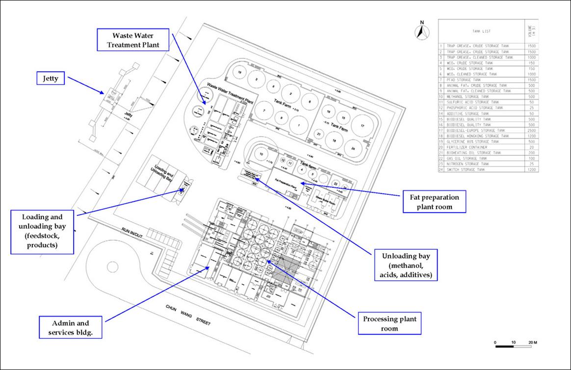
Figure 8.2b Process
Flow Diagram
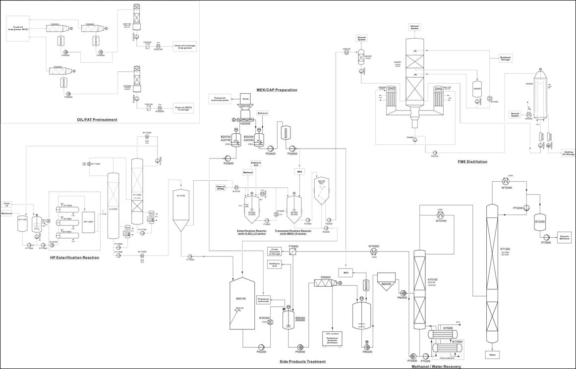
Figure 8.2c Process
Flow Chart

8.2.2
Transport Activities
Feedstock Reception and Handling
Grease trap waste (GTW), waste cooking oil
(WCO), gas oil, glycerine and other feedstock will be delivered by sealed 10 m3
road tankers or 10 tonne trucks.
Materials will be unloaded at the
designated stations as shown in Figure
8.2a. Four unloading bays will be provided. The GTW and WCO will be
unloaded via flexible hoses directly to the receiving tanks under a closed
system arrangement.
Typical fire safety measures including
spill containment, drainage of spills to a safe location, fire sprinkler
systems, fire detection systems, provision of means of firefighting including
hydrants and extinguishers, and adequate access for emergency services will be
provided. All tanker loading and unloading operations will be supervised by
trained personnel.
Jetty Operations
Palm Fatty Acid Distillate (PFAD) will be
delivered to site by barge and pumped from the barge to the storage tank.
Similar procedures will apply to the delivery of methanol and shipping out of
biodiesel. 1,000 tonne barges will be used for all marine-based transport. It
is estimated that about 2 barges per week will be required to transport
biodiesel out of the plant.
When
marine transport is not possible, e.g. due to adverse weather conditions,
biodiesel will be shipped out in 20 m3 road tankers (type D vehicles
for conveyance of Category 5 Dangerous Goods similar to those used for
transport of petroleum diesel). 10 trucks per day will be required to transport
biodiesel out of the plant.
The transportation of feedstock and
products to and from the biodiesel plant was tabulated in Table 3.2b and
is repeated here in Table 8.2a for convenience.
Table 8.2a Estimated
Number of Material Delivery to and from Biodiesel Plant
|
Material
|
Vehicle /
Barge
|
Frequency
|
|
Land-based
Delivery
|
|
|
|
Grease Trap Waste
|
10m3 Sealed Road Tanker
|
60(a) per day
|
|
Waste cooking oil
|
Trucks with 20ft containers
|
5 per day
|
|
Animal fat
|
10m3 Sealed Road Tanker
|
4 per day
|
|
Gas Oil
|
10m3 Sealed Road Tanker
|
1 per day
|
|
Glycerine
|
10m3 Sealed Road Tanker
|
2 per day
|
|
Fertilizer
|
10 tonne truck
|
1 per day
|
|
Nitrogen
|
10m3 Sealed Road Tanker
|
1 per week
|
|
Other supplies and deliveries
|
10 tonne Truck/Tanker
|
2 to 3 per day
|
|
Biodiesel (b)
|
20 m3 Road Tanker
|
10 per day
|
|
Methanol(b)
|
10m3 Sealed Road Tanker
|
2 per day
|
|
Total
|
|
76 to 89
|
|
Marine-based
Delivery
|
|
|
|
Biodiesel
|
1,000 tonne barge
|
2 per week
|
|
Palm oil fatty acid distillate
|
1,000 tonne barge
|
1 per 10 days
|
|
Methanol
|
1,000 tonne barge or ISO-tanker barge
|
1 per week
|
|
Total
|
|
4 per week
|
|
Notes:
(a)
GTW
will be delivered to the site on 24-hour basis.
(b)
Only
when marine transportation is not possible (eg during inclement weather).
|
8.2.3
Oil/Fat Preparation
Crude
oil/fat (grease trap waste, waste cooking oil, animal fats or palm oil fatty
acid distillate) which is part of the feedstock is cleaned from impurities in a
washing step by adding heated water and steam. The separation step is performed
by a series of decanters. Solids are collected in waste containers and the
aqueous phase is sent to the waste water treatment plant. The clean oil can
either be sent to oil drying columns for further treatment or pumped to the
storage tank in the tank farm area directly.
8.2.4
Esterification (with
catalyst)
The
esterification is a one step batch reaction under atmosphere pressure. This
reaction is used to convert free fatty acids (FFA) to methyl ester, which is the
main ingredient of biodiesel. In this process, FFA is esterified with methanol
to methyl ester and water under acidic conditions. The reaction is catalysed by
sulphuric acid and is operated at methanol’s boiling point with reflux
condensation. The esterification reactor is first filled with oil, then
methanol and sulphuric acid are added according to the recipe. The reactor is
heated by an internal heating coil. After the batch is completed, the agitator
is stopped and the water phase is allowed to settle before sending to the waste
water treatment. The oil phase is then cooled and pumped to the
transesterification reactor.
8.2.5
High Pressure
Esterification (without catalyst)
Feedstock
with a high concentration of Free Fatty Acids (FFA) is esterified with methanol
under high pressure and temperature rather than using the catalyst process.
This high pressure esterification reaction is a continuous process in a tubular
reactor jacketed by steam. The operating pressure of the reactor is 100 barg
and the temperature is between 180(C and 240(C. The reaction mixture consists
mainly of Fatty Acid Methyl Ester (FME), Glycerine, Methanol, Water,
Mono-/Di-/Triglyceride and FFA. Unused methanol and water are separated from
the oil phase in a demethanolisation dewatering column. Methanol and water are
further separated in a methanol water column and the methanol recovered for
reuse.
8.2.6
MEK Preparation
MEK
is a mixture of methanol and potassium hydroxide and acts as a catalyst for the
transesterification reaction. Methanol and potassium hydroxide combine to form
potassium methanolate (CH3OK).
8.2.7
Transesterification,
FME-Purification
The
transesterification reaction is used to convert triglycerides to methyl ester
and glycerine. The reaction is done in a two stage catalytic reaction with MEK.
Oil from esterification reactors (both with catalyst and without catalyst) is
pumped to the transesterification reactor. Fresh methanol, recycle methanol and
MEK (catalyst) are then added according to the recipe. The reaction mixture is
agitated for some time before the heavy glycerine phase (GLP) is allowed to be
settled at the bottom. The GLP is discharged to a buffer vessel for further
processing. Additional fresh methanol and MEK are added to the remaining
mixture and the second stage of the transesterification takes place. After
draining the GLP, the remaining content goes through a 3 stage washing
sequence.
Water
is added during the first washing step which helps separate the soap and
glycerine from the methyl ester. The aqueous phase is steeled and drained to
the GLP collection tank. Phosphoric acid is added to the transesterification
tank during step 2 of the washing sequence. This is mainly to convert potassium
soap back to FFA. The heavier phase is then partially discharged to the GLP collection
tank. At the third washing step, water is dosed to the vessel again to further
remove any remaining acid in the oil phase and improve the separation between
the lighter oil phase and the heavier phase. Finally the purified oil phase
(Methyl ester; Biodiesel) is discharged to the FME buffer tank.
8.2.8
FME Distillation
(including Vacuum System)
The
purified FME after the 3 washing steps still contains small amounts of methanol
and water. The FME is first heated to 200(C and then flashed to remove most of
the remaining methanol and water. The flash drum operates under vacuum
condition. The FME then enters 2 distillation columns which are both under
vacuum condition to allow moderate distillation temperatures (the two columns
operate at 230(C and 250(C). The final FEM contains 96.5% or higher methyl
ester. The distillate which contains other reaction by-products is used as
heating oil to fuel the column reboilers. The FEM is sent to the quality tank
where samples are taken to ascertain product quality. Provision is made to
route any off-spec product back to the feed for reprocessing.
8.2.9
Acidulation,
Phase-Separation
The
glycerine phase from the transesterification reactor is collected in the GLP
collection tank. A continuous stream from the collection tank is pumped to the
acidulation tank where it is mixed with the acidic water from the
esterification reactor, which contains sulphuric acid. Inside the acidulation
tank, potassium soap will react with acid and form potassium sulphate (solid
phase) and FFA. The reaction also produces 2 liquid phases (GLP and FFA).
Decanting is used to separate the 3 phases. The solid phase is discharged to
containers and sold as fertilizer, FFA is collected and recycled while the GLP
phase will be sent to the neutralization tank for further processing.
8.2.10
Neutralization
The
acidic glycerine phase (GLP) is collected in the neutralization tank where the
pH is adjusted to 7 by dosing with MEK. The solution is then filtered and
enters the demethanolization column.
8.2.11
Methanol and Water
Recovery
The
solution from the neutralization process, which contains glycerine, methanol
and water, is sent to the demethanolization column. Glycerine with small
amounts of water exit from the column bottom and are sent to the GLP storage
tank. Methanol and water from the top of the column are further separated in
the MET recovery column. Liquid methanol from the top of the MET recovery
column is collected in the recycle methanol tank and water from the bottom of
the column is sent to recycle water buffer tank. Both streams are reused in the
process.
8.2.12
Wastewater Treatment
Plant
Used process water from the Oil/Fat
preparation unit and the process areas are sent to the wastewater treatment
plant for treatment before routing to the public sewer. The key components of the
wastewater treatment plant will include an oil-water separator, a Dissolved Air
Flotation (DAF) system, an Internal Circulation (IC) Reactor (an anaerobic
treatment utilising up flow anaerobic sludge blanket (UASB) technology), an
aerobic treatment system and a secondary clarifier. The IC Reactor is an
anaerobic treatment technology that can effectively reduce the organic loading
of the wastewater, especially for wastewater with high organic matter content.
The biogas generated from the IC Reactor
has a high energy value and will be used as an energy source for on-site
facilities, namely as fuel for the steam boiler. The biogas will be temporarily
stored in a biogas buffer tank of 30 m3 capacity, under a pressure
of up to 5.5 kPa (0.055 barg). Under normal conditions, all biogas will be
consumed by the steam boiler. When the steam boiler is under maintenance, the
biogas will be sent to flare.
8.2.13
On-site Storage and
Ancillary Facilities
The steam boiler system will make use of towngas,
biogas, bioheating oil and biodiesel as energy sources for heating. It is
estimated that fuel consumption equivalent to about 8.4 tpd of biodiesel will
be required for the boiler system.
24 storage tanks are planned for the storage of
feedstock and products. The capacities of the tanks for various materials are
presented in Table 8.2b.
Table 8.2b Capacities
of Storage Tanks for the Biodiesel Plant
|
Tank Number
|
Description of Storage
Tank
|
No.
|
Capacity (m3)
|
Capacity
(Days)
|
|
1 & 2
|
Raw GTW Tank
|
2
|
1,500 each
|
4.6 (total)
|
|
3
|
Cleaned Trap Grease Tank
|
1
|
1,000
|
10.3
|
|
4 & 5
|
Dewatered GTW (Lipofit)
|
2
|
150 each
|
3.4 (total)
|
|
6
|
Cleaned WCO Tank
|
1
|
1,000
|
11.3
|
|
7
|
PFAD Tank
|
1
|
1,500
|
16.1
|
|
8
|
Raw Animal Fat Tank
|
1
|
500
|
11.2
|
|
9
|
Cleaned Animal Fat Tank
|
1
|
500
|
11.2
|
|
10
|
Methanol Tank
|
1
|
500
|
14.3
|
|
11
|
Sulphuric Acid
Tank
|
1
|
50
|
12.5
|
|
12
|
Phosphoric Acid
Tank
|
1
|
25
|
83.3
|
|
14
|
Additive
Storage Tank
|
1
|
50
|
15
|
|
15 & 16
|
Biodiesel
Quality Tank
|
2
|
500 each
|
3.2 (total)
|
|
17
|
Biodiesel
Storage Tank A
|
1
|
2,500
|
14.2
|
|
18
|
Biodiesel
Storage Tank B
|
1
|
1,200
|
9.2
|
|
19
|
Glycerine (80%)
Tank
|
1
|
500
|
30.2
|
|
20
|
Fertiliser
Container
|
1
|
20
|
2.6
|
|
21
|
Bioheating Oil
Tank
|
1
|
200
|
7.5
|
|
22
|
Gas Oil Tank
(as back up fuel)
|
1
|
100
|
8.3
|
|
23
|
Nitrogen Tank
|
1
|
25
|
16.5
|
|
24
|
Crude WCO Tank
|
1
|
1,200
|
-
|
8.2.14
Safety
Features
All vessels/tanks and other equipment for the biodiesel
plant will be designed to meet the applicable safety standards and to comply
with mechanical, technical and safety standards for chemical plant design and
local regulations. The entire production process will be program-controlled.
The process visualisation allows monitoring of the process and intervention if
required. The process equipment for the biodiesel production line (such as
vessels, machines, pipelines, instruments etc.) will be made of stainless steel
or other resistant materials fulfilling the respective mechanical, technical
and safety standards. The vessels and pipelines will be insulated by aluminium
plate. All vessels will be equipped with agitators and a manhole. Pumps for
methanol will be equipped with magnetic coupling to eliminate the problems of
leaking seals. All pumps will be monitored by a fully automatic process control
system (PCS) to prevent dry running.
Methanol will be stored in a carbon steel storage
tank with a double bottom layer and will be maintained at atmospheric pressure.
All process tanks and machines will be designed to be gas tight and equipped
with a gas displacement system. The whole system will have nitrogen blanketing
under positive pressure to prevent air ingress that may otherwise lead to the
formation of explosive gas mixtures. The methanol in the exhaust gas will be
removed in an air scrubber. A gas warning system will be installed to monitor
the methanol concentration inside the process room. The plant will shut down
automatically and the emergency ventilation system activated, if the monitoring
system detects a methanol concentration of 0.6% v/v inside the room.
The outdoor storage tanks will be built in a bunded
area where any spills can be contained. In most cases (some unlikely exceptions
are discussed in Section 8.3.2) the
impacts of fire caused by loss of containment to tanks would therefore be
confined to the bund area and minimise the damage to the surrounding
facilities. Bunds for acid storage tanks will be constructed with acid
resistant materials.
Explosion Protection
The entire plant is accomplished
with equipment according to the required explosion proof class. Open flames and
smoking are not permitted. For maintenance and repair works, non-sparking tools
will be used.
Each component in which the
concentration of methanol is high enough to form an explosive vapour is
connected to an inertisation system (ventilation system). Nitrogen is fed to
this system to reduce the oxygen content to an amount that no explosive vapour
mixtures are formed. Excessive vapour from this system is sent first to a
cooling trap in which the methanol is condensed, and then to an exhaust gas
washing column. The purified gas is ventilated through a vent above the roof of
the process plant.
Furthermore, rotating equipment in
which methanol vapour can be present is purged with nitrogen to avoid
explosions due to sparks in case of a possible malfunction of the equipment
internals.
Within the plant and near all
possible methanol emission sources (unloading station, methanol storage, etc.)
gas detection instruments will be installed. If gas is detected in the process
room, the emergency ventilation is activated automatically and an alarm is
displayed in the process control room. Each item of equipment is grounded by
proper connections to prevent electrostatic discharges.
Alarms & Shutdown
Every
deviation from normal operation condition is reported by the PCS by an alarm.
In case of an emergency the process can be stopped by one of the following shut
down procedures.
·
Loss
of utilities - In case of a loss of electrical supply, all electric equipment
stops. As the PCS is equipped with an uninterruptible power system, final
adjustments for safe shut down and preparation for easy recovery can be made.
There
are two redundant cooling pumps installed to maintain cooling. If deviations in
temperature occur, the units are shut down automatically by the PCS. In case of
complete loss of cooling water, the process is shut down. The cooling capacity
in the system allows a controlled shutdown without major evaporation of
methanol.
Loss
of instrument air or nitrogen automatically activates the protective shutdown
procedure.
·
Safety
pressure relief – Vessels and equipment are fitted with safety pressure relief
valves or rupture discs to protect against possible over pressurisation.
·
Other
measures - The plant will be protected by elaborate fire protection and fire
fighting systems.
8.2.15
Plant Personnel
Based on similar existing biodiesel plants,
the staffing requirements for the operation of the proposed biodiesel plant
will be about 20 in daytime and at least 8 at night time. If necessary,
external personnel will be hired for maintenance and repair works.
Since
the planning of the plant is at a relatively early stage, some plant documents
such as safety management system, emergency plan and maintenance system have
not yet been finalized. In this assessment, it is assumed that they will be
developed later in line with chemical process industry best practices.
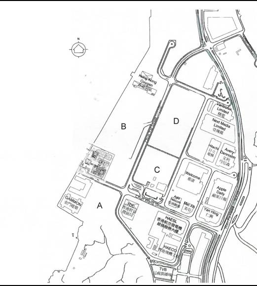
The proposed biodiesel plant will be
situated in the industrial estate of Tseung Kwan O, along the coast of Junk Bay (see Figure 8.3a).
Figure 8.3a Project
Site and its Surroundings

8.3.1
Population
Data
The vicinity of the
biodiesel plant is generally industrial, with the daytime population
significantly exceeding the night time occupancy. A Gammon warehouse and technology park lie to
the south, Hong Kong Oxygen about 400m to the north, and the Trade Development
Council to the east. Sites labelled as A, B, C and D are currently undeveloped.
The nearest high-rise residential buildings are those of the Dream City
development, about 800m to the north.
The population within the vicinity of the site was
estimated based on a combination of site visits, data provided by the Hong Kong
Science and Technology
Parks and company
websites. The maximum consequence distance from accidents at the facility was
calculated at about 300m and so all population within about 500m was considered
in the survey. A summary of the estimated population is given in Table 8.3a.
Table 8.3a Current
Population in the Vicinity of the Project Site
|
Site
|
Day Time Population
|
Night Time Population
|
|
|
Outdoor
|
Indoor
|
Outdoor
|
Indoor
|
|
Building
Population
|
|
|
|
|
|
Gammon Warehouse (North) (a)
|
5
|
45
|
1
|
9
|
|
Gammon Technology
Park (South) (a)
|
20
|
180
|
4
|
36
|
|
Hong Kong Oxygen (b)
|
23
|
207
|
5
|
41
|
|
TDC Warehouse (a)
|
30
|
270
|
6
|
54
|
|
Asia Netcom Landing Site 1 (a)
|
2
|
18
|
1
|
3
|
|
Asia Netcom Landing Site 2 (a)
|
2
|
18
|
1
|
3
|
|
HAESL (c)
|
65
|
585
|
13
|
117
|
|
Wellcome Warehouse (a)
|
25
|
225
|
5
|
45
|
|
Mei Ah (d)
|
21
|
189
|
4
|
38
|
|
HAECO (e)
|
37
|
333
|
7
|
67
|
|
Sub
Total
|
230
|
2070
|
47
|
413
|
|
|
|
|
|
|
|
Road
Population
|
|
|
|
|
|
Chun
Wang Street (550m) (f)
|
1.5
|
0
|
0.3
|
0
|
|
Chun
Yat Street (900m) (f)
|
23
|
0
|
4.7
|
0
|
|
Chun
Kwong Street (370m) (g)
|
1
|
0
|
0.2
|
0
|
|
Bus Terminal
|
10
|
0
|
2
|
0
|
|
Sub
Total
|
35.5
|
0
|
7.2
|
0
|
|
|
|
|
|
|
|
Marine
Population
|
|
|
|
|
|
Water Edge (f)
|
4
|
0
|
0.8
|
0
|
|
Junk Bay (f)
|
4
|
0
|
0.8
|
0
|
|
Sub
Total
|
8
|
0
|
1.6
|
0
|
|
|
|
|
|
|
|
Total
|
274
|
2070
|
56
|
413
|
|
Notes:
(a)
Populations are estimated based on a total population of
2300 people within 500m of the biodiesel plant. The judgement is based on a
site visit and functionality of the building.
(b)
Hoovers,
http://www.hoovers.com/Hong+Kong+Oxygen+&+Acetylene+Company+Limited/--HD__jxjfstyxx,src__global--/free-co-dnb_factsheet.xhtml
(c)
Hong Kong Aero Engine Services Ltd,
http://www.haesl.com/en_frame_facilites.html
(d)
Hoovers,
http://www.hoovers.com/Mei-Ah-Laser-Disc-Co-Ltd/--HD__jjyrcyxky,src__global--/free-co-dnb_factsheet.xhtml,
http://www.hoovers.com/Mei-Ah-Video-Production-Company-Limited/--HD__jxjshyxht,src__global--/free-co-dnb_factsheet.xhtml
(e)
Hong Kong Aircraft Engineering Company Limited
Environmental Report 2005,
http://www.haeco.com/company_update/HX%20Env%20report%202005.pdf
(f)
Estimated based on site visit carried out in September
2008. Eight barges were observed anchored within Junk Bay,
but no activity was observed on any of the barges. As a conservative
assumption, each barge was assumed to have a population of 5 persons indoors
giving a total population of 40. Given that the vessels will offer some
protection to their occupants, an exposure factor of 0.1 was used in the
analysis to give an effective outdoor population of 4.
(g)
The traffic density for Chun Kwong Street is assumed to be the
same as Chun Wang Street
which is 2.75 person/km
|
The night time worker
population has been assumed to be 20% of the daytime population. It is also
assumed that 90% of the workers would reside indoors, with the remaining 10%
being outdoors. A distinction between populations indoors and outdoors is made
because the buildings may offer some protection to their occupants from
accident scenarios such as fires. Population in vehicles are assumed to be all
outdoors.
A distinction is also made
between the daytime and night time populations, since significant differences
are to be expected. Daytime is defined as 8am to 6pm for 6 days a week and
night time from 6pm to 8am. Night time population is also assumed on Sunday.
The quoted population estimates represent the average over these time periods.
For marine
population, the population of 4 people is distributed evenly over the Junk Bay
area of 4km2 to derive a population density of 1 person/km2.
The water edge population of 4 is distributed evenly along the coast of the industrial
estate to give a line population.
The traffic populations on the Chun Yat Street and Chun Wang Street were measured during a
site visit. One hour of data was collected in the morning between 9am and 10am,
and an hour of data was collected in the afternoon between 2pm and 3pm. The
daytime traffic population was then calculated by assuming 2 hours of morning
traffic and 10 hours of afternoon traffic. Population estimates were obtained
by counting the number of vehicles of various types travelling in each
direction (Table 8.3b) and
multiplying by average occupancy estimates obtained from the Transport
Department Annual Traffic Census 2007(). These vehicle occupancy estimates are
based on cross harbour tunnel traffic and are likely to be conservative for
vehicles within the industrial estate.
Assuming an average speed of 20 km hr-1, the population density on the roads may
be calculated from:
Chun Yat Street
daytime population
=
 = 26 persons/km
Similar calculations were performed for Chun Wang Street to
give the road population figures presented in Table 8.3b. The site visit indicated that the bus terminal is quiet
with few people and so a population of 10 people present continuously was
conservatively assumed.
Night time road population is assumed to be 20% of
the day time population.
The current population within 500m from the biodiesel
plant was estimated by the Hong Kong Science and Technology Parks
at 2300. The population data summarised in Table
8.3c was determined so as to be in agreement with this estimate. The Tseung Kwan O Industrial Estate is expected
to undergo intensive development in the coming years. Once fully developed, the ultimate worker
population within 500m from the project site is estimated by the Hong
Kong Science and Technology
Parks at 5300. For the purpose of this assessment, these
additional 3000 people are assumed to be evenly spread (on a per unit area
basis) in the empty lots labelled as A, B, C and D in Figure 8.3a. The road and
bus terminal population are also increased proportionally. The future
population resulting from this analysis is summarised in Table 8.3c.
Following the above
discussion, this QRA study considers two population cases, corresponding to the
current and future population estimates. Results are presented for both cases
in Section 8.8.
Table 8.3b Traffic
Counts near the Project Site
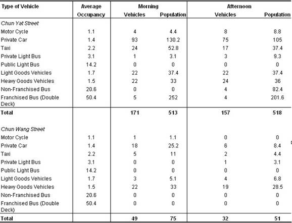

Table 8.3c Future
Population Estimates in the Vicinity of the Project Site
|
Site
|
Day Time Population
|
Night Time Population
|
|
|
Outdoor
|
Indoor
|
Outdoor
|
Indoor
|
|
Building
Population
|
|
|
|
|
|
Gammon Warehouse (North)
|
5
|
45
|
1
|
9
|
|
Gammon Technology Park (South)
|
20
|
180
|
4
|
36
|
|
Hong Kong Oxygen
|
23
|
207
|
5
|
41
|
|
TDC Warehouse
|
30
|
270
|
6
|
54
|
|
Asia Netcom Landing Site 1
|
2
|
18
|
1
|
3
|
|
Asia Netcom Landing Site 2
|
2
|
18
|
1
|
3
|
|
HAESL
|
65
|
585
|
13
|
117
|
|
Wellcome Warehouse
|
25
|
225
|
5
|
45
|
|
Mei Ah
|
21
|
189
|
4
|
38
|
|
HAECO
|
37
|
333
|
7
|
67
|
|
A
|
41
|
369
|
8
|
74
|
|
B
|
106
|
954
|
21
|
191
|
|
C
|
53
|
477
|
11
|
985
|
|
D
|
100
|
900
|
20
|
180
|
|
Sub Total
|
530
|
4770
|
107
|
1843
|
|
|
|
|
|
|
|
Road Population
|
|
|
|
|
|
Chun
Wang Street (550m)
|
3.5
|
0
|
0.7
|
0
|
|
Chun
Yat Street (900m)
|
53
|
0
|
10.6
|
0
|
|
Chun
Kwong Street (370m)
|
2.3
|
0
|
0.5
|
0
|
|
Bus Terminal
|
23
|
0
|
4.6
|
0
|
|
Sub Total
|
82
|
0
|
16
|
0
|
|
|
|
|
|
|
|
Marine Population
|
|
|
|
|
|
Water
Edge
|
4
|
0
|
0.8
|
0
|
|
Junk Bay
|
4
|
0
|
0.8
|
0
|
|
Sub Total
|
8
|
0
|
1.6
|
0
|
|
|
|
|
|
|
|
Total
|
620
|
4770
|
125
|
1843
|
8.3.2
Meteorological
Conditions
The consequences of accident scenarios, such as the
dispersion of flammable gases, depend on meteorological conditions of wind
speed, wind direction and atmospheric stability class. Hourly data were
obtained from the Tseung Kwan O weather station for the most recent 5 years
from 2003 to 2007. These weather data were then rationalised into different
combinations of wind direction, speed and atmospheric stability class and the
probability of occurrence for each combination determined (see Table 8.3d).
Table 8.3d Tseung
Kwan O Meteorological Data (2003-2007)
|
Direction
|
Percentage of Occurrence of each Wind Speed
(m/s)/Stability Category
|
|
|
Daytime (9am to 6pm)
|
Night time (6pm to 9am)
|
Total
|
|
|
1.5F
|
3B
|
3D
|
6D
|
1.5F
|
3B
|
3D
|
6D
|
|
|
N
|
0.61
|
2.3
|
1.78
|
0.29
|
12.13
|
0
|
3.79
|
0.8
|
21.69
|
|
NE
|
0.61
|
6.11
|
3.24
|
0.62
|
7.02
|
0
|
4.29
|
0.94
|
22.84
|
|
E
|
0.66
|
6.01
|
2.24
|
0.32
|
6.47
|
0
|
2.9
|
0.49
|
19.1
|
|
SE
|
0.23
|
1.5
|
0.51
|
0.08
|
3.48
|
0
|
0.96
|
0.19
|
6.95
|
|
S
|
0.19
|
5.63
|
0.96
|
0.12
|
2.68
|
0
|
1.29
|
0.2
|
11.06
|
|
SW
|
0.24
|
1.34
|
0.55
|
0.06
|
5.57
|
0
|
1.51
|
0.13
|
9.41
|
|
W
|
0.13
|
0.39
|
0.11
|
0.01
|
2.23
|
0
|
0.34
|
0.03
|
3.23
|
|
NW
|
0.15
|
0.32
|
0.19
|
0
|
4.64
|
0
|
0.41
|
0.01
|
5.73
|
|
Total
|
2.81
|
23.61
|
9.58
|
1.5
|
44.23
|
0
|
15.48
|
2.8
|
100
|
|
Note:
(a) Weather
condition 1.5F denotes wind speed of 1.5 m/s and atmospheric stability class
F. Similar notation applies to 3B, 3D and 6D.
|
Note on
Atmospheric Stability Class
The
Pasquill-Gifford atmospheric stability classes are defined as follows:
A: Turbulent;
B: Very unstable;
C: Unstable;
D: Neutral;
E: Stable; and
F: Very stable.
Atmospheric turbulence is a function of the vertical
temperature profile in the atmosphere; the greater the rate of decrease in
temperature with height, the greater the level of turbulence. The vertical
temperature profile generally depends on conditions of wind speed and cloud
cover.
Category A typically occurs in conditions of light
wind with strong solar insulation. This leads to rising air pockets, strong
vertical mixing and good dispersion characteristics. Stable atmospheric
conditions generally occur during light wind conditions, at night time with
clear skies. Radiative cooling of the ground leads to a reduced rate of
decrease of temperature with height, or even a temperature inversion. This
creates a stable atmosphere which inhibits vertical mixing and leads to poor
dispersion characteristics.
Category D is neutral and neither enhances nor
suppresses atmospheric turbulence. Conditions near class D usually occur during
stronger winds and/or overcast conditions.
To represent the range of meteorological conditions
possible at the Tseung Kwan O site, 4 weather conditions are considered in the
current study: 1.5F, 3B, 3D and 6D.
The
annual average temperature and relative humidity were taken to be 25(C and 70%
respectively.
The
methodology adopted for the risk assessment comprises the following major
elements which are discussed in detail in the following sections:
·
Hazard
Identification;
·
Consequence
Analysis;
·
Frequency
Estimation;
·
Risk
Summation and Evaluation; and
·
Risk
Mitigation (if necessary).
The
elements of a QRA are shown schematically in
Figure
8.4a. The study focuses on those hazardous
scenarios that have a potential to affect the off-site population.
Figure
8.4a Schematic
Diagram of QRA Process
8.5
Hazard
Identification
Material Safety Data Sheets (MSDS) were reviewed for
all materials handled on site, including feedstock, intermediate products,
products and by-products, so as to understand the potential hazards arising
from these substances. A summary of the relevant properties of these substances
is provided in Table 8.5a.
Methanol
Methanol is used as a reactant throughout
the biodiesel process. Methanol (CH3OH) is a highly flammable liquid
which burns with an invisible flame. Release can cause an immediate risk of
fire and explosion. Methanol is a volatile, clear, colourless liquid at ambient
conditions with weak alcohol odour.
Loss of containment of methanol may lead to
a bund/pool fire if ignited, or a flash fire if the dispersing vapour cloud
encounters an ignition source. If methanol vapour accumulates in a
congested/confined area, a vapour cloud explosion (VCE) may also occur.
Nevertheless, unlike most petroleum fires, methanol fires can be extinguished
with water.
Methanol is also mildly toxic. Acute
exposure by inhalation to high concentrations of methanol vapour can cause
irritation to mucous membranes, headaches, confusion, loss of consciousness and
even death.
Main Hazard: Highly flammable. Considered extremely flammable when stored
at elevated temperature above its boiling point of 64.5 (C.
Crude Oil
Crude oil is the main feedstock for
producing biodiesel. The main types of oil used are waste cooking oil (WCO),
grease trap waste (GTW), palm oil fatty acid distillate (PFAD) and animal fats.
The compositions of these oils are highly variable but consist mainly of
triglycerides and free fatty acids. They are viscous liquids or even solids at
ambient conditions. They have low vapour pressures, high flash points and high
boiling points. This means they are difficult to ignite although they are
combustible.
Main
Hazard: Combustible
Sulphuric Acid
Sulphuric Acid (H2SO4)
is a strong mineral acid and is highly corrosive. Pure sulphuric acid is an
odourless, clear, colourless, oily liquid. Sulphuric acid reacts violently with
water and the reaction is highly exothermic.
Sulphuric
acid is not considered toxic. Main occupational risks are skin contact leading
to burns and the inhalation of aerosols. Exposure to aerosols at high
concentration leads to immediate and severe irritation of the eyes, respiratory
tract and mucous membranes and may be fatal.
The reported lethal concentration LC50
for sulphuric acid through inhalation is 510mg/m3 for 2 hours
exposure in rats. LC50 for humans is estimated to be 625mg/m3
for 10 min exposure using Lee’s method ([4]).
The vapour pressure of sulphuric acid at room temperature (25(C) is less than
0.13 Pa which is equivalent to a saturated concentration of 5mg/m3.
This is much lower than the LC50. This suggests that a leak from the
sulphuric acid storage tank or other equipment near ambient temperature will not
pose any risk to personnel due to inhalation of vapours.
Process equipment containing sulphuric acid
at the highest operating temperature is the transesterification vessel at 72
(C. However, the acid is diluted to about 12% in this vessel and so the vapour
pressure will be correspondingly lower. For comparison, the vapour pressure of
pure acid at 50 (C is 0.4 Pa, corresponding to a concentration of 15 mg/m3,
still significantly lower than the LC50. In conclusion, the vapour
pressure of sulphuric acid is insufficient to cause dangerous concentrations of
vapours and hence sulphuric acid is not considered hazardous to offsite
population.
Main Hazard: No significant hazard offsite
Phosphoric Acid
Phosphoric Acid (H3PO4)
is a strong mineral acid and is a white powder under normal conditions.
Phosphoric acid solution is corrosive and may cause severe respiration tract,
digestive tract, eye and skin irritation with possible burns. Phosphoric acid
is non-toxic and non-combustible.
Phosphoric acid has similar properties as
sulphuric acid. The reported lethal limit LC50 through inhalation is
850mg/m3 for 1 hour exposure in rats. LC50 for humans is
estimated to be 520mg/m3 for 10 min using Lee’s method. The vapour
pressure of phosphoric acid is 0.044 Pa at 25 (C, rising to 1.3 Pa at 80 (C.
The maximum vapour concentration at process temperatures of 72(C was estimated
at 26 mg/m3, much lower than the LC50. In conclusion, the
vapour concentration in air is too low to present any hazards to people
offsite.
Main Hazard: No significant hazard offsite
Sodium Hydroxide
Sodium hydroxide (NaOH) is a white solid
and forms a strong alkaline solution when dissolved in water with liberation of
heat. Sodium hydroxide is corrosive and can cause eye and skin burns. Potential
severe respiratory tract, digestive tract irritation with possible burns and
damage to mucous membranes. Irritation may lead to chemical pneumonitis and
pulmonary edema. Sodium hydroxide is non-toxic and non-combustible.
Although sodium hydroxide has a lethal limit
LC50 of 2300 mg/m3/2H (rats), sodium hydroxide is
extremely non-volatile. The vapour pressure of sodium hydroxide is 1 mmHg (132
Pa) at 739 (C at which is still well below the lethal limit.
Main Hazard: No significant hazard offsite
Potassium Hydroxide
Potassium hydroxide (KOH) is a white solid
and forms a strong alkaline solution when dissolved in water with liberation of
heat. It has similar properties as sodium hydroxide. Potassium hydroxide is
corrosive and can cause eye and skin burns. Potential severe respiratory tract,
digestive tract irritation with possible burns and damage to mucous membranes.
Irritation may lead to chemical pneumonitis and pulmonary edema. Potassium
hydroxide is non-toxic and non-combustible.
Main Hazard: No significant hazard offsite
Additive (Infineum R408)
Infineum R408 is being added to the
biodiesel to enhance its combustion properties. Infineum includes the following
hazardous ingredients: solvent naphtha, distillates (hydrotreated light),
kerosene, alkylhydroxybenzoate formaldehyde condensate, vinyl acetate,
mesitylene, 1,2,4-trimethylbenzene, naphthalene. Inhalation of vapours from the
heated product can cause irritation of the respiratory tract and the eyes. It
has a flash point of 62(C.
Main Hazard: Flammable
Monoglycerides and Diglycerides
Monoglycerides and diglycerides are the
side products generated during the esterification and transesterification
process. They have similar properties as biodiesel and are combustible under
normal conditions. They pose a minor health hazard including
skin/eye/respiratory tract irritation on contract.
Main Hazard: Combustible
Triglyceride
Triglyceride (more properly know as
triacylglycerol, TAG or triacylglyceride) is a glyceride in which the glycerol
is esterified with three fatty acids. It is common in both vegetable oil and
animal fats. The melting point of triglyceride is heavily depending on the
length of the fatty acid molecule. Triglyceride with a carbon chain longer than
10 carbons atoms would most likely be a solid at room temperature.
Main Hazard: Combustible
Glycerine
Glycerine is generated during the
transesterification reaction. It is a colourless, clear liquid without odour.
Glycerine poses a minor health hazard including skin/eye/respiratory tract
irritation on contract. It has a rather high flash point, giving it a
classification of ‘combustible’.
Main Hazard: Combustible
Potassium Phosphate Monobasic
Potassium phosphate monobasic is an
intermediate product. Pure potassium phosphate monobasic is a white crystalline
solid. Inhalation or ingestion may cause respiratory and digestive tract
irritation.
In the biodiesel production process, this
material only appears in a few streams with a maximum concentration of 5%wt. No
significant hazards have been identified.
Main Hazard: No significant hazard offsite
Biodiesel
Biodiesel is a non-toxic chemical. The main
composition of the biodiesel is methyl ester (over 96%). Biodiesel has a very
high flash point of over 125 °C and is not volatile. It is therefore considered
as combustible rather than flammable. Biodiesel poses a minor health hazard
including skin/eye/respiratory tract irritation on contract.
Main Hazard: Combustible
Biogas
Biogas is generated from the IC
reactor in the water treatment plant. Biogas is temporarily stored in the
biogas buffer tank of 30 m3. Biogas consists mostly of
methane and its properties are very similar to Natural Gas (NG). While it is
non-toxic, in high concentrations it could lead to asphyxiation. A loss of
containment can lead to jet fire (if stored/transferred under sufficient
pressure) or to an explosion if the gas accumulates in a confined space.
Main
Hazard: Extremely Flammable
Potassium Sulphate (fertiliser)
Potassium
Sulphate is a by-product from neutralizing sulphuric acid with potassium
hydroxide during the side product treatment step. No specific hazards are
identified for potassium sulphate. It is non-toxic, non-flammable, and
non-combustible ().
Main
Hazard: None
Gas oil and Bioheating oil
Gas oil and bioheating oil are used as supplementary fuel in the
biodiesel plant to operate various process equipment such as boilers. It
contains medium sized hydrocarbons (C9-C20) and has similar fire properties to
biodiesel. Gas oil is, however, bunded separately since unlike biodiesel, gas
oil is not biodegradable.
Main
Hazard: Combustible
Other Chemicals
Other chemicals involved in the biodiesel
process includes Sodium Sulphate and Nitrogen and are considered to pose
negligible risk to the offsite population and only a minimal risk to the
on-site work-force.
Based on the
list of materials on site, potentially hazardous materials identified include
Methanol, Crude oil, Infineum R408 (additive), Mono-/di-/tri- Glycerides,
Glycerine, Biodiesel, Gas oil/Bioheating oil and Biogas. These
are considered further in the analysis.
Table
8.5a Key Properties of Chemicals
|
Chemical
|
CAS #
|
Normal State
|
Molecular Formula
|
MW
|
Vapour
Pressure (kPa)
|
Vapour
Density (Air =1)
|
Melting
Point ((C)
|
Boiling
Point ((C)
|
Flash
point ((C)
|
Auto-ignition Temperature ((C)
|
Flammability
Limit (%)
|
LC 50
|
Main
Hazard
|
|
|
|
|
|
|
UFL
|
LFL
|
|
|
|
Feedstock
|
|
|
|
|
|
|
|
|
|
|
|
|
|
|
|
Methanol
|
67-56-1
|
Liquid
|
CH3OH
|
32.04
|
12.8
|
1.11
|
-98
|
64.5
|
11
|
455
|
36.5
|
5.5
|
64000ppm /4 hrs (rat)
|
Highly
Flammable[1]
|
|
Crude Palm Oil Fatty Acid (PFAD)
|
-
|
Liquid
|
-
|
-
|
<1
|
-
|
-
|
> 200
|
> 200
|
> 250
|
-
|
-
|
-
|
Combustible
|
|
Free Fatty Acid
|
67254-79-9
|
Liquid
|
-
|
-
|
-
|
-
|
-
|
> 200
|
315
|
400
|
-
|
-
|
-
|
Combustible
|
|
Animal Fat (mainly triglycerides)
|
-
|
Solid
|
-
|
-
|
-
|
-
|
35
|
-
|
274
|
-
|
-
|
-
|
-
|
Combustible
|
|
Sulphuric Acid (solution)
|
7664-93-9
|
Liquid
|
H2SO4
|
98.08
|
0.00013
|
3.4
|
-15
|
310
|
-
|
-
|
-
|
-
|
510 mg/m3 /2 hrs (rat)
|
None
|
|
Phosphoric Acid (solution)
|
7664-38-2
|
Liquid
|
H3PO4
|
98
|
0.0038
|
-
|
-20
|
158
|
-
|
-
|
-
|
-
|
850 mg/m3 /1 hr (rat)
|
None
|
|
Sodium Hydroxide
|
1310-73-2
|
Solid
|
NaOH
|
40
|
-
|
-
|
318
|
1390
|
-
|
-
|
-
|
-
|
2300 mg/m3 /2 hr (rat)
|
None
|
|
Potassium Hydroxide
|
1310-58-3
|
Solid
|
KOH
|
56.1
|
-
|
-
|
380
|
1384
|
-
|
-
|
-
|
-
|
-
|
None
|
|
Infineum R408
(additive)
|
-
|
Liquid
|
~20% Naphtha, ~5%
Petroleum Distillates, ~5% Kerosene, ~5% Alkylhydroxybenzoate, formaldehyde
condensate
|
-
|
-
|
-
|
-
|
-
|
62
|
-
|
-
|
-
|
-
|
Flammable
|
|
Intermediate Products
|
|
|
|
|
|
|
|
|
|
|
|
|
|
|
Mono/Di
Glycerides (Glyceryl Mono – Dicaprylate)
|
26402-26-6
|
Solid
|
-
|
-
|
<0.27
|
-
|
34
|
155
|
180
|
-
|
-
|
-
|
-
|
Combustible
|
|
Monoglyceride
(distilled)
|
97593-29-8
|
Solid
|
-
|
-
|
-
|
-
|
-
|
250
|
100
|
-
|
-
|
-
|
-
|
Combustible
|
|
Triglycerides
|
85665-33-4
|
Solid
|
-
|
-
|
-
|
-
|
34
|
-
|
200
|
-
|
-
|
-
|
-
|
Combustible
|
|
Glycerine
|
56-81-5
|
Liquid
|
CH2CHOHCH2OH
|
92.1
|
< 0.01
|
3.1
|
-
|
171
|
199
|
370
|
-
|
-
|
-
|
Combustible
|
|
Potassium
Phosphate Monobasic
|
7778-77-0
|
Solid
|
KH2PO4
|
136.08
|
-
|
-
|
252.6
|
-
|
-
|
-
|
-
|
-
|
-
|
None
|
|
|
|
|
|
|
|
|
|
|
|
|
|
|
|
|
|
Products/By-products
|
|
|
|
|
|
|
|
|
|
|
|
|
|
|
Methyl Ester (Biodiesel) [2]
|
67784-80-9
73891-99-3
61788-71-2
|
Liquid
|
-
|
-
|
<0.27
|
> 1
|
-
|
> 200
|
130
|
-
|
-
|
-
|
-
|
Combustible
|
|
Biogas [3]
|
8006-14-2
|
Gas
|
CH4
|
-
|
-
|
0.59 to 0.72
|
-182.5
|
-161.4
|
-188
|
580
|
5
|
15
|
-
|
Extremely Flammable
|
|
Potassium Sulphate (fertilizer)
|
7778-80-5
|
Solid
|
K2SO4
|
14.26
|
-
|
-
|
1067
|
1689
|
-
|
-
|
-
|
-
|
-
|
None
|
Notes:
All data are measured at standard state of 20(C and 101kPa.
Flammability classification is according to COMAH guideline (1999 No.
743); Combustible classification is according to OSHA guideline:
· Flammable:
Any substance having a flash point higher than 20 (C and lower than 55(C
· Highly
Flammable: Substances having a flash point lower than 21(C which are not
extremely flammable, or substances which have a flash point lower than
55(C and which remain liquid under pressure, where particular processing
conditions such as high pressure or high temperature may create major accident
hazards.
· Extremely
Flammable: Any substance having a flash point lower than 0(C and boiling point
less than 35 (C or flammable substance maintained above their boiling
point or gaseous substances that are flammable at ambient temperature
and pressure.
· Combustible:
Any substance having a flash point above 100(C.
[1] Methanol is highly flammable for storage at ambient temperature. For
handling at elevated temperatures in the process areas, it will be classed as
extremely flammable if the temperature exceeds the boiling point.
[2] Methyl ester is a group of similar chemicals. Depending on the raw
material, different methyl ester will be produced. The three CAS numbers given
are associated with the typical biodiesel produced from a combination of animal
fats and vegetable oil.
[3] The properties of biogas are very similar to those of Natural Gas
(NG), therefore the data for NG is presented.
8.5.2
Review
of Previous Incidents
To investigate further the possible hazards from the
biodiesel plant, a review of past incidents at similar facilities worldwide was
conducted. This involved the review of accident databases such as MHIDAS and
the IChemE Accident Database, as well as internet searches.
Incidents at Same Technology Plants
The proposed biodiesel plant in Tseung Kwan O uses
the Biodiesel International (BDI) Technology. There are currently 28 biodiesel
plants in Europe using the same technology with
a combined plant experience of about 280 plant-years. To date, no noteworthy
incidents have occurred at any of the plants, demonstrating an excellent safety
record. However, the sample size is not large enough to derive a statistically
significant incident frequency for comparison with the EIAO-TM risk
guidelines.
Incidents at Other Biodiesel Plants
A review of incidents at other biodiesel plants is
provided in Table 8.5b. It can be seen that most incidents are related
to ignition of methanol vapours although some fires also occurred involving
biodiesel and vegetable oil. Further fire incidents relating to methanol are
listed in Table 8.5c. A detailed consideration of previous incidents and
their relevance to this study is given below, in later paragraphs.
Biodiesel production in both Europe and the US is growing
rapidly. In Europe,
for example, one estimate puts the number of plants in operation in
2006 at 65, while another report shows European output growing at more than
50% per year. The European biodiesel
industry has an excellent safety record, with no major incidents reported in
recent years.
We have also considered the US biodiesel industry, which has experienced a
number of plant incidents, unlike in Europe,
as shown in the following table. According
to some estimates, there could be as many as 200 biodiesel
plants in the USA at present, although many of these are likely to be small
scale and/or idling (as discussed later in this report). Based on this, we
could assume approximately 600 plant years of experience in the US.
As shown in the incident reports below, there have
been 3 incidents leading to fatalities onsite in the USA in recent years (although no
offsite fatalities). Once again, the
sample size is not large enough to determine a statistically significant
accident frequency but the data may be used to derive an upper bound. There is
evidence to suggest a significant difference in the operating philosophy of
biodiesel plants in Europe and the US.
Whereas in Europe, plants are managed
by professionals experienced in chemical processing, US plants often grow
organically from ‘backyard’ or entrepreneur start-up operations. This results in substantial differences in
the way the plants are operated and managed.
To reflect this, we have investigated the recent incidents in more
detail, with the aim of examining their relevance to the proposed plant. This has enabled us to obtain a rough
quantitative estimate of the incident frequency in the proposed plant, for
comparison with the QRA results, as described in the following section.
Diesel Tanker Related Incidents
A search for incidents relating to diesel road
tankers produced the results shown in Table 8.5d. Although several
incidents resulted in fuel release, in none of the case was the fuel ignited.
This demonstrates that the probability of ignition of diesel fuel is rather low
due to its high flash point. The properties of biodiesel are similar to
petroleum diesel.
Following this review of past incidents, the main
hazard is associated with explosions and fires from methanol due to its low
flash point. This QRA study therefore looks at possible methanol incidents in
detail, and also the possibility of fires from other flammable/combustible
materials.
Tank Failures
Table 8.5e provides a list of storage tank failures. The causes
are mostly mechanical failure and corrosion. One case was caused by earthquake.
It is interesting to note that in at least 2 cases, the bund failed to contain
the whole inventory.
Tank failure and the possibility of bund overtopping
is considered in the current assessment.
Table
8.5b Previous Incidents Involving
Biodiesel Plants and Related Materials
|
Date of
incident
|
Location of
incident
|
Material
Name
|
Incident
Type
|
Injuries/
Fatalities
|
Description
|
Reference
|
|
15/08/2008
|
DECATURVILLE, TENNESSEE,
USA
|
|
Fire; Explosion
|
0 Injured
0 Killed
|
An explosion
took place in a standby biodiesel plant awaiting conversion to glycerine
production. The explosion and fire destroyed all the existing stocks of
biodiesel, sodium hydroxide, methanol and glycerine. No injury is reported
|
1
|
|
18/05/2008
|
PRINCESS ANNE, MD,
USA
|
METHANOL/
Biodiesel
|
Fire; Explosion
|
1 Injured
1 Killed
|
2 worker were
installing a new methane line at the facility when a massive explosion
occurred which blew the walls of the building out and bubbled the roof out.
One worker died and the other one injured
|
2
|
|
15/04/2008
|
CALGARY, CANADA
|
METHANOL
VAPOR
|
Fire; Explosion
|
0 Injured
1 Killed
|
A worker died in
an explosion at a biodiesel plant while carrying out welding operation on top
of a 30-ft biodiesel settling tank. Fumes and methanol accumulated inside the
tank ignited by the welding operation caused the explosion. Fire continued to
burn in the tank for several hours until all the biodiesel is consumed
|
3
|
|
04/01/2008
|
DEFIANCE, OHIO,
USA
|
METHANOL
VAPOR
|
Fire; Explosion
|
3 Injured
0 Killed
|
Operator in the
biodiesel plant left a manhole cover open on a storage tank holding glycerin,
and a spark from an electric motor ignited the methanol vapors that escaped.
Three workers inside the biodiesel plant were hurt.
|
4
|
|
07/07/2006
|
NEW PLYMOUTH, IDAHO,
USA
|
METHANOL
VAPOR/ BIODIESEL VAPOR
|
Explosion
|
2 Injured
1 Killed
|
Two explosions
happened while one worker was working on top of a tank used to store soy oil.
One worker was killed, one suffered 2nd degree burn and another
suffered from smoke inhalation. Nearby highway was shut down for 4 hours.
|
5
|
|
17/02/2006
|
BAKERSFIELD, CA,
USA
|
METHANOL
|
Fire
|
0 Injured
0 Killed
|
The accident happened outside of the
plant building when, during a transfer of methanol, a small spill occurred
that ignited (ignition source unknown, probable cause static electricity).
The plant was in full production mode when the outside fire spread into the
building. The operators followed their training and safety procedures and
quickly shut down operations. Then, when they could not contain the fire with
on-site extinguishers, they left the premises and quickly notified the Fire
Department and Hondo personnel in the other buildings located on the
property. No other buildings were affected because they were not in close
proximity. Unfortunately, ABF suffered a total loss of the building and
equipment. The plant burned violently for several hours and the non-hazardous
plumes of smoke could be seen for miles. As a result, although the entire
plant was destroyed: five biodiesel tanks (containing approx. 30,000 gallons)
and 6,000 gallons of methanol were saved; and, approx. 90,000 gallons of corn
oil stored in railroad cars were moved back safely with only some minor fire
damage to the exterior of the cars.
|
6
|
|
03/11/1997
|
ISRAEL
|
DIESEL
|
Fire; Explosion
|
0 Injured
1 Killed
|
A fire occurred in a diesel storage tank
following explosion and caused a fatality. Worker had gone for a test sample
when the explosion occurred
|
IChemE
|
|
11/01/1995
|
USA; TENNESSEE; CHATTANOOGA
|
VEGETABLE OIL
|
Fire
|
Not reported
|
Derailment of
twenty cars of freight train. Box car containing half gallon containers of
vegetable oil was first to catch fire.
|
MHIDAS
|
|
03/06/1988
|
Izmir, TURKEY
|
VEGETABLE OIL
|
Ship to shore
impact
|
0 Injured
0 Killed
|
A marine transportation incident. A
marine tanker hit berth at a terminal while manoeuvring in to discharge
vegetable oil. Bow heavily damaged. Jetty destroyed.
|
IChemE
|
|
10/11/1979
|
NORWAY; SKREIA
|
VEG OIL + SODA
|
Runaway-reaction
|
0 Injured
0 Killed
|
Chemical
reaction between vegetable oil and soda. Violent explosion destroyed 2-Storey
building of area 25,000m2.
|
MHIDAS
|
|
10/02/1970
|
FRANCE; MARSEILLES
|
VEGETABLE OIL
|
Fire; Explosion
|
12 Injured
2 Killed
|
Explosion in
vegetable oil refinery of a soap factory. Refinery gutted by fire.
|
MHIDAS
|
1: http://www.biofuels-news.com/news/tennessee_explosion.html
2: http://wjz.com/local/bio.diesel.plant.2.726871.html
3:
http://www.cbc.ca/canada/calgary/story/2008/04/15/biodiesel-explode.html
4: http://www.indianasnewscenter.com/news/local/13062367.html
5:
http://www.idahobusiness.net/archive.htm/2006/07/17/What-Now-Explosion-at-New-Plymouth-biodiesel-plant-raises-questions-for-highlytouted-market
6:
http://www.greaseworks.org/modules.php?op=modload&name=News&file=article&sid=274&mode=thread&order=0&thold=0
Table
8.5c Previous Incident Involving
Methanol
|
Date of
incident
|
Location of
incident
|
Material
Name
|
Incident
Type
|
Injuries/
Fatalities
|
Description
|
Reference
|
|
20/02/2001
|
USA; ALASKA;
PRUDHOE BAY
|
METHANOL
|
Continuous-release
|
0 Injured
0 Killed
|
Water frozen in oil pipeline creating an
ice plug. Pipeline flushed with warm crude oil and methanol, and pressure
raised to help melt the ice. The oil and methanal leaked from a crack on the
top of the pipeline. Size of spill unclear.
|
MHIDAS
|
|
06/12/2000
|
USA; NEW
MEXICO; JAL
|
METHANOL
|
Fire
|
Not reported
|
A natural gas pipeline ruptured and
exploded underneath two storage tanks containing methanol and glycol. The
tanks burned out and the plant was forced to close.
|
MHIDAS
|
|
05/11/2000
|
USA; TEXAS;
SONORA
|
METHANOL
|
Fire
|
0 Injured
0 Killed
|
Lightning struck a transformer, igniting
a chemical warehouse. All residents within half a mile were evacuated. Fire
was extinguished within three hours. Warehouse contained methanol, cleaning
solvents and other hazardous chemicals.
|
MHIDAS
|
|
04/09/2000
|
UK; ESSEX;
PURFLEET
|
METHANOL
|
Continuous-release
|
0 Injured
0 Killed
|
19,000 kg of methanol spilled out onto
the dock side after a container loaded with the solvent toppled over. The
area was cordoned off by police to allow specialists to remove the chemical.
The wharf was cleared of all shipping as a precaution.
|
MHIDAS
|
|
14/03/2000
|
UK; NORFOLK;
NORWICH
|
METHANOL
|
Release
|
0 Injured
0 Killed
|
Workers were evacuation after a single
container of chemical leaked in a warehouse. It is unclear whether the
chemical was sulphuric acid or methanol. Fire fighters cleaned up and made
safe the leaking container.
|
MHIDAS
|
|
19/08/1999
|
UK; WEST MIDLANDS; WEST
BROMWICH
|
METHANOL
|
Gas-cloud
|
0 Injured
2 Killed
|
2 night watch men found dead when day
shift arrived. They were overcome by fumes believed to be form mixture of
methanol, potassium powder & hydrochloric acid, used to strip wheels.
High levels of methylene chloride traced in building.
|
MHIDAS
|
|
30/03/1998
|
UK; CHESHIRE;
ELLESMERE PORT
|
METHANOL
|
Fireball
|
Not reported
|
Tanker carrying
20 tonnes methanol overturned on a roundabout and caught fire. Methanol burns
invisibly and fireball was recorded on a thermal imaging camera in a police
aircraft which helped direct evacuation and firefighting. Motorway closed for
6 hours.
|
MHIDAS
|
Table 8.5d Previous
Incident Involving Diesel Tankers
|
Date of
incident
|
Location of
incident
|
Material
Name
|
Incident
Type
|
Injuries/
Fatalities
|
Description
|
Reference
|
|
29/10/1998
|
UK; MID GLAMORGAN; PENCOED
|
DIESEL FUEL
|
Continuous-release; Liquid pool formed
|
0 Injured
0 Killed
|
A Diesel tanker and a gas tanker collided on the M4
spilling hundreds of gallons of diesel. The motorway was blocked for more
than 6 hours. Fire fighters undertook a huge mopping up operation. Both
drivers were uninjured.
|
MHIDAS
|
|
09/07/1998
|
UK; DEVON;
CULLOMPTON
|
DIESEL FUEL
|
Continuous-release
|
0 Injured
0 Killed
|
A Diesel tanker and a BMW collided on the M5
between junctions 28 and 29. No one was injured but the collision and fire
crews were called in to deal with the spill. Sand was used to soak up fuel.
|
MHIDAS
|
|
19/02/1996
|
UK; CLEVELAND;
THORNABY
|
DIESEL
|
Continuous-release
|
3 Injured
0 Killed
|
Tanker with nitrobenzene crossed central
reservation & crashed head on with a diesel tanker. The diesel tanker
overturned & one compartment of the nitrobenzene tanker ruptured allowing
chemical to spill to roadside drain & subsequently to river tees.
|
MHIDAS
|
|
08/09/1995
|
UK; LINCOLNSHIRE;
NORTH THORESBY
|
GAS OIL
|
Continuous-release
|
Not reported
|
Lorry and diesel tanker collided head on when one
of the vehicles skidded in wet and locked brakes. Collision forces part of
articulation of tanker back into tank, which then buckled. 400L gas oil from
fully laden tanker leaked onto road.
|
MHIDAS
|
|
12/10/1990
|
UK; ESSEX;
BISHOPS STORTFORD
|
DIESEL
|
Continuous-release
|
Not reported
|
Diesel tanker toppled onto oncoming car spilling
3000galls
|
MHIDAS
|
Table
8.5e Catastrophic Tank
Failure (100% Instantaneous Rupture) of Petroleum Product Tanks Since 1970
|
Date of incident
|
Location of incident
|
Material Name
|
Failure Cause
|
Spill Contained by Bund
|
Reference
|
|
29/07/1993
|
El Segundo, CA,
USA
|
Fuel oil
|
Not known
|
No - about 2% lost
|
MHIDAS
|
|
11/05/1993
|
Fawley, UK
|
Bunker oil
|
Mechanical
|
Unknown if bund used
|
MHIDAS
|
|
10/1989
|
Richmond, CA,
USA
|
Gasoline
|
Earthquake
|
Yes
|
MHIDAS
|
|
6/02/1989
|
New Haven, CT,
USA
|
Heating oil
|
Mechanical
|
Yes
|
MHIDAS
|
|
11/07/1988
|
Brisbane, Australia
|
Gasoline
|
Corrosion
|
Not known
|
MHIDAS
|
|
2/01/1988
|
Floreffe, PA,
USA
|
Diesel oil
|
Mechanical
|
No - 40 to 71% lost
|
MHIDAS
|
|
28/12/1980
|
El Dorado, KS,
USA
|
Solvents
|
Mechanical
|
Not known
|
MHIDAS
|
Relevance
of Serious Incidents at Other Biodiesel Plants
15/08/2008 – Decaturville,
Tennessee, USA.
This incident relates to an explosion within a biodiesel plant building which
was idled. The cause of this incident appears to be unknown, however based on
the incident reports, the following may be deduced. The plant covered an area
less than 800 m2 and producing 35,000 T/year, corresponding to a
backyard facility typical to entrepreneur start-up plants in US. In such
plants, safety is most likely to be compromised as entrepreneurs are trying to
get into the industry at minimal costs often compromising on safety (). Analysing accident reports further, it
is noted that an explosion occurred, followed by the building fire. An
explosion would only have been possible following a loss of containment of
flammable substances. The substance that caused the explosion is not known. It
could have been methanol or any other flammable substance stored at the
facility. Since the plant had been shut down for several months, the initiating
event was likely caused by inadequate procedures for operation (inventory not
empty/ inappropriate purging, etc) and maintenance of the facility (e.g. no
check for leaks, etc) which would not occur if the facility is under regular
checks and monitoring. The safety features are not specified in accident
records, but based on typical design of such facilities, if fire mitigation
systems were in place and inert gas blanketing was applied the explosion would
not have occurred. Therefore, if the operator followed standard operation and
maintenance procedures for this facility this accident would not have occurred.
18/05/2008 – Princess Anne, Maryland, USA. This incident relates to an
explosion within a biodiesel plant building which was idled. The explosion was
triggered by welding work being undertaken by external contractors. In
addition, plant modification was carried out without positive isolation. The
incident does not, therefore, relate to normal plant operation, and can only
arise from lapses in proper maintenance procedures and permit-to-work controls.
Therefore, if the operator followed standard operation and maintenance
procedures for this facility this accident would not have occurred. Safety
management systems will be in place in the proposed plant to minimize the risks
of any similar incidents.
15/04/2008 – Calgary, Canada.
This incident relates to tank failure outside the process building. This,
again, was triggered by welding by contractors. See comments on Princess Anne
incident.
04/01/2008 – Defiance, Ohio, USA. This incident relates to an
explosion within a biodiesel plant building. This incident appears to have been
related to accumulation of methanol vapours inside a glycerine tank, and their
subsequent release through an open manhole. The vapour was believed to have
ignited by operation of a motorized door. The injured persons were reported to
have been located in a plant office. Such an incident is less likely in the
proposed plant because:
·
methanol
is distilled from the crude glycerine before it is sent for storage and in
addition any accumulated methanol vapour in the building would be vented;
·
the
glycerine tank is in the open air, not inside a building, reducing the
likelihood of vapour accumulation; and
·
All
electric motors in chemical-handling areas are designed to be flameproof
(Ex-rated).
07/07/2006 –
New Plymouth, Idaho, USA.
This incident relates to tank failure outside the process building. The plant
was under conversion from a non-chemical warehouse to a biodiesel facility.
Again, this incident was related to hot work on a tank that had not been
properly drained or purged. The tank contained a mixture of methanol and
glycerine.[10]
It may be
noted that four of the five incidents above occurred during shutdown periods
and related to hazards common to any type of facility handling flammable
chemicals. Only one fatality (the Defiance,
Ohio incident) is known to have
arisen from a cause specific to biodiesel plants. Also, it is found that no
fatality has been reported beyond the site boundary as the result of any
incident at a biodiesel plant.
17/02/2006 – Bakersfield, California,
USA. This
incident relates to methanol spill during transfer outside the process
building. The fire arose from a methanol spill during transfer from a movable
bulk container. In the proposed plant, such a spill is unlikely because all
methanol transfers (apart from transfer from delivery vehicles) will use fixed
piping only, not hoses. Although leaks can occur from flanges, these are rare,
especially in low pressure, clean service systems. Leaks can also occur from
bleeders if left open and uncapped, but this is poor operational practice and
should be controlled by a permit-to-work system.
It was
reported that the spill was ‘small’ and yet the fire spread from outside the
process building to inside. This suggests that the spill was actually quite
substantial, and there may have been no physical barrier between outside and
inside (cf. the concrete containment wall around the process building for the
proposed plant).
Other
Incidents
22/11/2006 –
Danvers, Massachusetts,
USA. A serious
incident occurred in a paint and ink manufacturing facility which, although not
directly related to biodiesel, is considered here because the causes and
findings are highly relevant. In this incident, a major vapour cloud explosion
occurred overnight inside a process building. Although the exact cause has not
been established, it appears due be due to leakage of heptane and alcohol vapours
from a vessel left heating unattended. The vapours were released due to
overheating, and built up because the building ventilation had been turned off
at night to prevent noise complaints. The entire plant was destroyed and
several neighbouring buildings severely damaged.
The official
investigation ()
found that the underlying
causes were:
·
inadequate
ventilation in the process area
·
absence
of automated safeguards, controls or alarms
·
no
proper management or procedures in place for handling hazardous substances
Each of
these issues is addressed in the proposed plant. Adequate full-time ventilation
will be provided, with automatic emergency ventilation in the event of a
buildup of flammable vapours; automated safeguards, controls and alarms will be
provided to control process-related risks; and adequate procedures and
management controls will be instituted for all hazardous operations onsite.
28/08/92 –
Castle Peak Power Plant, Hong Kong. This was
one of the most significant incidents to occur in Hong Kong.
An explosion occurred inside a high pressure hydrogen receiver, resulting in
damage to the power plant, roof, storeroom and concrete blast walls. Two people
were killed and 19 injured. There was however, no injury or fatality involving
the public. The incident arose from inadvertent injection of air over a period
of 20 hours prior to changeover from a temporary receiver to the permanent one
following maintenance.
A design
error in the plant allowed the injection of air into the receiver at high pressure.
To eliminate such a possibility at the proposed biodiesel plant, a full HAZOP
study will be carried out on the proposed plant during the detail design in
order to confirm the adequacy of design safety measures.
This
incident again highlights the importance of proper maintenance, start-up and
shutdown procedures, since a large fraction of incidents occur during these
times (see discussion below).
Buncefield,
UK,
10 December 2005
One of the
tanks at this storage tank farm containing petrol overflowed while being filled
from a pipeline. The liquid overflow led to a rapid formation of a vapour cloud
which extended offsite. Upon ignition, this resulted in an explosion that led
to a fire engulfing over 20 tanks. There were no offsite fatalities since the event
occurred in the early morning hours. The explosion caused severe damage to
adjoining buildings.
This
accident is relevant to some extent to this study since methanol has a low
flash point and hence there is potential for a vapour cloud formation upon spillage
which can potentially lead to an explosion upon ignition. However, the amount
of methanol stored in this plant is less than 500m3 which is very
low in comparison with large petroleum storage tank farms.
Relevance of the Six Biodiesel Incidents
In order to
estimate the frequency of explosions and fire at the proposed plant based on
historical incident data, the relevance of previous incidents at biodiesel
plants has been assessed, in terms of the scope for any incident of this type
at the proposed plant compared with the affected plants in the USA. These are assigned on the basis that a
physical safety system (e.g. inerting), proper maintenance and safety
management procedures, and intrinsically safe design (e.g. hard-piping for
flammable liquid) will each reduce the likelihood by an order of magnitude.
Draining of tanks prior to maintenance is assigned a lower reduction factor of
0.2 instead of 0.1 for other cases because, under exceptional circumstances, it
may not be possible. It is also to be noted that these incidents did not cause
any offsite fatality and hence the likelihood of an incident that could lead to
an offsite fatality may be assumed as 10%. This additional factor has, however,
not been considered since the reduction factors assumed for better systems and
practices have already accounted for the lower potential for a serious
incident.
Table 8.5f Relevance
factors for related incidents
|
Incident
|
Probable cause and underlying factors
|
Relationship to proposed plant at TKO
|
Relevance factor assigned
|
|
Incidents
relating to explosion within the process building
|
|
Decaturville
|
No
emptying of vessels not in operation and inadequate purging
Inadequate
maintenance of equipment not in operation
|
Standard
operating procedure to empty and purge vessels on shutdown.
Safety
systems such as gas leak detectors and maintenance checks/rounds.
|
0.01
|
|
Princess Anne*
|
Damage
to gas pipe during hot work
No
positive isolation before maintenance
|
Hot
work strictly controlled by management system. Positive isolation required in
hazardous areas
|
0.02
|
|
Defiance
|
Accumulation
of methanol vapours indoors. Failure to close manway on tank. Non-flameproof
electrical equipment in process area
|
Gas
detection and automatic emergency ventilation provided. Flameproof electrical
equipment. No storage tanks in indoor areas.
|
0.001
|
|
TOTAL
|
|
|
0.031
|
|
Incidents
relating to loss of containment events outside process building
|
|
Calgary*
|
Failure
to inert, purge and/or empty tank for hot work during shutdown
|
Hot
work strictly controlled by management system. Draining and purging of tank
required
|
0.02
|
|
New Plymouth*
|
Failure
to inert, purge and/or empty tank for hot work during shutdown
|
Hot
work strictly controlled by management system. Draining and purging of tank
required
|
0.02
|
|
Bakersfield
|
Fire
following methanol spill
|
Any
methanol transfer is a supervised/attended operation with emergency fire
fighting systems ready to operate.
Methanol
container will be iso-container and not subject to catastrophic failure
|
0.01
|
|
TOTAL
|
0.05
|
Incidents
resulting in an onsite fatality are marked *
Estimating
average Potential Loss of Life due to Biodiesel Related Incidents
From the evaluation above, we may estimate the frequency of an incident
at the proposed plant as follows. There have been 3 fatalities in the US biodiesel
industry (all onsite) in around 600 plant years, with a total relevance factor
of 0.06, giving an average PLL (for onsite population) of 1 x 10⁻⁴
per biodiesel plant per year. Based on the review of historical accidents, even
if those incidents did not cause any offsite fatalities, it is judged that only
one reported vapour cloud explosion incident (Princess Anne incident with
relevance factor of 0.02) within the process building may have the potential to
cause offsite fatalities, which would lead to a PLL (for offsite population) of
3.3 x 10⁻⁵ per biodiesel plant per year.
Estimating
Frequency of Explosions from Related Incidents
Based on the
vapour cloud explosion incidents within the process buildings, only one
(Princess Anne) was reported to damage the process building directly. Although
the building was damaged, the damage was not comparable to explosions which
would cause fatalities offsite. Additionally, this facility may not have been
provided with emergency ventilation system (typical configuration in US is
without emergency ventilation).
It should be
noted that there have been no reported serious incidents at biodiesel plants in
Europe. The proposed plant will use technology
licensed from a European company, already successfully implemented in around 20
other plants across Europe, and will be operated to European safety standards.
Thus, the fatality frequency estimated from American incidents can be regarded
as a conservative upper limit.
Conservatively accounting that all of the three of the historical
biodiesel accidents would be relevant, a total relevance factor of 0.031 may be
derived (referring to Table 8.5f).
The overall frequency of explosions is therefore estimated at 0.031 x 1/600y,
ie 5.2 x 10⁻⁵ per year. This frequency can therefore be considered
to represent the overall explosion frequency including minor and major
explosions (although no major explosion was reported with offsite fatalities).
This may be compared with the derived frequency for explosion in this plant,
which is described in later sections.
Hazards
during Maintenance and Shutdown
The
discussion above indicates that maintenance activities, especially during
shutdown periods, have contributed to a substantial proportion of serious
previous incidents in biodiesel plants. This is in line with data from the
chemical industry generally: for example, a typical refinery operation is shut
down for only 2% of the time, but 20% of accidents occur during this period ().
In the case of the biodiesel industry, there are indications that, in
the USA,
a substantial fraction of plants are idle at any given time (). This would explain the preponderance of
downtime-related incidents.
In a review
of around 500 previous incidents in the oil and chemical industries, Duguid ()
notes that about half of the
incidents occurred during shutdown (15%), start-up (14%), maintenance (11%) and
abnormal operations (13%). Abnormal operations include mainly actions to avoid
shutdowns due to faulty equipment.
Also, he
reports that around 22% of incidents are related to tank usage. He comments
that “one can get the impression that because storage is an ancillary service
it may not get the same attention in safety matters as process plant.” This is certainly reflected in the pattern of
previous incidents reviewed above, and emphasizes the importance of proper
attention to safety management with regard to tank farms.
The scenario
of a similar maintenance-related incident occurring at the proposed plant, is
discussed in a later section.
Hazards
associated with the final approach and manoeuvring of barges within 100m of the
jetty are included in this assessment. These hazards include leaks and fires
arising from collisions and groundings.
Since
methanol is completely miscible with water, this rules out the possibility of a
pool fire occurring on the sea surface due to a methanol leak. Small to medium
leaks would have little effect since the methanol would simply pour into the
sea and disperse. If a large rupture were to ignite, the remaining contents
within the tank may ignite leading to a tank fire. This scenario was included
in the assessment.
Pool
fires on the sea surface for other flammable/combustible materials are included
in the analysis.
8.5.4
Hazards
Associated with the Tank Farm
Brittle
Failure and Material/Weld Defects
The
main hazard associated with a storage tank is a loss of containment leading to
release of a hazardous substance.
There
are a number of old recorded incidents involving a tank suddenly splitting from
top to bottom releasing the whole inventory, also known as unzipping. These
cases involved a crack propagated suddenly from an initial defect when the tank
material was brittle at the prevailing temperature.
Design
standards and knowledge of materials have improved since these early recorded
incidents. One of the improvements includes welding the plates together in a
staggered array such that a single crack cannot propagate vertically over an
extended length. Cracks propagating horizontally are less likely since the
stresses in this direction are lower.
Brittle
failure involves very low ambient temperature, which is not applicable to the
proposed biodiesel plant in Hong Kong. All
storage tanks will store materials at or near ambient temperature, hence the
steel of the tank will behave in a ductile way, in which cracks will arrest or
propagate slowly ().
Defects
in welds or materials can also lead to tank failures.
Tank
failure scenarios are considered in this study, modelled using generic failure
frequencies (Section 8.6). It is assumed that the biodiesel storage
tanks will be designed and constructed to the appropriate standards so that
generic failure frequencies are appropriate.
Internal Explosion
A
number of past incidents have occurred involving an explosion in the vapour
space of a storage tank. This can result in the failure of the shell to floor
seam and instantaneous release of the tank inventory.
Modern
tanks are constructed with a weak shell to roof connection which is designed to
fail first during an internal overpressure scenario. In this case, the content
of the tank will be retained and the worst consequence would be a fire on top
of the tank.
Internal
explosion is possible only if the vapour generated is able to form a flammable
mixture. In the tank farm of the proposed biodiesel plant, all materials
handled have insufficient vapour pressure at ambient conditions to form a
flammable vapour cloud. The exception is the methanol storage tank. Internal
explosion of the methanol tank leading to tank fire was therefore considered
further but the consequence modelling demonstrated that the radiation effects
at ground level would be negligible. The methanol tank is also a cone roof type
with nitrogen blanketing.
Bund Overtopping
Although
all the storage tanks are located in bunds, impoundment bunds may not be 100%
effective in containing spills, especially large spills from catastrophic
failure of a tank. A fraction of the tank contents may overtop the bund wall.
This is considered in the analysis.
Tank
Fires
Tank
fires may occur due to ignition of vents from the tank or due to roof failure
or ignition of the vapour space in the tank. This may lead to a fire on tank
top. This scenario is considered more likely for the methanol tank (there is
only one tank with an inventory of less than 500m3) which has a low
flash point. All other tanks hold material with a very high flash point and
hence ignition leading to a fire is very low. In any case, the radiation
effects from a tank fire is limited to the plant boundary and hence the risk of
fatality offsite due to a tank fire is negligible.
8.5.5
Process
Related Hazards
Biogas
Hazards
The biogas generated from the IC Reactor
(average flow about 80 m3 hr-1) will be temporarily
stored in the biogas buffer tank of 30 m3 capacity, under the
working pressure of 2.5 to 3.8 kPa and a maximum pressure of up to 5.5 kPa
(0.055 barg). A preliminary quantitative assessment using the PHAST model of
the potential consequences of a biogas leak or loss of containment demonstrated
that due to the low working/maximum pressures and low gas inventory, the
potential consequence distances would be small (less than 10 m) and would not
affect the off-site population. Nevertheless, for completeness, this hazard is
included in the assessment.
Hazards from Loading/unloading Areas
Hazards may
also come from the loading and unloading of materials from/onto road tankers
and sea barges. Failure of the unloading hoses and piping during the transport
of methanol and other flammable materials from barges and road tankers is
considered in this study to investigate the effect of a leakage assuming
typical unloading rates.
A
spontaneous failure of a road tanker may result in a pool fire and has also
been considered.
Methanol
road tankers would be used only sporadically, when the barge transport is not
possible (e.g. during typhoons). The frequency of their failure and resulting
pool or flash fires, adjusted by the presence factor, are below 1 x 10⁻⁹
per year, a frequency threshold below which hazardous events are normally not
considered in QRAs. Specifically, a road tanker rupture frequency of 2(10-6
per tanker-year is used. With 2 deliveries (each lasting 1 hour) per day for 10
days during typhoons, the presence factor is (2/24) x (10/365) = 0.0023. With
an ignition probability of 0.08 (Section 8.6), the frequency of a fire
becomes 3.6(10-10 per year. The leak frequency is a little higher at
2(10-6 per tanker-year, but the ignition probability is lower and
the fire frequency still below 10-9 per year. Thus, the risk due to
failures of methanol road tankers is considered to be negligible.
Process Building
There are a
number of vessels and equipment in the process building that can fail, the main
hazard being a release of flammable materials. A release of most of the
materials would simply lead to a pool fire. The process area is fully enclosed
in a building with a curbed area to contain spills. A fire within the process
building would not affect anyone offsite. Even if the fire protection systems
were to fail and a pool fire escalated to affect the building itself, the
escalation would be gradual. The normal response time of the Hong Kong fire services (FSD) to an emergency call is
likely to be around 10 minutes for this location, and so there would be
sufficient time for persons offsite to evacuate and avoid danger. Pool fires
within the process building are therefore considered to pose negligible risk.
Some equipment
items, such as the high pressure reactor, have sufficient pressure to produce a
jet fire in case of release. However, similar arguments apply and the jet fire
will be contained within the building and will not impact anyone offsite. Jet
fires are therefore considered to pose negligible risk.
Releases of
methanol, however, pose greater risks. Methanol has a higher vapour pressure
and may lead to the accumulation of flammable vapours, particularly when
released at elevated temperatures such as from the esterification reactor. Upon
ignition, a vapour cloud explosion could occur within the process building due
to the high level of confinement and congestion. This scenario is considered in
the analysis.
The effects of
methanol being released through the ventilation exhaust vent on the roof are
also considered.
The concern here is with those hazards that are
outside the control of the operating personnel but could still pose a threat to
the installation. Such hazards are termed as ‘external hazards’ because they
are independent of the operations on-site but can lead to major hazard
scenarios. These external hazard events include the following:
·
Earthquake;
·
Aircraft
crash;
·
Helicopter
crash;
·
Typhoons
(Storm Surge and Flooding);
·
Tsunami;
·
Landslide;
·
Subsidence;
·
Vandalism,
sabotage, terrorist attack, acts of war;
·
Lightning
strike;
·
Accidents
at neighbouring facilities; and
·
Vehicle
impact.
Since these events are independent of the
operations protection against them needs to be incorporated into the system’s
design. Design criteria for the protection of hazardous chemical plants against
such events are well established, and are generally dependent on the
geographical location of the plant. Additional criteria could also be imposed
(for instance development of hazardous chemical plants is subject to stricter
planning regulations in areas of high seismic activity).
However, if a major accident occurs
despite the fulfilment of the relevant design standards and regulatory
criteria, the consequences of this event could be catastrophic. In examining
the consequences of a major accident from this source, the examination should
be made in the context of the overall situation. For example, if an earthquake,
winds or floods of sufficient intensity occurs at a chemical plant complying
with relevant design and regulatory criteria, what will be the direct consequences
of that occurrence (fatalities due to building collapse, induced landslides,
etc.) are typically greater than the indirect consequences as a result of
failure of the plant. Each of these hazards is further discussed in the
following subsections.
Earthquake
An
earthquake has the potential to cause damage to storage tanks, pipework and
process vessels. Damage to pipework could be due to ground movement/vibration,
with guillotine failure of pipes possibly resulting. Loss of containment from a
process vessel could result due to:
·
Vessel
structural support failure;
·
Building
roof/structure collapse; and
·
Vibration
induced stress failure.
Vibration
and ground movement can also lead to the failure of storage tanks.
Studies by
the Geotechnical Engineering Office()
and Civil Engineering
Services Department ()
conducted in the last decades
indicate that Hong Kong SAR is a region of low seismicity. The seismicity in
Hong Kong is considered similar to that of areas of Central Europe and the
Eastern areas of the USA.
As Hong Kong is a region of low seismicity, an
earthquake is an unlikely event. The generic failure frequencies adopted in
this study are based on historical incidents that include earthquakes in their
cause of failure. Since Hong Kong is not at
disproportionate risk from earthquakes compared to similar facilities
worldwide, it is deemed appropriate to use these generic frequencies without
adjustment. There is no need to address earthquakes separately as they are
already included in the generic failure rates.
Aircraft Crash
The proposed
biodiesel facility is more than 30km away from the Hong
Kong’s international airport (see Figure 8.5a). The frequency of aircraft crash was
estimated using the methodology of the HSE (). The model takes into account specific
factors such as the target area of the proposed hazard site and its
longitudinal (x) and perpendicular (y) distances from the runway threshold
(see Figure
8.5b).
The crash frequency per unit ground area
(per km2) is calculated as:
 (1)
(1)
where N is the number of runway movements per
year and R is the probability of an
accident per movement (landing or take-off). F(x,y) gives the spatial distribution of crashes and is given by:
Figure 8.5a Flight Paths
at Hong Kong International Airport
Landings
 (2)
(2)
for  km
km
Take-off
 (3)
(3)
for  km
km
Equations 2 and 3 are
valid only for the specified range of x
values. If x lies outside this range,
the impact probability is zero.
Figure 8.5b Aircraft
Crash Coordinate System
NTSB data ()
for fatal accidents in the
U.S. involving scheduled airline flights during the period 1986-2005 are given
in Table 8.5h. The 10-year moving
average suggests a downward trend with recent years showing a rate of about
2(10-7 per flight. However, only 13.5% of accidents are associated
with the approach to landing, 15.8% are associated with take-off and 4.2% are
related to the climb phase of the flight ([21]). The accident frequency for the approach
to landings hence becomes 2.7(10-8 per flight and for take-off/climb
4.0(10-8 per flight. The number of flights at Chek Lap Kok in 2007
was about 300,000 ().
Considering
landings on runway 25R for example, the values for x and y according to Figure
8.5b are 32km and 14km
respectively. Applying Equation 2
gives  km-2. Substituting this into Equation 1 gives:

The number
of plane movements has been divided by 8 to take into account that half of
movements are take-offs and only a quarter of landings use runway 25R. This
effectively assumes that each runway is used equally and the wind blows in each
direction with equal probability.
Table 8.5h U.S
Scheduled Airline Accident Rate

The target area is estimated at 20,000m2
or 0.02km2. This gives a frequency for crashes into the biodiesel
plant associated with landings on runway 25R as much less than 10-9
per year.
The combined
frequency of all take-off and landing crashes onto the biodiesel plant from
activities on all runways is much less than 10-9 per year. The risk
of aircraft crash is therefore negligible.
Helicopter Crash
A helicopter
landing pad is situation to the north of the site, in the unoccupied lot
labelled as ‘B’ in Figure 8.3a.
The landing pad is used rarely, however, with a frequency of less than once per
year. The distance to nearest storage tank is about 130m.
The
approach, landing and take-off stages of a flight are associated with the
highest risk of helicopter crashes. Historical incidents show that helicopter
accidents during take-off and landings are confined to a small area around the
helipad (). 93% of accidents occur within 100m of
the helipad. The remaining 7% occur between 100 and 200m of the helipad.
Data from offshore helicopter activities ([24]) gives a helipad related helicopter crash
frequency of 2.9(10-6 per flight stage (i.e. per take-off and
landing). However, most of these incidents are minor such as heavy landings.
For a helicopter incident to damage a facility, it must be a serious,
uncontrolled impact. Only accidents involving fatalities were therefore
considered in the analysis. 4% of incidents resulted in one or fatalities and
so the frequency of uncontrolled crashes was estimated at 2.9(10-6(0.04
= 1.2(10-7 per flight stage. For one flight per year using the
helipad, the frequency becomes 1.2(10-7 per year.
The storage
tanks are approximately 130m from the helipad. Only 7% of accidents occur
within the range of 100 to 200m. The probability of a helicopter crashing into
a storage tank may be calculated as:
 per year
where a typical storage tank has been estimated to be 6m in radius. The
frequency of damage by helicopters is very small compared to the process
related failures. For example, the generic failure frequency adopted for
catastrophic failure of a tank is 5(10-6 per year (Section 8.6).
The contribution from helicopters to the frequency of tank or equipment failure
may therefore be neglected with negligible error.
Typhoons (Storm Surge and Flooding)
Flotation of
piping and tanks is possible if equipment becomes submerged in water.
Flooding
from heavy rainfall is not possible due to the coastal location of the site.
The primary hazard from typhoons is the storm surge and waves, which if
combined with a high tide could lead to flooding of the site. Winds, and to a
lesser extent pressure, cause a rise in sea level in coastal areas. In general,
storm surges are limited to several meters.
The
foundation of the storage tanks varies from 4.4m to -0.1m above sea level,
however all are surrounded by a bund wall which is 6.25m above sea level. The
process buildings are 4.9 meters above sea level and are therefore protected
against any risk from storm surge, wave and other causes of flooding.
Tsunami
Similar to storm surges,
the main hazard from tsunamis is the rise in sea level and possible floatation
of piping and tanks. The highest rise in sea level ever recorded in Hong Kong
due to a tsunami was 0.3m high, and occurred as a result of the 1960 earthquake
in Chile,
the largest earthquake ever recorded in history at magnitude 9.5 on the Richter
scale. The effect of a tsunami on the biodiesel plant is therefore considered
negligible.
The reason
for the low impact of tsunamis on Hong Kong may be explained by the extended
continental shelf in the South China Sea which effectively dissipates the
energy of a tsunami, and also the presence of the Philippine Islands and Taiwan
which act as an effective barrier against seismic activity in the Pacific ().
Secondary waves that pass through the Luzon
Strait diffract and lose energy as
they traverse the South China Sea.
Seismic
activity within the South China Sea area may
also produce tsunamis. Earthquakes on the west coast of Luzon in the Philippines have produced localised tsunamis but
there is no record of any observable effects in Hong Kong.
Damage from tsunamis is therefore
considered to pose negligible risk.
Subsidence
For
subsidence to result in failure of pipework or vessels, the ground movement must
be relatively sudden and severe. Normal subsidence events will occur gradually
over a period of months and thus appropriate mitigating action can be taken to
prevent failures. In the worst cases, the plant would be shut down and the
relevant equipment isolated and emptied.
The
biodiesel plant will be built on a reclaimed land but the reclamation was
completed more than 10 years ago, so any settling will have already taken
place. Also, appropriate foundation work will be undertaken for the site. No
undue risk from subsidence is therefore expected and failures due to this are
deemed to be included in generic failure frequencies.
Intentional Acts
The risks from intentional acts
such as sabotage, vandalism and terrorist attacks are difficult to quantify.
Sabotage and arson together are believed to be involved in around 1% of all
major incidents at chemical facilities, where the cause is known (). Terrorist attacks on chemical sites are, however, extremely rare
in developed countries (). Hong Kong is an area where such
activities are very rare. At the proposed site, physical security will meet
normal standards for a facility of this type, including access control via
manned gate, a physical wall or gate surrounding the entire site, and video
surveillance. Moreover, the site is unlikely to be of interest to terrorists or
outside saboteurs because (1) it is not located close to a major population
centre, (2) the maximum possible scale of any intentional incident is rather
small, and (3) the nature of the business is environmentally positive and so it
is unlikely to be targeted by eco-activists. Based on these considerations,
intentional acts are considered to pose negligible risk.
Lightning strikes
Lightning
strikes have led to a number of major accidents world-wide. For example, a
contributory cause towards the major fire at the Texaco refinery in the UK in 1994 was
thought to be an initial lightning strike on process pipework.
The
installation will be protected with lighting conductors to safety earth direct
lightning strikes. The grounding will be inspected regularly. The potential for
a lighting strike to hit the facility and cause a release event is therefore
deemed to be unlikely. Failures due to lightning strikes are taken to be
covered by generic failure frequencies.
Risks from Neighbouring Facilities
Hong Kong
Oxygen (HKO) has a facility about 400m to the north of the proposed biodiesel
plant. HKO provides compressed gases such as acetylene, hydrogen, argon,
nitrogen, oxygen, compressed air etc. These are for welding applications as
well as medical and special uses. Since these gases are contained in compressed
gas cylinders, a fire at the site could lead to explosions with fragments
travelling sufficient distance to strike storage tanks and equipment within the
biodiesel plant. The main concern is an impact on one of the storage tanks
leading to a tank leak.
A past
incident in 1992 at the Castle Peak Power Plant involved a hydrogen explosion
and produced a fragment that travelled 500m. This demonstrates that it is
feasible for incidents at HKO to impact on the biodiesel plant.
Lees ()
reviews past incidents
involving BLEVE type explosions and notes that missile fragments are generated
in about 80% of cases. Missile fragments may be produced by ejection of a
single item such as the valve assembly, or by disintegration of the vessel. In
reviewing a number of past incidents, Lees observes that the number of
fragments produced per explosion can be up to about 30. Lees also assesses the
distance travelled by fragments, from which it may be estimated that less than
10% will fall within the range of 400m to 500m.
Combining
this information, the probability of a storage tank being hit by an explosion
fragment may be estimated:
 per explosion
where it has
been assumed that the radius of a storage tank is about 6m (one of the larger
tanks).
No information is available on the facilities and equipment at HKO, so
the frequency of explosions was therefore estimated as follows. The frequency
of a gas leak from a compressed gas cylinder is about 10-5 per year([29]). Assuming a typical fire frequency of 1x10⁻⁴
per year on a conservative basis, and assuming that every fire results in a
single cylinder explosion, the number of fragments colliding with one of the
storage tanks within the biodiesel plant would be:
 per year
If a fragment were to strike a storage tank, it could potentially cause
damage to the tank, and result in a leak that would be contained by the bund.
The generic failure frequency being adopted in this study for leaks from
storage tanks is 10-4 per year (Section 8.6). The frequency
of damage from explosion fragments from HKO is much less than this and
therefore the risks from HKO may be considered to be included in the generic
frequencies for tank failures.
Vehicle Impact
Only
authorised vehicles will be allowed within the site and the speed limit will be
strictly enforced. Thus, the possibility of an accident where a vehicle impacts
equipment causing failure is considered to be remote. Also, since all the tanks
are located in bunded areas and the process equipment is in enclosed process
buildings, vehicle impact is considered as highly improbable. Vehicle impacts
are therefore considered to pose negligible risk.
Conclusion on External Hazards
All external
hazards either make site specific contributions to failure frequencies that
have been quantified as negligible, or are shown to be already covered in the
generic frequencies.
8.5.7
Potential
Hazardous Outcomes
As seen from the incident review and discussions
above, the following hazardous outcomes may result from leaks of materials such
as biodiesel, gas oil or methanol:
Pool Fire
A pool fire
occurs when a flammable liquid is spilt onto the ground and ignited. If the
release source is protected by a bund, the maximum size of the pool fire is
limited by the bund area; such case is sometimes termed a ‘bund fire’. The
possibility of bund overtopping has also been considered for catastrophic tank
failures.
Jet Fire
A jet fire
may occur in case of immediate ignition of a pressurised release of flammable
liquid or gas. In this biodiesel plant, the only item of equipment under
significant pressure is the high pressure esterification reactor. A jet fire
from this equipment will be contained by the process building and will not
affect offsite population. Jet fires are therefore considered to pose
negligible risk.
Flash Fire
Following a release of a gas, or liquid with sufficient volatility, a
large vapour cloud may form around the release point. If this cloud is not
ignited immediately, it will move with the wind and be diluted as a result of
air entrainment.
The dispersing vapour cloud may subsequently come in
contact with an ignition source and burn rapidly with a sudden flash. If the
source of material which created the cloud is still present, then the fire will
flash back to the source generating a pool fire. Direct contact with the
burning vapours may cause fatalities but the short duration of the flash fire
means that thermal radiation effects are not significant outside the cloud and
thus no fatalities are expected outside of the flash fire envelope.
Vapour
Cloud Explosion
If a
flammable vapour is allowed to accumulate in a confined and/or congested area,
and is subsequently ignited, an explosion (Vapour Cloud Explosion or VCE) may
result. At the biodiesel plant, the methanol storage tank will be located
outdoors in an open area. The impact of a release leading to a VCE onsite has
been considered. The process building, is confined and heavily congested and so
VCEs are considered in this area.
Toxic Release
(a)
Ingestion of Methanol
Methanol is toxic by ingestion. In the
event of a catastrophic release of methanol from the storage tank, a person
nearby may be affected by the surge of methanol overtopping the bund, and
involuntarily ingest some of the liquid. The fatal dose is around 100mL ().
However, symptoms take several hours to emerge, and during this time, antidotes
can be administered. Also, tank failure modelling indicates that no methanol
will be released offsite in a catastrophic release (see Table 8.7a). Thus, the overall risk from methanol ingestion is
considered to be negligible.
(b)
Inhalation of Methanol Vapour
If methanol is released without ignition,
offsite population may be exposed to a toxic risk from the vapour, although the
inhalation toxicity of methanol is relatively low. Dispersion of unignited
methanol clouds is included in the assessment.
Based on the above discussions, a list of accident
scenarios is produced for further analysis (see Table 8.5i). The assumed
leak sizes for tanks and process vessels are based on the largest instrument
tapping or other nozzle that is potentially vulnerable to damage. Leak losses
of 5% and 15% from barges correspond to the figures assumed in the PAFF report ().
Table 8.5i Hazardous
Scenarios Considered
|
Section No.
|
Section Code
|
Description
|
Equipment Tag
|
Hazardous Material
|
Physical State
|
Temp. ((C)
|
Press. (barg)
|
Inventory (kg)
|
Leak Size
|
Potential
Outcomes
|
|
|
Tank
farm
|
|
|
|
|
|
|
|
|
|
1
|
T1/T2
|
Crude
grease trap waste storage tank
|
B100300/
|
Fats
& oils
|
Liquid
|
Amb.
|
0
|
1,270,000
|
6” leak
|
Bund fire
|
|
|
|
|
|
B100400
|
|
|
|
|
|
Catastrophic rupture
|
Pool fire with bund
overtopping
|
|
|
2
|
T3
|
Cleaned
grease trap waste storage tank
|
B100500
|
Fats
& oils
|
Liquid
|
Amb.
|
0
|
863,000
|
6” leak
|
Bund fire
|
|
|
|
|
|
|
|
|
|
|
|
Catastrophic rupture
|
Pool fire with bund
overtopping
|
|
|
3
|
T4/T5
|
Crude
waste cooking oil storage tank
|
B100600/
|
Fats
& oils
|
Liquid
|
Amb.
|
0
|
41,100
|
6” leak
|
Bund fire
|
|
|
|
|
|
B100700
|
|
|
|
|
|
Catastrophic rupture
|
Pool fire with bund
overtopping
|
|
|
4
|
T6
|
Cleaned
waste cooking oil storage tank
|
B100800
|
Fats
& oils
|
Liquid
|
Amb.
|
0
|
863,100
|
6” leak
|
Bund fire
|
|
|
|
|
|
|
|
|
|
|
|
Catastrophic rupture
|
Pool fire with bund
overtopping
|
|
|
5
|
T7
|
PFAD
storage tank
|
B100900
|
Fats
& oils
|
Liquid
|
Amb.
|
0
|
1,270,000
|
6” leak
|
Bund fire
|
|
|
|
|
|
|
|
|
|
|
|
Catastrophic rupture
|
Pool fire with bund
overtopping
|
|
|
6
|
T8
|
Crude
animal fats storage tank
|
B100100
|
Fats
& oils
|
Liquid
|
Amb.
|
0
|
426,000
|
6” leak
|
Bund fire
|
|
|
|
|
|
|
|
|
|
|
|
Catastrophic rupture
|
Pool fire with bund
overtopping
|
|
|
7
|
T9
|
Cleaned
animal fats storage tank
|
B100200
|
Fats
& oils
|
Liquid
|
Amb.
|
0
|
426,000
|
6” leak
|
Bund fire
|
|
|
|
|
|
|
|
|
|
|
|
Catastrophic rupture
|
Pool fire with bund
overtopping
|
|
|
8
|
T10
|
Methanol
storage tank
|
B102400
|
Methanol
|
Liquid
|
Amb.
|
0
|
309,000
|
6” leak
|
Bund fire, flash fire,
VCE, toxic release
|
|
|
|
|
|
|
|
|
|
|
|
Catastrophic rupture
|
Pool fire with bund
overtopping, flash fire, toxic release, VCE, tank fire
|
|
|
9
|
T14
|
Infineum (additive) storage tank
|
B102200
|
Naphtha,
|
Liquid
|
Amb.
|
0
|
41,100
|
6” leak
|
Bund fire
|
|
|
|
|
|
|
distillates
|
|
|
|
|
Catastrophic rupture
|
Pool fire with bund
overtopping
|
|
|
10
|
T15/
|
Quality
biodiesel storage tank
|
B200500/
|
Biodiesel
|
Liquid
|
Amb.
|
0
|
363,000
|
6” leak
|
Bund fire
|
|
|
|
T16
|
|
B200600
|
|
|
|
|
|
Catastrophic rupture
|
Pool fire with bund
overtopping
|
|
|
11
|
T17
|
Biodiesel-Europe
storage tank
|
B200700
|
Biodiesel
|
Liquid
|
Amb.
|
0
|
1,797,000
|
6” leak
|
Bund fire
|
|
|
|
|
|
|
|
|
|
|
|
Catastrophic rupture
|
Pool fire with bund
overtopping
|
|
|
12
|
T18
|
Biodiesel-Hong
Kong storage tank
|
B200800
|
Biodiesel
|
Liquid
|
Amb.
|
0
|
870,000
|
6” leak
|
Bund fire
|
|
|
|
|
|
|
|
|
|
|
|
Catastrophic rupture
|
Pool fire with bund
overtopping
|
|
|
13
|
T19
|
Glycerine
storage tank
|
B202100
|
Glycerine,
|
Liquid
|
Amb.
|
0
|
510,000
|
6” leak
|
Bund fire
|
|
|
|
|
|
|
FFA
|
|
|
|
|
Catastrophic rupture
|
Pool fire with bund
overtopping
|
|
|
14
|
T21
|
Bioheating
oil storage tank
|
B202200
|
Bioheating
oil
|
Liquid
|
Amb.
|
0
|
150,000
|
6” leak
|
Bund fire
|
|
|
|
|
|
|
|
|
|
|
|
Catastrophic rupture
|
Pool fire with bund
overtopping
|
|
|
15
|
T22
|
Gas
oil storage tank
|
B102300
|
Gas
oil
|
Liquid
|
Amb.
|
0
|
74,000
|
6” leak
|
Bund fire
|
|
|
|
|
|
|
|
|
|
|
|
Catastrophic rupture
|
Pool fire with bund overtopping
|
|
|
16
|
T24
|
Crude
waste cooking oil
|
B101000
|
Fats
& oils
|
Liquid
|
Amb.
|
0
|
1,022,000
|
6” leak
|
Bund fire
|
|
|
|
|
|
|
|
|
|
|
|
Catastrophic rupture
|
Pool fire with bund
overtopping
|
|
|
17
|
G01
|
Biogas
buffer tank
|
V601
|
Biogas
|
Gas
|
Amb.
|
0
|
20
|
2” leak
|
Flash fire
|
|
|
|
|
|
|
|
|
|
|
|
Catastrophic rupture
|
Flash fire
|
|
|
Process
Area
|
|
|
|
|
|
|
|
|
|
18
|
P01
|
Esterification
with catalyst
|
B10200/
|
11%wt
methanol
|
Liquid
|
72
|
0.05
|
89,534
|
1” leak
|
VCE, toxic release
|
|
|
|
|
|
B10400
|
|
|
|
|
|
Catastrophic rupture
|
VCE, toxic release
|
|
|
19
|
P02
|
Methanol
buffer tank
|
B111100
|
95%
methanol
|
Liquid
|
60
|
0.05
|
9060
|
1” leak
|
VCE, toxic release
|
|
|
|
|
|
|
|
|
|
|
|
Catastrophic rupture
|
VCE, toxic release
|
|
|
20
|
P03
|
Pipe
reactor
|
SP112000
|
40%wt
methanol
|
Liquid
|
260
|
100
|
6600
|
1” leak
|
VCE, toxic release
|
|
|
|
|
|
|
|
|
|
|
|
Catastrophic rupture
|
VCE, toxic release
|
|
|
21
|
P04
|
Methanol
recycle tank
|
B72300
|
100%wt
methanol
|
Liquid
|
60
|
0.05
|
16308
|
1” leak
|
VCE, toxic release
|
|
|
|
|
|
|
|
|
|
|
|
Catastrophic rupture
|
VCE, toxic release
|
|
|
22
|
P05
|
MEK
buffer tank
|
B20500
|
84%wt
methanol
|
Liquid
|
50
|
0.05
|
12728
|
1” leak
|
VCE, toxic release
|
|
|
|
|
|
|
|
|
|
|
|
Catastrophic rupture
|
VCE, toxic release
|
|
|
23
|
P06
|
GLP
settling tank
|
B60300
|
51%wt
methanol
|
Liquid
|
50
|
0.05
|
12949
|
1” leak
|
VCE, toxic release
|
|
|
|
|
|
|
|
|
|
|
|
Catastrophic rupture
|
VCE, toxic release
|
|
|
24
|
P07
|
GLP
collection tank
|
B50100
|
33%wt
methanol
|
Liquid
|
65
|
0.05
|
103950
|
1” leak
|
VCE, toxic release
|
|
|
|
|
|
|
|
|
|
|
|
Catastrophic rupture
|
VCE, toxic release
|
|
|
25
|
P08
|
Acidulation
tank
|
B50400
|
38%wt
methanol
|
Liquid
|
65
|
0.05
|
17160
|
1” leak
|
VCE, toxic release
|
|
|
|
|
|
|
|
|
|
|
|
Catastrophic rupture
|
VCE, toxic release
|
|
|
26
|
P09
|
FFA
buffer tank
|
B50900
|
5%wt
methanol
|
Liquid
|
65
|
0.05
|
15456
|
1” leak
|
VCE, toxic release
|
|
|
|
|
|
|
|
|
|
|
|
Catastrophic rupture
|
VCE, toxic release
|
|
|
27
|
P10
|
Neutralization
tank
|
B60100
|
51%wt
methanol
|
Liquid
|
65
|
0.05
|
21105
|
1” leak
|
VCE, toxic release
|
|
|
|
|
|
|
|
|
|
|
|
Catastrophic rupture
|
VCE, toxic release
|
|
|
|
|
|
|
|
|
|
|
|
|
|
|
|
|
|
|
|
|
|
|
|
|
|
|
|
|
Marine
scenarios
|
|
|
|
|
|
|
|
|
|
29
|
M01
|
Biodiesel/PFAD
barge
|
-
|
Biodiesel/
|
Liquid
|
Amb.
|
0
|
1,000,000
|
5%, 15% leaks
|
Pool fire on sea
surface
|
|
|
|
|
|
|
PFAD
|
|
|
|
|
Catastrophic rupture
|
Pool fire on sea
surface
|
|
|
30
|
M02
|
Methanol
barge[1]
|
-
|
Methanol
|
Liquid
|
Amb.
|
0
|
1,000,000
|
5%, 15% leaks
|
No effect
|
|
|
|
|
|
|
|
|
|
|
|
Catastrophic rupture
|
Tank fire
|
|
|
31
|
M03
|
Methanol
ISO-tanker[1]
|
-
|
Methanol
|
Liquid
|
Amb.
|
0
|
16,000
|
1” leak
|
Pool fire, flash fire,
toxic
|
|
|
|
|
|
|
|
|
|
|
|
Catastrophic rupture
|
Pool fire, flash fire,
toxic
|
|
|
Transport
scenarios
|
|
|
|
|
|
|
|
|
|
32
|
L01
|
Unloading
line from jetty to tanks
|
-
|
Biodiesel/
|
Liquid
|
Amb.
|
4
|
71,000
|
2” leak
|
Pool fire
|
|
|
|
|
|
|
PFAD
|
|
|
|
|
Full bore rupture
|
Pool fire
|
|
|
33
|
L02
|
Unloading
line from jetty to tanks
|
|
Methanol
|
Liquid
|
Amb.
|
4
|
65,000
|
2” leak
|
Pool fire, flash fire,
toxic release
|
|
|
|
|
|
|
|
|
|
|
|
Full bore rupture
|
Pool fire, flash fire,
toxic release
|
|
|
34
|
RT1
|
Road
tanker for fats & oils
|
-
|
GTW,
WCO,
|
Liquid
|
Amb.
|
0
|
9,000
|
1” leak
|
Pool fire
|
|
|
|
|
|
|
Gas
Oil, animal fats,
|
|
|
|
|
Catastrophic rupture
|
Pool fire
|
|
|
|
|
|
|
Glycerine
|
|
|
|
|
|
|
|
|
35
|
L03
|
Road
tanker unloading line
|
|
Fats
& oils,
|
Liquid
|
Amb.
|
4
|
4,300
|
1” leak
|
Pool fire
|
|
|
|
|
|
|
biodiesel
|
|
|
|
|
Full bore rupture
|
Pool fire
|
|
|
|
|
|
|
|
|
|
|
|
|
|
|
|
|
|
|
|
|
|
|
|
|
|
|
|
|
|
[1] Methanol is anticipated to be delivered either
by barges or by ISO-tanker barges. Both are therefore considered in the
analysis.
8.6
Frequency
Estimation
8.6.1
Release Frequencies
Frequency
estimation involves estimating the likelihood of occurrence of each of the
representative release events identified in Table
8.5i. The Consultants have collated a large in-house database of
internationally recognised failure data for process plant and this was used for
the study and adapted as necessary to take account of local factors. The
frequency of each identified hazardous release event was estimated using this
generic failure data. Event tree analysis is used where a release can lead to
different outcomes such as pool fires or flash fires.
8.6.2
Ignition
Probability
Equipment in the process areas will be
fire and explosion rated to minimise sources of ignition. The highest
temperature equipment in the process area is 260(C, below the auto-ignition
temperature of all materials handled in the area. Therefore, there are expected
to be few ignition sources within the process building. In outside areas, the
main ignition source is likely to be trucks delivering feedstock.
This study adopts generic ignition
probabilities adapted from Cox, Lees and Ang() ,
which are summarised in Table 8.6a.The
ignition probabilities for liquids are understood to apply to liquids above
their flash point. These are therefore appropriate for methanol which has a
flash point of 11(C.
Other materials have a higher flash point,
significantly higher in most cases. A lower ignition probability is appropriate
for these materials. A factor of 10 reduction is assumed, to give the ignition
probabilities summarised in Table 8.6b.
Table 8.6a Ignition
Probabilities from Cox, Lees and Ang Model
|
Leak Size
|
Ignition Probability
|
|
|
Gas Release
|
Liquid Release
|
|
Minor (< 1 kg s-1)
|
0.01
|
0.01
|
|
Major (1 – 50 kg s-1)
|
0.07
|
0.03
|
|
Massive (> 50 kg s-1)
|
0.30
|
0.08
|
|
|
|
|
The
ignition probabilities are further split between immediate ignition and delayed
ignition, in equal proportions. Immediate ignition will give rise to a pool
fire, while delayed ignition of a volatile substance may cause a flash fire or
vapour cloud explosion.
Table 8.6b Ignition
Probabilities used in this Study
|
Leak Size
|
Ignition Probability
|
|
|
Biogas
|
Methanol
|
Other flammable/combustible substances
|
|
Minor (< 1 kg s-1)
|
0.01
|
0.01
|
0.001
|
|
Major (1 – 50 kg s-1)
|
0.07
|
0.03
|
0.003
|
|
Massive (> 50 kg s-1)
|
0.30
|
0.08
|
0.008
|
|
|
|
|
|
For
ignition of releases within buildings, some adjustments have been made to the
ignition probabilities above to take account of the mitigation provided by
ventilation system.
8.6.3
Transport
Barges
1,000
tonnes barges will be used for transporting both feedstock and final products
to and from the plant. The frequency for loss of containment is estimated based
on the frequency of collisions and groundings.
The collision frequency adopted in PAFF ([33]) is 3.5×10⁻⁵ per
encounter. The encounter frequency is given as 0.69 per km. The same is applied
to the current study. This effectively assumes that the marine traffic near the
proposed biodiesel site is similar to that near the Permanent Aviation Fuel
Facility, which is considered a conservative assumption. The interaction
distance is 0.1 km as only marine transport within 100 m of the jetty is
considered for this study. Therefore the collision frequency is given as 3.5×10-5
× 0.69 × 0.1 = 2.4×10⁻⁶ per visit. In addition, a spill probability
of 0.015 is included to take into account that only 1.5% of all collisions lead
to a loss of containment event. Therefore the frequency for loss of containment
due to collision becomes 3.6×10⁻⁸ per visit.
Similar
calculations are applied to groundings. While the water depth is sufficient for
a barge to dock at the jetty without grounding, the barge may collide with the
sloping sea wall if it goes off course or loses control. The possibility of
grounding is therefore included in the analysis. The adopted frequency for
grounding in PAFF is 4.3(10-6 per km travelled. Applying a distance
of 100m for the approach, and a spill probability of 0.03, gives a base
frequency for loss of containment due to grounding as 1.3(10-8 per
visit.
There are on average 4 shipments per week
for the biodiesel plant, 2 for biodiesel, 1 for PFAD and 1 for methanol, all
using 1,000 tonne barges. The maximum loading and unloading rate is specified
as 500 m3/hr, however 12 hours is assumed to be the
average time spent at the jetty for each barge.
The frequency data
adopted in the PAFF study is for double hull tankers, while the barges used by
the biodiesel plant will be single-walled liquid tankers. The frequency of
collision for both types of tankers will be the same; however the probability
of spillage following a collision for a single hull barge will be higher than
that of the double hull tanker. A correction factor is needed to allow for the
lower integrity of a single hull barge. In comparing data published in the
“Purple Book”, the frequency for large leaks from a single hull tanker is 16.7 times higher than for a double hull.
This factor of 16.7 was therefore applied to the data to give a failure
frequency of 6.0(10-7 per visit due to collisions and 2.2(10-7
per visit due to groundings. The combined frequency becomes 8.2(10-7
per visit.
Three different leak
sizes are modelled as indicated in Table
8.6c.
Table
8.6c Barge Leak Size Distribution ()
|
Leak Size
|
Description
|
Probability
|
|
Small
|
5% of inventory released in 20 min
|
20%
|
|
Large
|
15% of inventory released in 20 min
|
20%
|
|
Rupture
|
100% of inventory released instantaneously
|
60%
|
An event tree for biodiesel/Palm Oil Fatty
Acid Distillate (PFAD) barges is shown in Figure 8.6a.
With 3 barges per week for these materials, the initiating frequency becomes
1.28(10-4 per year. Since both immediate and delayed ignition result
in a pool fire, no distinction is made between immediate and delayed ignition.
Figure 8.6a Event Tree for Biodiesel/PFAD Barge

Similarly, an event tree for a methanol
barge is shown in Figure 8.6b. Since methanol is miscible with water, if
there is a leak, methanol will simply pour into the water with no effect. A
large rupture may lead to a tank fire on the barge if ignited and so this
scenario was considered in the analysis.
Figure 8.6b Event Tree for Methanol Barge

ISO-tanker barges may be used rather than
normal liquid tanker type barges. ISO-tankers would then be unloaded at the
jetty using a reachstacker and loaded onto a flatbed truck for delivery to the
tank farm. Since this delivery method for methanol would be used only
occasionally, a factor of 1/52 (one week per year) is applied in the risk
calculation. The ISO-tankers are considered similar to road tankers, which have
a rupture frequency of 2(10-6 per tanker-year and a leak frequency
of 5(10-6 per tanker-year ([35]),
based on failure frequencies given in the Purple Book. These are
increased by a factor of 10 to reflect the higher risks associated with the
additional handling.
One barge per week is anticipated for
delivering methanol to the 500m3 storage tank. Assuming that a
complete filling is required, and the capacity of each ISO-tanker is 20m2,
25 ISO-tankers per week would be required. It is further assumed that 1 hour of
handling is required to unload an ISO-tanker. The leak frequency may then be
calculated as 5(10-6 ( 10 (handling factor) ( 25/168 (hours per
week) ( 1/52 (one week per year) = 1.43(10-7 per year, and rupture
frequency as 5.71(10-8 per year.
An event tree for ISO-tanker leaks is
shown in Figure 8.6c.
Immediate ignition, delayed ignition and unignited releases are considered. An
ignition probability of 0.08 is used for methanol, based on figures for a large
liquid release from Lees ().
This is distributed equally between immediate and delayed ignition to give 0.04
each.
Operation with either 1,000 tonne methanol
barges or ISO-tanker barges will be used. Since these events are not expected
to contribute significantly to the overall risks, both are included in the
analysis. The risks are essentially double counted and hence the approach is
conservative.
Figure 8.6c Event Tree for ISO-Tanker Failure

Road
Tankers
A road tanker rupture frequency is
assigned as 2(10-6 per tanker-year and a 1” leak frequency of 5(10-6
per tanker-year ([37]).
This frequency is modified to take into account presence factors, assuming that
each tanker will be present within the plant area one hour per visit.
The event tree for crude oil (GTW, WCO,
gas oil, animal fats, glycerine) is shown in Figure 8.6d.
With 72 road tankers per day, each spending 1 hour on site, this is equivalent
to 3 tankers present on a continuous basis. The initiating event frequency then
becomes (2(10-6 + 5(10-6) x 3 = 2.1(10-5 per
year. The relative leak size probability is (5(10-6)/(2(10-6
+ 5(10-6) = 0.714 for a 1” leak and (2(10-6)/(2(10-6
+ 5(10-6) = 0.286 for rupture.
Biodiesel shipping out by 20 m3 road
tankers is anticipated during adverse weather when barges cannot be used.
Biodiesel transport by road tanker is assumed to take place 10 days per year,
with 10 tankers a day present at the premises for 1 hour each. With such a low
presence factor and low ignition probability of 0.008, the frequency of
biodiesel fires due to tanker leaks is below 10-9 per year and is
therefore considered to pose negligible risk. Similarly, methanol may be
delivered by road tankers when marine operations are not possible but the
frequency is again below 10-9 per year.
Figure 8.6d Event Tree for Fats/ Oils Road Tanker

Unloading/Loading
Lines and Hoses
Hoses, piping and connection errors are
considered for the loading/unloading from road tankers and barges. Failure frequencies are
obtained from:
·
The
failure frequencies of hoses, 9(10-8 per hour, is taken from
Blything ([38]);
·
Hose
disconnection error and failure to rectify is taken from LPG experience in Hong
Kong with 1 incident in 31,718 operations per day and 5 years of data: 1.7(10-8
per operation;
·
Hose
misconnection error and failure to rectify is based on experience in Hong Kong
with LPG with 2 incidents in 31,718 operations per day and 5 years of data:
3.5(10-8 per operation; and
·
Piping
failure frequencies are taken from the “Purple Book”, assuming a length of 150m
from the jetty to the tank farm. Piping lengths from road tanker bays to
storage tanks are estimated from plot layouts.
Hoses and piping are combined into a single scenario, with
frequencies summed, since the consequences of leaks are essentially identical.
90% of leaks are assumed to be small leaks, modelled as 2”. The remaining 10%
of leaks are assumed to be full bore ruptures. Hose failure frequencies are
quoted on a per hour basis. These are multiplied by the hours of operation for
each type of barge and road tanker. Piping frequencies are per year, and hence are
also corrected to take into account the fractional period of time in operation.
It is assumed that unloading from barges
is performed at a rate of about 100m3/hr
so that unloading to the 500 m3
methanol storage tank would require 5 hours, while loading/unloading of PFAD
and biodiesel barges would take 10 hours. Road tankers are assumed to be on
site for about 1 hour, however, actual pumping time is estimated at 20 minutes.
Thus, operating fractions are calculated as (total transfer time per year) / (number
of hours per year). For example, the methanol barge operating fraction is
obtained by (52 operations/year x 5 h/operation) / (24 x 365) = 0.030.
A summary of the resulting leak
frequencies is shown in Table 8.6d.
Table
8.6d Failure Frequency for Unloading
Operations
|
|
Pipe Length (m)
|
Operating fraction
|
Small Leak Freq. (yr-1)
|
Rupture Freq. (yr-1)
|
|
Jetty Operations
|
|
|
|
|
Methanol
|
150
|
0.030
|
2.57(10-5
|
3.06(10-6
|
|
PFAD
|
150
|
0.059
|
4.90(10-5
|
5.84(10-6
|
|
Biodiesel
|
150
|
0.12
|
9.80(10-5
|
1.17(10-5
|
|
|
|
|
|
|
|
Road Tanker Operations
|
|
|
|
Gas oil
|
50
|
0.014
|
2.83(10-5
|
3.20(10-6
|
|
Trap grease, crude
|
75
|
0.83
|
1.74(10-3
|
1.98(10-4
|
|
Animal fat, crude
|
40
|
0.056
|
1.12(10-4
|
1.26(10-5
|
|
WCO, crude
|
40
|
0.069
|
1.40(10-4
|
1.58(10-5
|
|
Bioheating oil
|
50
|
0.014
|
2.83(10-5
|
3.20(10-6
|
|
Glycerine
|
75
|
0.028
|
5.80(10-5
|
6.61(10-6
|
An example event tree for fats and oils is
shown in Figure 8.6e.
This is similar to previous event trees except that unloading hoses and line
can be isolated and operations are manned so it is assumed that 90% of leaks
can be isolated quickly before any hazardous outcomes occur. The event tree for
methanol unloading (see Figure 8.6f)
is similar.
Figure 8.6e Generic Event Tree for Fats & Oils
Unloading Hose/Lines

Figure 8.6f Event Tree for Methanol Unloading Hose/Line

8.6.4
Tank
Farm
Two release scenarios are considered for
each tank: a leak through a 6” diameter hole and a catastrophic rupture (releasing
100% of the tank contents instantaneously). A 6” release is chosen to
correspond to the size of tank connections. All leaks are taken to be confined
to the bund and so this choice of 6”, although larger than normally considered
for leaks, is not expected to have any impact on the results.
Bund
Overtopping
An atmospheric storage tank is assigned a
catastrophic rupture frequency of 5(10-6
per year and a leak frequency of 1x10⁻⁴
per year ([39]).
The possibility of bund overtopping is considered for tank rupture scenarios.
The proportion of tank contents that overtop the bund depends on the geometry,
specifically the hydrostatic head of liquid, the height of the bund wall and
the distance of the bund from the tank. For the biodiesel site, the likelihood of
bund overtopping is therefore estimated based on the orientation of a release
in relation to the nearest bund wall. Directions are considered in quadrants
(see Figure 8.6g).
The probability of a release being directed towards the nearest bund wall is
taken to be 0.25, while the probability of a leak being directed towards the
inner regions of the impoundment area is taken as 0.75. For tanks located in
the corner of the bund area, the probability of overtopping is taken as 0.5.
The methanol tank has bund walls in close proximity to the tank on 3 sides; the
probability of overtopping is therefore taken as 0.75 for this tank.
Figure 8.6g Bund Overtopping Considerations
A generic event tree for feedstock,
biodiesel etc. is shown in Figure 8.6h,
and an event tree for the methanol tank is shown in Figure 8.6i.
Bund
Overflowing
It would, in theory, be possible to
release the contents of more than one tank into a bund at the same time. Bunds
are required to have a capacity of at least 110% the capacity of the largest
tank. In the biodiesel tank farm, bunds containing multiple tanks have a
capacity of at least 150% of the largest tank. To cause overflowing, two large
tanks would need to fail and be filled to near full capacity at time of
failure. A tank fire leading to subsequent escalation to other tanks is
calculated below:
The frequency of bund fire from all
causes, including escalation, can be taken as 1.2 x 10⁻⁵ ([40]).
The risk at the proposed plant is further reduced because:
·
Bunds
are equipped with fire fighting measures such as heat detectors connected to
the fire alarm, deluge systems (to cool tanks and pipelines threatened by
fire), a manually operated AFFF foam system with 100% redundancy backup;
·
Bunds
can be drained to remove flammable/combustible material. This will limit the
duration of a bund fire;
·
Tank
failure below the liquid level is normally not to be expected during an
external fire, because of the cooling effect from the liquid.
The maximum duration of a bund fire
incident resulting from tank rupture can be estimated as follows. We consider
the worst case of tank T17 rupturing and spilling its entire contents of
biodiesel into bund 2B; the biodiesel then ignites and burns without any
mitigation. The area of the fire is 526m2 and the burning rate
0.04kg s-1 m-2. ([41]) The
maximum volume of biodiesel in T17 is 2140m3, corresponding to
1,881,000kg. Thus the burning time tB
can be estimated as:
 s = 24.8 hours
Thus, a bund fire incident can be expected
to last only a day. The frequency of 2 out of the 8 tanks in bund 2A randomly
failing within a day may be estimated from:
 per year
where 10-4 per year is the leak
frequency of a tank and 0.008 is the ignition probability. The resulting
frequency of an overflowing pool fire was hence estimated to be below 10-9
per year and was therefore considered to pose negligible risk. Tank to tank
escalation may occur but this would take many hours allowing ample time for
evacuation of the surrounding area (see PAFF EIA (1) section
10.5.4.2).
Figure 8.6h Event Tree for Feedstock/Biodiesel Storage
Tank

Figure 8.6i Event Tree for Methanol Storage Tank

8.6.5
Process
Area
Following the discussions given in Section
8.5.5, pool fires within the process building are not expected to create
hazards that affect offsite population.
Only leaks of methanol leading to vapour cloud explosions within the
building and toxic releases from the ventilation system are considered in the
analysis. Frequencies for loss of containment scenarios in the process area,
for equipment handling methanol, are estimated based on the failure rate of the
process vessels/reactor vessels (),
except for the pipe reactor for which pipe failure frequencies have been
adopted. The leak frequency for process vessels is taken as 10-4 per
year and the rupture frequency is 10-5 per year. For the pipe
reactor, the length of the pipe was calculated to be 350m based on equipment
specifications. The failure frequency was taken as 5(10-7 m-1
y-1 for leaks and 10-7 m-1 y-1 for
ruptures. Taking into consideration the number of vessels in each part of the
plant, the leak frequencies are as summarised in Table 8.6e.
Table
8.6e Failure Frequencies in Process
Area
|
|
No. Vessels
|
Leak Freq.
(per year)
|
Rupture Freq. (per year)
|
|
Esterification vessel
|
2
|
2(10-4
|
2(10-5
|
|
Methanol buffer tank
|
1
|
1(10-4
|
1(10-5
|
|
Pipe reactor
|
350m
|
1.75(10-4
|
3.5(10-5
|
|
Methanol recycle tank
|
1
|
1(10-4
|
1(10-5
|
|
MEK buffer tank
|
2
|
2(10-4
|
2(10-5
|
|
GLP settling tank
|
1
|
1(10-4
|
1(10-5
|
|
GLP collection tank
|
1
|
1(10-4
|
1(10-5
|
|
Acidulation tank
|
1
|
1(10-4
|
1(10-5
|
|
FFA buffer tank
|
1
|
1(10-4
|
1(10-5
|
|
Neutralization tank
|
2
|
2(10-4
|
2(10-5
|
An
example event tree for methanol release (from Process Vessels) and methanol
release (from Reactor) inside the process building is shown in Figure 8.6j
and Figure 8.6k
respectively.
The effect of emergency isolation and ventilation in the event tree analysis
are discussed below.
Emergency Isolation
Safety interlocks
for emergency shutdown will be provided for systems within process area. The
primary purpose of isolation is to minimize inventory available for release by
means of tripping pumps or actuating emergency
isolation valves.
The probability of
actuating an isolation depends on the ability to detect a leak, the integrity
of the interlock system and the response time for closing the valve/tripping a
pump. Isolation can be actuated by gas detection as well as deviation in
process parameters (a leak in a system would usually be accompanied by process
upset which can be detected by process parameters like flow, pressure and
temperature). Gas detectors will be provided at strategic locations throughout
the plant where there is a potential for gas leak. The interlock system is
relatively reliable and can be expected to respond positively in 90% to 95% of
the demands calculated based on typical failure rates suggested by Lees ().
For the purpose of
this study, reliability of 90% is assumed where an isolation system can be
actuated within 5min from when a leak occurred. This can significantly reduce
the released inventory, thus the strength of explosion and likelihood of vapor
cloud ignition. Release duration of 15 min is assumed for isolation failure.
For vessel ruptures, isolation failure has been
assumed.
Emergency Ventilation
Emergency
ventilation will be provided in the process building, in accordance with the
relevant design codes, such IP 15 : Area
Classification Code for Installations Handling Flammable Liquids, IEC 60079,
Part 10 :2002 Electrical Apparatus for Explosive Gas Atmospheres and NFPA 30 :
The Flammable and Combustible Liquids Code. It is assumed in the analysis that
this emergency ventilation will be designed such as to prevent the accumulation
of flammable concentrations of vapours, ie the ventilation rate will be
sufficient to bring down the concentration to 50% of lower explosive limit
(LEL). Also, the ventilation system will be designed to avoid any stagnant
pockets. Hence, the likelihood of vapour cloud ignition will be significantly
reduced. The emergency ventilation is assumed to have a reliability of 90%.
Figure 8.6j Event Tree for Methanol (Process Vessels)
Release inside Process
Building

Figure 8.6k Event Tree for Methanol (Reactor) Release
inside Process Building

Frequency
of Maintenance Related Incidents
Based on past incidents in the bio-diesel
industry and the general process industry, maintenance related incidents are
found to be a significant contributor. Therefore the frequency and consequence
of such incidents are assessed separately below.
Possible maintenance-related causes of an
explosion in the process area of the proposed biodiesel plant include:
·
Failure to purge equipment of flammable
substances prior to opening or hot work
·
Failure to purge equipment of air prior to
introducing flammable substances
·
Spillage from pump during maintenance or
changeover to/from spare pump
·
Spillage or leak from drain valve used for
draining or purging
An example event tree for potential air
ingress scenario into process equipment is shown below. The general practices
followed in the industry for purging of equipment include pressure purging (ie
repeated pressurisation and depressurisation with nitrogen to remove any
flammables and this process is repeated several times) or flow purging (where
the equipment or piping is continuously purged with nitrogen for several
hours). This purging step is carried out after isolation of an equipment and
prior to opening. Similarly, this step is carried out after completion of
maintenance and before flammables are introduced. At the end of the purging
step, the equipment atmosphere is tested for flammables or air as applicable,
using portable instruments for gas analysis. There are strict procedures
followed in chemical process industry for purging and testing and similar
procedures will be adopted in this plant.
It is also important that the purging operation is independently
verified by another operator, to reduce the risk of human error. In some plants, the supervisor will also
check plant records (e.g. pressure recording charts) to verify the purging
procedure. All of these checks are
normally built into the permit-to-work system for maintenance. It is assumed that the operator of the
proposed plant will ensure that appropriate cross-checking procedures of this
type are developed and followed, and the internal atmosphere of the plant
equipment is tested using a gas analyzer before introduction of the process
materials.
In order to estimate the likelihood of
human error in carrying out the task of purging, generic human error
probabilities are adopted [Ref: Lees, F. P., Loss Prevention in the Process
Industry, Second Edition, 1996, Human Factors and Human Error, Chapter 14,
Table 14.26]. A nominal human unreliability of 0.003 is assumed for the task of
purging. A nominal human unreliability of 0.09 is assumed for the task of
testing by an independent operator following the purging step. This gives an
overall human unreliability of 0.00027.
In order for an internal explosion to be
possible, it is also necessary to have a significant volume of flammable
vapour/air mixture. Depending on the
plant configuration, the incoming process material may simply sweep the air
away without significant mixing, leading to little or no possibility of an
explosion. This is reflected in the
event tree below as ‘Explosive mixture formed’, with an assumed probability of
0.5.
The frequency of maintenance events
resulting in air ingress is taken conservatively as 10 times per year. Major maintenance is normally undertaken
during shutdown once every 1-2 years, but it may occasionally be necessary to
open plant equipment for emergency repairs between shutdowns. The number of
such operations assumed as ten may be slightly conservative.
The ignition probability is taken as
0.008. This is based on the values of 0.01 to 0.08 (depending on quantity)
adopted for unconfined methanol vapour explosions (see Table 8.6b), reduced to take account of the fact that there is no
ignition sources inside the equipment except hot surfaces, and these will be
below the autoignition temperature of methanol.
Figure
8.6l Event Tree for Example
Maintenance Scenario

Based on the above, the frequency of an
internal explosion is derived as 1.08x10⁻⁵ per year. All of the
equipment in this plant is operating at atmospheric pressure, except for the
reactor which is a pipe. Hence the impact of an internal explosion will be
limited as compared to that from a high pressure equipment, since the explosion
energy imparted to fragments in a vessel burst is a function of the initial
pressure. Referring to the incident in Castle Peak power plant in Hong Kong,
where an internal explosion in a high pressure hydrogen equipment led to
projection of fragments 500m away (although it did not cause any offsite
fatality, there were two onsite fatalities), a similar scenario in this plant
could lead to one or more fragments being projected offsite. Assuming a
probability of 10% that any of the fragments could hit an individual, the
overall frequency of this scenario with potential for fatality is estimated as
1.08x10⁻⁶ per year. The actual frequency is expected to be lower
since the fragments will be contained by the building walls/ structure. As a
conservative assumption, it is assumed that such an incident could cause two fatalities.
This scenario is carried forward as a separate scenario in the
derivation of FN curve and PLL to represent the potential for incidents leading
to an internal explosion causing fragment hazards to public offsite. This scenario has been considered for future
population case. For the current population, there is only one building at the
Gammon site, with a much smaller footprint area, and shielded by the building
in the project site.
There is some uncertainty in the
estimation of the frequency and consequence of such events as it relies largely
on the effectiveness of the procedures and the management systems in place.
These are not developed yet and has been assumed to be of similar standard as
those adopted by well managed companies in the process industry and the best
practices adopted by companies in Hong Kong, such as those operating LPG,
flammable liquids, and gas.
With regard to other maintenance related
scenarios which lead to a spill inside the process building, their frequency of incidence is included in the base
case frequency. These types of incidents are not specific to biodiesel
facilities and could, in principle, occur in any plant handling flammable
liquids. Also, since the vapour or liquid spill volume from such an incident is
likely to be small, the explosion itself will cause little damage or harm.
Escalation
Caused by Vapour Cloud Explosion in the Process Building
Vapour cloud explosion in the process
building can potentially damage the storage tanks in the tank farm.
Overpressure of 3 psi can cause uplifts (half tilted) of the tanks (),
which might lead to catastrophic rupture. In the worst case, the 3 psi blast
wave can affect multiple tanks on site.
Figure
8.6m Maximum area affected by vapour cloud
explosion (process building) at an overpressure of 3 psi
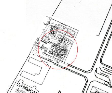
The fat preparation room and steam boiler
room are located between the main process building and the tank farm, providing
protection for most of the storage tanks from the blast wave. However, T10
(methanol storage tank) and T7 (PFAD storage tank) are directly exposed and may
be seriously damaged. Considering all the vapour cloud explosion scenarios that
can reach these tanks at an overpressure of 3 psi, the frequency of explosions
causing rupture of T10 is estimated as 2.59(10-6 per year, and the
frequency causing rupture of T7 is estimated as 1.59(10-6 per year.
These frequencies are obtained by adding up the frequencies of all the relevant
scenarios, as indicated in Table 8.6f.
Catastrophic loss of containment from T10 and T7 could lead to overtopping of
their bunds, followed by potential pool fire in the plant. These scenarios are
shown in Table 8.5i and the consequences
are detailed in Table 8.7g. Based on
the analysis carried for bund overtopping due to the failure of these tanks, no
spillage beyond the plant boundary is expected.
Table
8.6f Frequency of tank failure due
to escalation from explosion in process building
|
Equipment
involved in initial incident
|
Rupture/Leak
|
Isolation
Successful
|
Ventilation
Successful
|
Freq. of
Incident
|
Tanks
Affected
|
|
Esterification with catalyst
|
Rupture
|
N
|
Y
|
1.80E-07
|
T7, T10
|
|
Esterification with catalyst
|
Rupture
|
N
|
N
|
8.00E-08
|
T7, T10
|
|
Esterification with catalyst
|
Leak
|
N
|
N
|
2.00E-08
|
T10
|
|
Methanol buffer tank
|
Rupture
|
N
|
N
|
4.00E-08
|
T7, T10
|
|
Methanol buffer tank
|
Leak
|
N
|
N
|
1.00E-08
|
T10
|
|
Pipe reactor
|
Rupture
|
N
|
Y
|
1.26E-07
|
T10
|
|
Pipe reactor
|
Rupture
|
N
|
N
|
3.50E-08
|
T7, T10
|
|
Pipe reactor
|
Leak
|
N
|
Y
|
6.30E-07
|
T10
|
|
Pipe reactor
|
Leak
|
N
|
N
|
1.75E-07
|
T7, T10
|
|
Pipe reactor
|
Rupture
|
Y
|
N
|
1.26E-07
|
T7, T10
|
|
Pipe reactor
|
Leak
|
Y
|
N
|
6.30E-07
|
T7, T10
|
|
MEK buffer tank
|
Rupture
|
N
|
N
|
8.00E-08
|
T7, T10
|
|
MEK buffer tank
|
Leak
|
N
|
N
|
2.00E-08
|
T10
|
|
GLP collection tank
|
Rupture
|
N
|
Y
|
9.00E-08
|
T10
|
|
GLP collection tank
|
Rupture
|
N
|
N
|
4.00E-08
|
T7, T10
|
|
GLP collection tank
|
Leak
|
N
|
N
|
1.00E-08
|
T10
|
|
Acidulation tank
|
Rupture
|
N
|
N
|
4.00E-08
|
T7, T10
|
|
Acidulation tank
|
Leak
|
N
|
N
|
1.00E-08
|
T10
|
|
FFA buffer tank
|
Rupture
|
N
|
N
|
4.00E-08
|
T7, T10
|
|
FFA buffer tank
|
Leak
|
N
|
N
|
1.00E-08
|
T10
|
|
Neutralization tank
|
Rupture
|
N
|
N
|
8.00E-08
|
T7, T10
|
|
Neutralization tank
|
Leak
|
N
|
N
|
2.00E-08
|
T10
|
|
Methanol recycle tank
|
Rupture
|
N
|
N
|
4.00E-08
|
T7, T10
|
|
Methanol recycle tank
|
Leak
|
N
|
N
|
1.00E-08
|
T10
|
|
GLP settling tank
|
Rupture
|
N
|
N
|
4.00E-08
|
T10
|
|
Total frequency for rupture of T10 due to escalation
|
2.59E-06
|
|
|
Total frequency for rupture of T7 due to escalation
|
1.59E-06
|
|
8.6.6
Summary
of Scenario Outcome Frequencies
Combining
the initiating event frequency with probabilities for each branch of the event
trees gives the outcome frequency for each scenario. A complete list of these
scenarios and their frequencies is provided in Table 8.6g and Table 8.6h.
Table
8.6g Outcome Event Frequencies (Tank farm,
Marine and Transport Scenarios)
|
Section No.
|
Section Code
|
Description
|
Equipment Tag
|
Outcome Frequency (per year)
|
|
|
Leak
|
Rupture
|
|
|
Bund fire
|
Pool fire
(unconfined)
|
Flash fire
|
VCE
|
Toxic
|
Bund fire
|
Pool fire (unconfined)
|
Flash fire
|
VCE
|
Toxic
|
|
|
Tank farm
|
|
|
|
|
|
|
|
|
|
|
|
|
|
1
|
T1/T2
|
Crude
grease trap waste storage tank
|
B100300/
B100400
|
1.6(10-6
|
|
|
|
|
6.0(10-8
|
2.0(10-8
|
|
|
|
|
|
|
|
|
|
|
|
|
|
|
|
2
|
T3
|
Cleaned
grease trap waste storage tank
|
B100500
|
8.0(10-7
|
|
|
|
|
3.0(10-8
|
1.0(10-8
|
|
|
|
|
|
|
|
|
|
|
|
|
|
|
|
3
|
T4/T5
|
Crude
waste cooking oil storage tank
|
B100600/
B100700
|
1.6(10-6
|
|
|
|
|
6.0(10-8
|
2.0(10-8
|
|
|
|
|
|
|
|
|
|
|
|
|
|
|
|
4
|
T6
|
Cleaned
waste cooking oil storage tank
|
B100800
|
8.0(10-7
|
|
|
|
|
3.0(10-8
|
1.0(10-8
|
|
|
|
|
|
|
|
|
|
|
|
|
|
|
|
5
|
T7
|
PFAD
storage tank
|
B100900
|
8.0(10-7
|
|
|
|
|
3.0(10-8
|
1.0(10-8
(f)
1.59x10⁻⁶ (g)
|
|
|
|
|
|
|
|
|
|
|
|
|
|
|
|
6
|
T8
|
Crude
animal fats storage tank
|
B100100
|
8.0(10-7
|
|
|
|
|
3.0(10-8
|
1.0(10-8
|
|
|
|
|
|
|
|
|
|
|
|
|
|
|
|
7
|
T9
|
Cleaned
animal fats storage tank
|
B100200
|
8.0(10-7
|
|
|
|
|
3.0(10-8
|
1.0(10-8
|
|
|
|
|
|
|
|
|
|
|
|
|
|
|
|
8
|
T10
|
Methanol
storage tank
|
B102400
|
4.0(10-6
|
|
2.0(10-7
|
3.8(10-6
|
9.2(10-5
|
5.0(10-8
|
1.5(10-7
(f)
2.59x10⁻⁶ (g)
|
2.5(10-9
(a)
1.5(10-8
(b)
|
2.0(10-9
(a) 1.8(10-7
(b)
|
1.15(10-6
|
|
9
|
T14
|
Infineum (additive) storage tank
|
B102200
|
8.0(10-7
|
|
|
|
|
2.0(10-8
|
2.0(10-8
|
|
|
|
|
|
|
|
|
|
|
|
|
|
|
|
10
|
T15/
T16
|
Quality
biodiesel storage tank
|
B200500/
B200600
|
1.6(10-6
|
|
|
|
|
6.0(10-8
|
2.0(10-8
|
|
|
|
|
|
|
|
|
|
|
|
|
|
|
|
11
|
T17
|
Biodiesel-Europe
storage tank
|
B200700
|
8.0(10-7
|
|
|
|
|
2.0(10-8
|
2.0(10-8
|
|
|
|
|
|
|
|
|
|
|
|
|
|
|
|
12
|
T18
|
Biodiesel-Hong
Kong storage tank
|
B200800
|
8.0(10-7
|
|
|
|
|
3.0(10-8
|
1.0(10-8
|
|
|
|
|
|
|
|
|
|
|
|
|
|
|
|
13
|
T19
|
Glycerine
storage tank
|
B202100
|
8.0(10-7
|
|
|
|
|
2.0(10-8
|
2.0(10-8
|
|
|
|
|
|
|
|
|
|
|
|
|
|
|
|
14
|
T21
|
Bioheating
oil storage tank
|
B202200
|
8.0(10-7
|
|
|
|
|
3.0(10-8
|
1.0(10-8
|
|
|
|
|
|
|
|
|
|
|
|
|
|
|
|
15
|
T22
|
Gas
oil storage tank
|
B102300
|
8.0(10-7
|
|
|
|
|
3.0(10-8
|
1.0(10-8
|
|
|
|
|
|
|
|
|
|
|
|
|
|
|
|
16
|
T24
|
Crude
waste cooking oil
|
B101000
|
8.0(10-7
|
|
|
|
|
2.0(10-8
|
2.0(10-8
|
|
|
|
|
|
|
|
|
|
|
|
|
|
|
|
17
|
G01
|
Biogas
buffer tank
|
V601
|
|
|
1.0(10-4
|
|
|
|
|
5.0(10-6
|
|
|
|
|
|
|
|
|
|
|
|
|
|
|
|
|
|
|
|
|
|
|
|
|
|
Marine
scenarios
|
|
|
|
|
|
|
|
|
|
|
|
|
|
29
|
M01
|
Biodiesel/PFAD
barge
|
-
|
|
7.68(10-8
(c)
|
|
|
|
|
6.14(10-7
|
|
|
|
|
|
2.05(10-7
(d)
|
|
|
|
|
|
|
|
|
|
30
|
M02
|
Methanol
barge
|
-
|
|
|
|
|
|
|
2.04(10-6
(e)
|
|
|
|
|
|
|
|
|
|
|
|
|
|
|
|
|
|
|
|
31
|
M03
|
Methanol
ISO-tanker
|
-
|
|
7.15(10-10
|
7.15(10-10
|
|
1.42(10-7
|
|
2.28(10-9
|
2.28(10-9
|
|
5.24(10-8
|
|
|
|
|
|
|
|
|
|
|
|
|
|
|
|
|
Transport
scenarios
|
|
|
|
|
|
|
|
|
|
|
|
|
|
32
|
L01
|
Unloading
line from jetty to tanks (biodiesel/PFAD)
|
-
|
|
4.41(10-8
|
|
|
|
|
1.40(10-8
|
|
|
|
|
|
|
|
|
|
|
|
|
|
|
|
33
|
L02
|
Unloading
line from jetty to tanks (methanol)
|
|
|
3.86(10-8
|
3.86(10-8
|
|
2.49(10-6
|
|
1.22(10-8
|
1.22(10-8
|
|
2.80(10-7
|
|
|
|
|
|
|
|
|
|
|
|
|
34
|
RT1
|
Road
tanker for fats & oils
|
-
|
|
1.50(10-8
|
|
|
|
|
4.80(10-8
|
|
|
|
|
|
|
|
|
|
|
|
|
|
|
|
35
|
L03
|
Road
tanker unloading line
|
-
|
|
6.33(10-7
|
|
|
|
|
1.92(10-7
|
|
|
|
|
|
|
|
|
|
|
|
|
|
|
|
|
|
|
|
Notes:
(a) Flash
fire frequency for a vapour cloud from bund area
(b) Flash
fire frequency for vaporisation from a liquid pool that overtopped the bund
(c) Small
leaks releasing 5% of inventory within 20 minutes
(d) Large
leaks releasing 15% of inventory within 20 minutes
(e) Since
methanol is miscible with water, leakage into sea will have no effect. This
scenario is therefore modelled as a tank fire on the barge
(f) Generic
outcome frequency for rupture of tanks T7 and T10 leading to unconfined pool
fire
(g) Outcome
frequency for rupture of tanks T7 and T10 triggered by VCE inside process
building, leading to unconfined pool fire (derived from Table 8.6f)
|
|
|
|
|
|
|
|
|
|
|
|
|
|
|
|
Table 8.6h Outcome Event Frequencies (Process Area)
|
Section No.
|
Section Code
|
Description
|
Equipment Tag
|
|
Outcome Frequency (per year)
|
|
Leak
|
Rupture
|
|
Isolation failure, ventilation success
|
Isolation failure, ventilation failure
|
Isolation success, ventilation success
|
Isolation success, ventilation failure
|
Isolation failure, ventilation success
|
Isolation failure, ventilation failure
|
Isolation success, ventilation success
|
Isolation success, ventilation failure
|
|
18
|
P01
|
Esterification
with catalyst
|
B10200, B10400
|
VCE
|
9.00x10⁻⁸
|
2.00 x10⁻⁸
|
1.62 x10⁻⁷
|
9.00 x10⁻⁸
|
1.80 x10⁻⁷
|
8.00 x10⁻⁸
|
NA
|
NA
|
|
|
|
Toxic
|
1.79x10⁻⁵
|
1.98 x10⁻⁶
|
1.62 x10⁻⁴
|
1.79 x10⁻⁵
|
1.78 x10⁻⁵
|
1.92 x10⁻⁶
|
NA
|
NA
|
|
19
|
P02
|
Methanol buffer
tank
|
B111100
|
VCE
|
4.50x10⁻⁸
|
1.00 x10⁻⁸
|
8.10 x10⁻⁸
|
4.50 x10⁻⁸
|
9.00 x10⁻⁸
|
4.00 x10⁻⁸
|
NA
|
NA
|
|
|
|
|
|
Toxic
|
8.96x10⁻⁶
|
9.90 x10⁻⁷
|
8.09 x10⁻⁵
|
8.96 x10⁻⁶
|
8.91 x10⁻⁶
|
9.60 x10⁻⁷
|
NA
|
NA
|
|
20
|
P03
|
Pipe reactor
|
SP112000
|
VCE
|
6.30x10⁻⁷
|
1.75 x10⁻⁷
|
1.42 x10⁻⁶
|
6.30 x10⁻⁷
|
1.26 x10⁻⁷
|
3.50 x10⁻⁸
|
2.84 x10⁻⁷
|
1.26 x10⁻⁷
|
|
|
|
|
|
Toxic
|
1.51x10⁻⁵
|
1.58 x10⁻⁶
|
1.40 x10⁻⁴
|
1.51 x10⁻⁵
|
3.02 x10⁻⁶
|
3.15 x10⁻⁷
|
2.81 x10⁻⁵
|
3.02 x10⁻⁶
|
|
21
|
P04
|
Methanol recycle
tank
|
B72300
|
VCE
|
4.50x10⁻⁸
|
1.00 x10⁻⁸
|
8.10 x10⁻⁸
|
4.50 x10⁻⁸
|
9.00 x10⁻⁸
|
4.00 x10⁻⁸
|
NA
|
NA
|
|
|
|
|
Toxic
|
8.96x10⁻⁶
|
9.90 x10⁻⁷
|
8.09 x10⁻⁵
|
8.96 x10⁻⁶
|
8.91 x10⁻⁶
|
9.60 x10⁻⁷
|
NA
|
NA
|
|
22
|
P05
|
MEK buffer tank
|
B20500, B20600
|
VCE
|
9.00x10⁻⁸
|
2.00 x10⁻⁸
|
1.62 x10⁻⁷
|
9.00 x10⁻⁸
|
1.80 x10⁻⁷
|
8.00 x10⁻⁸
|
NA
|
NA
|
|
|
|
|
Toxic
|
1.79x10⁻⁵
|
1.98 x10⁻⁶
|
1.62 x10⁻⁴
|
1.79 x10⁻⁵
|
1.78 x10⁻⁵
|
1.92 x10⁻⁶
|
NA
|
NA
|
|
23
|
P06
|
GLP settling tank
|
B60300
|
VCE
|
4.50x10⁻⁸
|
1.00 x10⁻⁸
|
8.10 x10⁻⁸
|
4.50 x10⁻⁸
|
9.00 x10⁻⁸
|
4.00 x10⁻⁸
|
NA
|
NA
|
|
|
|
|
|
Toxic
|
8.96 x10⁻⁶
|
9.90 x10⁻⁷
|
8.09 x10⁻⁵
|
8.96 x10⁻⁶
|
8.91 x10⁻⁶
|
9.60 x10⁻⁷
|
NA
|
NA
|
|
24
|
P07
|
GLP collection
tank
|
B50100
|
VCE
|
4.50 x10⁻⁸
|
1.00 x10⁻⁸
|
8.10 x10⁻⁸
|
4.50 x10⁻⁸
|
9.00 x10⁻⁸
|
4.00 x10⁻⁸
|
NA
|
NA
|
|
|
|
|
|
Toxic
|
8.96 x10⁻⁶
|
9.90 x10⁻⁷
|
8.09 x10⁻⁵
|
8.96 x10⁻⁶
|
8.91 x10⁻⁶
|
9.60 x10⁻⁷
|
NA
|
NA
|
|
25
|
P08
|
Acidulation tank
|
B50400
|
VCE
|
4.50 x10⁻⁸
|
1.00 x10⁻⁸
|
8.10 x10⁻⁸
|
4.50 x10⁻⁸
|
9.00 x10⁻⁸
|
4.00 x10⁻⁸
|
NA
|
NA
|
|
|
|
|
|
Toxic
|
8.96 x10⁻⁶
|
9.90 x10⁻⁷
|
8.09 x10⁻⁵
|
8.96 x10⁻⁶
|
8.91 x10⁻⁶
|
9.60 x10⁻⁷
|
NA
|
NA
|
|
26
|
P09
|
FFA buffer tank
|
B50900
|
VCE
|
4.50 x10⁻⁸
|
1.00 x10⁻⁸
|
8.10 x10⁻⁸
|
4.50 x10⁻⁸
|
9.00 x10⁻⁸
|
4.00 x10⁻⁸
|
NA
|
NA
|
|
|
|
|
|
Toxic
|
8.96 x10⁻⁶
|
9.90 x10⁻⁷
|
8.09 x10⁻⁵
|
8.96 x10⁻⁶
|
8.91 x10⁻⁶
|
9.60 x10⁻⁷
|
NA
|
NA
|
|
27
|
P10
|
Neutralization
tank
|
B60100
|
VCE
|
9.00 x10⁻⁸
|
2.00 x10⁻⁸
|
1.62 x10⁻⁷
|
9.00 x10⁻⁸
|
1.80 x10⁻⁷
|
8.00 x10⁻⁸
|
NA
|
NA
|
|
|
|
|
|
Toxic
|
1.79 x10⁻⁵
|
1.98 x10⁻⁶
|
1.62 x10⁻⁴
|
1.79 x10⁻⁵
|
1.78 x10⁻⁵
|
1.92 x10⁻⁶
|
NA
|
NA
|
|
28
|
Internal explosion due to maintenance
scenario
|
|
|
|
|
|
1.08 x 10⁻⁶
(rupture frequency due to internal explosion)
|
In this study, the physical effects models
included in the PHAST v6.51 suite of models were used to assess the effects
zones for the hazardous outcomes of concern:
·
Pool
fire;
·
Flash
fire;
·
Vapour
cloud explosion in the process area; and
·
Toxic
releases of methanol.
Pool
Fires
The pool formed from a
release will initially spread due to gravitational and surface tension forces
acting on it. As the pool spreads, it will absorb heat from its surroundings and
vaporise. The pool will continue to spread until it is confined by a bund or,
for unconfined releases, until an equilibrium is reached between discharge rate
and vaporisation rate.
Bund
Overtopping
The tank farm was assessed in particular
detail in the current study. While the bund capacity is large enough to contain
spills from the storage tanks, the bund may still be overtopped due to the
dynamic effects in the case of an instantaneous failure and release of the full
contents of one of the tanks. In such a
case, if a large and full tank is located close to the bund wall and if the
release is at least partially directed towards the wall, part of the inventory
could spill over the bund wall and cause a pool fire outside the bund. The
consequences of such a release would be more severe, since the pool fire would
then cover a larger area.
The fraction of inventory that overtops
the bund was modelled using the relationship of Thyer et al ():
Q
= 0.044 — 0.264 ln (h1/H) — 0.116 ln (r1/H)
where h1 is the bund
wall height, H is the tank liquid level and r1 is the
distance from the centre of the tank to the bund wall. Applying this relation
to the storage tanks gives the calculations shown in Table 8.7a; the results are summarized in Table
8.7b. Overtopping of the site
boundary wall, at a distance of r2
from the tank centre, is also considered where there is a significant direct
path from the tank to the boundary wall, not obstructed by other tanks,
buildings or additional bund walls. The
height of the boundary wall h2 is
taken as 2m.
This modelling was done based on
experiments with water. It can be argued, however, that the higher viscosity of
biodiesel and feedstock oils used in the proposed plant would result in greatly
decreased overtopping. The grounds for this argument are as follows.
Theoretical studies by Greenspan and Young() indicate
that the extent of overtopping is related linearly to the velocity of the wave
front from the tank to the bund wall, as follows:


where H
is the tank liquid level, R is
the tank radius, T is the elapsed
time since the rupture, uw is
the mean velocity of the wave front, and cw
is the height by which the wave height exceeds the bund wall height. If it
is conservatively assumed that cw
for a viscous liquid will be equal to that for a free-flowing liquid, it can be
deduced that Q is directly
proportional to uw
Next, we consider the definition of the
dynamic viscosity, µ:

where τ
is the shear force between liquid layers in a flowing liquid, and dc/dy is the difference in velocity
between two layers separated by a depth y.
Given a constant τ, which will
be induced by the head in the tank, there is an inverse relationship between shear
velocity and viscosity. If we extrapolate from shear velocity between layers of
liquid (dc/dy) to wave front velocity
uw (i.e. the velocity
difference between the top and bottom of the flowing liquid layer), it is
reasonable to deduce an approximately inverse linear relationship between Q, the fraction of overtopping, and µ.
Typical viscosities for the combustible
liquids in the proposed plant at 40 C are as follows: water, 0.658 cP;
methanol, 0.39 cP ();
biodiesel, 3.5 cP; vegetable oil feedstock, 30 cP; Infineum, 661 cP. Thus, the
overtopping values derived from Thyer’s formula above may be adjusted by a
factor of (0.658 / 0.39) = 1.69 for methanol, (0.658 / 3.5) = 0.19 for
biodiesel, (0.658 / 30) = 0.022 for vegetable oils, and (0.658 / 661) = 0.0010
for Infineum. The adjusted values of Q
are shown in the final column of Table
8.7a. No adjustment has been applied to crude grease trap waste as this
material is around 85% water.
Table 8.7a Bund overtopping calculations
|
Tank ID
|
Description
|
Bund ID
|
Bund wall height h1 (m)
|
Maximum tank liquid level relative to
bund floor H1, H2 (m)
|
Shortest distance from centre of tank
to bund wall r1 (m)
|
Site wall height relative to bund floor
h2 (m)
|
Shortest distance from centre of tank
to site boundary r2 (m)
|
Fraction Over-topping Bund Q1
|
Fraction Over-topping Site Wall Q2
|
Fraction Reaching Outside Site Boundary
Q1(Q2
|
Q1(Q2 adjusted
for viscosity
|
|
T1
|
Crude grease trap waste storage tank
|
2A
|
3.15
|
13.8
|
7.4
|
3.5
|
30.1
|
0.51
|
0 (Obstructed)
|
0
|
0
|
|
T2
|
Crude grease trap waste storage tank
|
2A
|
3.15
|
13.8
|
7.4
|
3.5
|
17.8
|
0.51
|
0.38
|
0.19
|
0.19
|
|
T3
|
Cleaned grease trap storage tank
|
2A
|
3.15
|
13.8
|
7.4
|
3.5
|
17.8
|
0.51
|
0.38
|
0.19
|
0.004
|
|
T4
|
Crude WCO storage tank
|
2E
|
1.85
|
7.6
|
3.4
|
2.2
|
43.7
|
0.51
|
0 (Obstructed)
|
0
|
0
|
|
T5
|
Crude WCO storage tank
|
2E
|
1.85
|
7.6
|
3.4
|
2.2
|
36.3
|
0.51
|
0 (Obstructed)
|
0
|
0
|
|
T6
|
Cleaned WCO storage tank
|
2A
|
3.15
|
13.8
|
7.4
|
3.5
|
17.8
|
0.51
|
0.38
|
0.19
|
0.004
|
|
T7
|
PFAD storage tank
|
2A
|
3.15
|
13.8
|
7.4
|
3.5
|
53.6
|
0.51
|
0 (Obstructed)
|
0
|
0
|
|
T8
|
Crude animal fat storage tank
|
2A
|
3.15
|
10.9
|
7.4
|
3.5
|
17.8
|
0.42
|
0.29
|
0.12
|
0.003
|
|
T9
|
Cleaned animal fat storage tank
|
2A
|
3.15
|
10.9
|
7.4
|
3.5
|
N/A
|
0.42
|
0 (Obstructed)
|
0
|
0
|
|
T10
|
Methanol storage tank
|
2C
|
4.55
|
9.2
|
5.2
|
4.9
|
N/A
|
0.30
|
0 (Obstructed)
|
0
|
0
|
|
T14
|
Infineum (additive) storage tank
|
2F
|
1.85
|
4.7
|
3.3
|
2.2
|
13.7
|
0.33
|
0.12
|
0.04
|
0.000
|
|
T15
|
Quality biodiesel storage tank
|
2B
|
6.35
|
9.8
|
8.0
|
6.7
|
18.4
|
0.18
|
0.07
|
0.01
|
0.002
|
|
T16
|
Quality biodiesel storage tank
|
2B
|
6.35
|
9.8
|
8.0
|
6.7
|
18.4
|
0.18
|
0.07
|
0.01
|
0.002
|
|
T17
|
Biodiesel-Europe storage tank
|
2B
|
6.35
|
17.4
|
8.0
|
6.7
|
18.4
|
0.40
|
0.29
|
0.12
|
0.022
|
|
T18
|
Biodiesel-Hong Kong storage tank
|
2B
|
6.35
|
13.2
|
6.5
|
6.7
|
N/A
|
0.32
|
0 (Obstructed)
|
0
|
0
|
|
T19
|
Glycerin storage tank
|
2A
|
3.15
|
9.8
|
5.3
|
3.5
|
17.8
|
0.41
|
0.25
|
0.10
|
0.000
|
|
T21
|
Bioheating oil storage tank
|
2B
|
6.35
|
7.2
|
6.5
|
6.7
|
N/A
|
0.09
|
0 (Obstructed)
|
0
|
0
|
|
T22
|
Gas oil storage tank
|
2F
|
1.85
|
5.5
|
4.5
|
2.2
|
42.9
|
0.36
|
0 (Obstructed)
|
0
|
0
|
|
T24
|
Crude WCO storage tank
|
2B
|
6.35
|
14.7
|
7.4
|
6.7
|
18.2
|
0.35
|
0.23
|
0.08
|
0.002
|
Table
8.7b Bund Overtopping Results
|
Tank ID
|
Description
|
Q1(Q2 adjusted
for viscosity
|
Maximum inventory in tank TV (m3)
|
Spill offsite = TV (Q1(Q2 (m3)
|
Offsite Pool area (m2)
|
Offsite pool diameter (m)
|
|
T2
|
Crude grease trap waste storage tank
|
0.19
|
1420
|
269.9
|
14103
|
134
|
|
T3
|
Cleaned grease trap storage tank
|
0.004
|
965
|
3.9
|
380
|
22
|
|
T6
|
Cleaned WCO storage tank
|
0.004
|
965
|
3.9
|
380
|
22
|
|
T8
|
Crude animal fat storage tank
|
0.003
|
477
|
1.4
|
154
|
14
|
|
T15
|
Quality biodiesel storage tank
|
0.002
|
427
|
0.9
|
154
|
14
|
|
T16
|
Quality biodiesel storage tank
|
0.002
|
427
|
0.9
|
154
|
14
|
|
T17
|
Biodiesel-Europe storage tank
|
0.022
|
2111
|
46.5
|
4301
|
74
|
|
T24
|
Crude WCO storage tank
|
0.002
|
1143
|
2.3
|
254
|
18
|
The
data in Table 8.7a/b is based on the conservative assumption of the
tanks being 100% full. Lower liquid levels will produce substantially less
overtopping, according to Thyer’s formula given above. Also, it may be noted
that crude grease trap waste storage tank, which is the feedstock contains a
high proportion of water (up to 80%). Hence this liquid is not combustible.
However, this liquid has been assumed as combustible for the analysis here due
to the uncertainty in the water content and as worst case assumption.
The
modelling of leaks from storage tanks were modelled as follows:
·
Small
leaks were assumed to be contained by the bund;
·
Bund
overtopping was considered for tank rupture scenarios. The likelihood of
overtopping was estimated based on release orientation with respect to the bund
wall (see Section 8.6.4);
·
Single
overtopping of the bund was considered for all tanks. The resulting pool fire
was then modelled as an unconfined pool with contents equal to the liquid
fraction that overtopped the bund. In cases where the pool size extended beyond
the site perimeter wall, the pool size was limited by the site wall.
Essentially, it was assumed that the perimeter wall would contain these large
pools;
·
Double
overtopping of both the bund and site wall was considered only for those tanks
listed in Table 8.7b. Double overtopping is modelled as an unconfined pool
within the plant and a separate unconfined pool outside the perimeter wall,
each with their own ignition probability.
The
effects of pool fires and bund fires are modelling using the same methodology
as adopted in the PAFF EIA study ().
The flame drag distance is calculated using the Moorhouse correlation in the
HSE review ().


Fr10 = Froude number of pool fire based on
windspeed at a height of 10m.
U10 = windspeed at a height of 10m.
D’
= flame dragged diameter of pool fire (m).
D =
pool fire diameter (m).
The flame drag effects as estimated above
are considered. Where the flame drag is not significant, a minimum drag
distance of 3 m is taken, which is a conservative estimation. Any person
outdoors caught within the flame envelope is assumed to be fatally injured (ie
100% fatality). For person indoors (ie inside a building that lies within the
flame envelope considering drag), a fatality probability of 10% is assumed to
account for potential secondary fires. Anyone outside the flame envelope can
escape and hence no fatality is expected.
Geometry and
Location of Offsite Pool Fires
The
area of liquid pools offsite arising from overtopping of the site boundary wall
has been modelled using PHAST. The
equivalent circular pool diameter is calculated. The location of pools offsite
is assumed to be adjacent to the site boundary and directly opposite the source
of the spill. Examples for T2 (crude
grease trap waste) and T17 (biodiesel) are shown in Figure 8.7a.
Figure
8.7a Model of Offsite Pool Geometry
Note:
the illustration shows notional pool zones of the same area as the circular
pools modelled by PHAST.

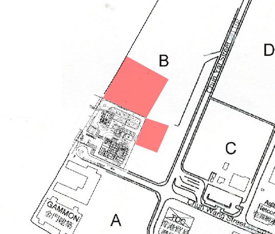

Flash
Fires
Only methanol has sufficient vapour
pressure to produce a flammable vapour cloud. For methanol releases, if there
is no immediate ignition, the vapour may disperse before subsequently
encountering an ignition source. The vapour cloud will then burn with a flash
back to the source of the leak. A flash fire is assumed to be fatal to anyone
caught within the flash fire envelope, although the short duration of a flash
fire means that radiation effects are negligible. The fatality probability is
therefore zero for persons outside the flash fire envelope. Persons indoors are
assumed to be offered some protection by the building and a fatality
probability of 0.1 is applied.
Dispersion modelling is employed by PHAST
to calculate the extent of the flammable vapour cloud. This takes into account
both the direct vaporisation from the release, and also the vapour formed from
evaporating pools. The hazard footprint was obtained by simulating the dispersion
to the lower flammability limit concentration (LFL).
The consequence modelling demonstrated
that flash fire distances are not large, extending a maximum of 45m from the
methanol storage tank and 53m from a leak in the unloading hose. These are insufficient
to affect offsite areas but are nevertheless retained in the modelling.
The possibility of a vapour cloud
dispersing from the ventilation exhaust on the roof of the process building was
also considered but consequence distances were less than 20m. If ignited, there
would be no impact at ground level and the fire would flash back to the process
building resulting in a confined vapour cloud explosion (VCE). The consequences
of the VCE are more severe than the flash fire from the vent and hence these events
were modelled as a VCE.
Vapour
Cloud Explosions
The process building is confined and
congested with process vessels. A VCE is possible if flammable concentrations
of methanol occur and is ignited. VCE in the process building is modelled using
the TNO Multi Energy explosion model included in the PHAST suite. The multi-Energy Method is a relatively simple model
to determine the blast from VCE as a function of explosion characteristic to
distance to the explosion sources and is widely used to obtain a conservative
quantification of the explosion strength. The following highlights the key
conservative assumptions of the model:
·
Based on a review of experimental data by Kineslla(), the maximum overpressure generated from an explosion
relates also to ignition energy. This is particularly true for less reactive
material such as methanol which requires a larger ignition energy to produce a
strong explosion.
·
TNO-ME also assumes that the potential explosion
source is filled with a stoichiometric fuel-air mixture and the corresponding
quantities of combustion energy is then applied for estimating the explosion
characteristic. This is a very conservative approach as it assumes the entire
energy contributing to the blast whereas only a portion of the vapour cloud
will be at the optimum stoichiometric condition in reality. Indeed, the TNO
report(2) also suggests that a gas explosion shows a gradual
development under most circumstances. Such a development implies that a portion
of the flammable mass is burned at a low combustion rate which will not
contribute to the blast of the specified high strength.
Based
on the method suggested by GAME (guidance for the application of the
multi-energy model) () ,TNO
curve 9 is used in the calculation considering the size and confinement of the
potential explosion site, obstacle size, volume blockage ratio and material
characteristic.
The
walls of the process building are metal clad. It is assumed that these will do
little to contain explosion overpressures and hence the effects of explosions
will have impact outside the building.
Process
vessels containing methanol tend to be at slightly elevated temperatures near
the boiling point of methanol. Calculations demonstrated that the vaporisation
rate upon release can be significant. The modelling took the following
approach:
·
If
emergency ventilation is successfully activated (in 90% of cases), the methanol
vapour cloud generated will be diluted and vented from the building at a rate
of minimum of 5 air changes per hour [It is noted that higher air change may be
required as per design codes, such as IP 15]. The concentration within the
building was then calculated by solving the differential equation:

where V is the volume of the
building (m3),  is the release rate of
methanol (kg/s), b is the ventilation rate (m3/s) and C
is the concentration of methanol vapour within the building (kg/m3).
This gives the concentration as a function of time and ignition is assumed to
occur at the highest concentration.
is the release rate of
methanol (kg/s), b is the ventilation rate (m3/s) and C
is the concentration of methanol vapour within the building (kg/m3).
This gives the concentration as a function of time and ignition is assumed to
occur at the highest concentration.
·
If
the emergency ventilation fails to activate, no mechanical ventilation is
assumed to continue during an incident. Also, there is assumed to be no natural
ventilation. Natural ventilation is not practicable in Ex-classified zones
(that is, zones where a flammable atmosphere may exist, requiring the use of
non-sparking electrical equipment and tools), because flammable vapours may
escape into non-flameproofed zones outside.
·
The
calculated concentration is then compared to the LEL (Lower Explosion Limit)
concentration of methanol. Ignition or explosion is not considered if the
calculated concentration is below the LFL concentration. However, it is possible that local pockets of
methanol vapour may remain at a concentration above LFL, due to uneven
ventilation. In view of this, explosion has been considered for all the
methanol release scenarios, including scenarios for which the calculated
concentration is below LEL, to account for any localized high concentration.
For these scenarios, the flammable mass is estimated based on the average
concentration inside the building, which is lower as compared to the worst case
scenario of ventilation failure
·
For
vessel ruptures, the entire contents of the vessel are assumed to be released
instantaneously. This forms a liquid pool on the floor, which then vaporises.
The pool is assumed to be confined to the process building due to the provision
of curbed areas and the vaporisation rate was determined from PHAST. All vapour
is assumed to be methanol since this is the only volatile component used in the
process building.
·
For
leaks from process vessels, the discharge rate of material is calculated based
on pressure (including head of liquid within vessel). The procedure is then
similar to that adopted for ruptures. A liquid pool is formed from which
vaporisation occurs and the transient concentration within the building is
calculated.
The fatality probability for VCEs is taken
from CIA guidelines ().
The fatality probability is higher indoors because of the increased risk from
flying debris such as breaking windows (see Table 8.7c).
Table
8.7c End Point Criteria for Vapour Cloud
Explosions
|
Overpressure (psi)
|
Fatality Probability (outdoors)
|
Fatality Probability (indoors)
|
|
5
|
0.09
|
0.55
|
|
3
|
0.02
|
0.15
|
|
1
|
0.00
|
0.01
|
Toxic
Releases
Methanol is mildly toxic and so the toxic
effects were modelled for methanol vapour clouds where ignition does not occur.
The lethal concentration in 50% of rats (LC50) is reported as
64,000ppm for a 4 hour exposure. To interpret this in terms of toxicity to
humans, the method of Lees () was
adopted. This is based on a probit equation of the form:

where Y is the probit, k1
and k2 are constants with k2 taken to be
unity, n is assumed to be 2 and t is the exposure time. For a 10
minute exposure, the LC50 concentration becomes 313,500 ppm. This is
scaled by a factor of 0.25 to convert rat dose to human dose, giving an LC50
for humans of 78,384 ppm/10min. 50% fatality occurs for a probit of 5.0. The
probit equation may therefore be solved for this boundary condition to obtain
the constant k1. This results in the following probit
equation used in the current study:

where C is in ppm and t is
in minutes. This gives the fatality probabilities summarised in Table 8.7d,
assuming 10 minute exposure.
Table
8.7d End Point Criteria for Toxic Releases
|
Methanol Concentration (ppm)
|
Fatality Probability (outdoors)
|
Fatality Probability (indoors)
|
|
190,000
|
0.99
|
0.099
|
|
113,000
|
0.9
|
0.09
|
|
59,000
|
0.5
|
0.05
|
|
31,000
|
0.1
|
0.01
|
|
18,500
|
0.01
|
0.001
|
Smoke
Dispersion
The tank farm consists of about a dozen
large storage tanks containing heavy hydrocarbons including crude vegetable
oil, biodiesel, and glycerine. In case of ignition on loss of containment, incomplete combustion of crude oil and biodiesel will
generate thick black smoke and potentially hazardous gases including carbon
monoxide, nitrogen oxides and sulphur oxides. In the case of large diameter
bund fires, a substantial volume of smoke may be produced.
However, smoke from such fire will be
buoyant and tends to rise and has minimum impact on ground level population.
This was observed in the Buncefield incident, for example (). In
the following analysis, the approach taken in the PAFF report (),
was adopted whereby the smoke plume is considered to rise at an angle
determined by the prevailing wind speed.
Based on Tseung
Kwan O meteorological data (2003-2007) (), the wind speed is 3 m/s or below for 95% of the time.
Thus, a 5 m/s wind is assumed, to assess the worst-case impact of the smoke
plume on the adjacent buildings. The results are summarized in Table 8.7e below.
In terms of existing buildings, the
closest high rise building in the vicinity is the Dream City
development in Tseung Kwan O area 86. It is about 800m north of the biodiesel
plant, so any smoke plume will be well clear of the development once it has
travelled that distance. Smoke will, therefore, pose no significant risk to the
current population of the surrounding area.
For future
developments, general buildings in the industrial estate are assumed to have a
maximum height of 30 m. Therefore, they may be affected by the smoke plume at a
distance of 10 m from the biodiesel plant boundary.
Table
8.7e Buildings adjacent to the biodiesel plant affected by
smoke plume
|
Distance of
building from the biodiesel site boundary (m)
|
Minimum height
of the building that can be affected by the smoke plume (m)
|
|
0
|
0
|
|
5
|
6
|
|
10
|
13
|
|
20
|
26
|
|
30
|
39
|
|
40
|
52
|
|
50
|
66
|
The occupants
inside the building in the vicinity of the biodiesel plant could be exposed to
potentially toxic smoke due to the combined incapacitation effects of CO2
(causing hyperventilation) and CO (toxic narcosis). The composition of smoke
plume of heavy hydrocarbons is estimated as about 11.8% CO2 and 800
ppm of CO ([57]). At 800 ppm CO, the time required for incapacitation
is about 48 seconds and at 300 ppm, the time required is 20 min.
The time between
arrival of the smoke plume and harm to the building’s occupants is estimated as
follows. The smoke could penetrate and diffuse inside the impacted building
through the heating, ventilating and air-conditioning (HVAC) system. The air
exchange rate of a typical office building is estimated as ():
( = 0.87 + 0.13 um
for an exposed site,
( = 0.88 for a
sheltered site (um < 4.2 m/s),
( = 0.22 um
for a sheltered site (um > 4.2 m/s).
Where ( is the
building air exchange rate and um is the wind speed.
To calculate the
variation of indoor concentration of toxic gases with time, it is assumed (1) the
outdoor concentration is steady and the same as the concentration in the smoke
plume, (2) any gas that penetrates the building is mixed immediately and
perfectly with all the air in the building to produce a uniform concentration.
Under these conservative assumptions, the rate of change of the indoor
concentration is simply proportional to the concentration driving force, given
by

Where Ci
is the indoor concentration (ppm), Co is the outdoor
concentration (ppm), and ( is the building air exchange rate (air
changes per hour). The indoor concentration is thus given by
Ci = C0
(1-exp(-(t))
Where t is the time elapsed since the arrival
of the smoke plume.
From this
analysis, the minimum time to reach 300 ppm CO inside the building (CO in the
smoke plume: 800 ppm) can be determined as 32 min (( > 0.87).
Considering the time required for the incapacitation at 300 ppm CO is 20 min,
there is no fatality in the first 20 min starting from the impact of the smoke
plume. Furthermore, 20 min is usually sufficient to evacuate the occupants
inside the building. Therefore, the risk of fatalities caused by the smoke
plume is assessed to be negligible. This analysis on smoke impacts is
applicable to buildings outside the flame envelope. For those buildings inside
the flame envelope, a fatality probability of 10% is assumed as described in
the earlier paragraphs under pool fire/ bund fire impacts.
Smoke from Offsite Pool Fire
Under certain
scenarios, combustible liquid (chiefly biodiesel) spilt onsite may exceed the
site boundary and possibly ignite, causing an offsite pool fire. Smoke from this fire could also affect
surrounding buildings, and this could potentially cause a greater effect than
onsite fire because the pool fire may be closer to the affected buildings.
To analyze this
situation, we have considered the duration of the worst-case offsite pool fire.
The maximum pool volume is calculated as 270 m3 (see Table 8.7a), leading to a pool area of
1.41 x 10⁴ m2, and this burns at a rate 0.039 kg s-1
m-2 ([59]) Thus, the duration of the worst pool fire is 894kg/m3
x 270 m3 / (0.039 kg s-1 m-2 x 1.41 x 104
m2) = 7.3 min. Since this is
considerably less than the 20 min required to build up a hazardous
concentration of CO indoors, the offsite pool fire can be considered to pose
negligible risk.
8.7.2
Consequence
Analysis Results
Detailed results of the consequence
analysis conducted for this risk assessment are shown in Table 8.7f, which tabulate the effect zones associated with various
end points of the hazardous outcomes considered. Consequence results are
presented in terms of:
·
d: maximum downwind distance;
·
c: maximum half-width;
·
s: offset distance between source and effect zone; and
·
m: downwind distance at which the maximum width, c, occurs.
These
dimensions (Figure 8.7b) are utilized
within the risk integration software to define the footprint area of the hazard
and calculate the number of people affected based on the meteorological data
and population distribution.
Figure
8.7b Presentation of Consequence Results
Table 8.7f Consequence
Distances
|
Section No.
|
Section Code
|
Description
|
Leak Size
|
Outcome
|
End Point Criteria
|
Weather State 1.5F
|
Weather State 3B
|
Weather State 3D
|
Weather State 6D
|
|
|
|
|
d
|
c
|
s
|
m
|
d
|
c
|
s
|
m
|
d
|
c
|
s
|
m
|
d
|
c
|
s
|
m
|
|
1
|
T1/T2
|
Crude GTW storage tank
|
Leak
|
Bund fire
|
Flame zone
|
20
|
20
|
-20
|
0
|
20
|
20
|
-20
|
0
|
20
|
20
|
-20
|
0
|
20
|
20
|
-20
|
0
|
|
F
|
|
|
|
|
Drag zone
|
23
|
23
|
-23
|
0
|
23
|
23
|
-23
|
0
|
23
|
23
|
-23
|
0
|
25
|
25
|
-25
|
0
|
|
|
|
|
Rupture
|
Bund fire
|
Flame zone
|
20
|
20
|
-20
|
0
|
20
|
20
|
-20
|
0
|
20
|
20
|
-20
|
0
|
20
|
20
|
-20
|
0
|
|
|
|
|
|
|
Drag zone
|
23
|
23
|
-23
|
0
|
23
|
23
|
-23
|
0
|
23
|
23
|
-23
|
0
|
25
|
25
|
-25
|
0
|
|
|
|
|
Rupture
|
Pool fire
|
Flame zone
|
75
|
75
|
-75
|
0
|
75
|
75
|
-75
|
0
|
75
|
75
|
-75
|
0
|
75
|
75
|
-75
|
0
|
|
|
|
|
(over- topping)
|
(unconfined)
|
Drag zone
|
78
|
78
|
-78
|
0
|
79
|
79
|
-79
|
0
|
79
|
79
|
-79
|
0
|
87
|
87
|
-87
|
0
|
|
|
|
|
Rupture
|
Pool fire
|
Flame zone
|
67
|
67
|
-67
|
0
|
67
|
67
|
-67
|
0
|
67
|
67
|
-67
|
0
|
67
|
67
|
-67
|
0
|
|
|
|
|
(over- topping)
|
(unconfined, outside site)
|
Drag zone
|
70
|
70
|
-70
|
0
|
71
|
71
|
-71
|
0
|
71
|
71
|
-71
|
0
|
78
|
78
|
-78
|
0
|
|
2
|
T3
|
Cleaned GTW storage tank
|
Leak
|
Bund fire
|
Flame zone
|
20
|
20
|
-20
|
0
|
20
|
20
|
-20
|
0
|
20
|
20
|
-20
|
0
|
20
|
20
|
-20
|
0
|
|
F
|
|
|
|
|
Drag zone
|
23
|
23
|
-23
|
0
|
23
|
23
|
-23
|
0
|
23
|
23
|
-23
|
0
|
25
|
25
|
-25
|
0
|
|
|
|
|
Rupture
|
Bund fire
|
Flame zone
|
20
|
20
|
-20
|
0
|
20
|
20
|
-20
|
0
|
20
|
20
|
-20
|
0
|
20
|
20
|
-20
|
0
|
|
|
|
|
|
|
Drag zone
|
23
|
23
|
-23
|
0
|
23
|
23
|
-23
|
0
|
23
|
23
|
-23
|
0
|
25
|
25
|
-25
|
0
|
|
|
|
|
Rupture
|
Pool fire
|
Flame zone
|
75
|
75
|
-75
|
0
|
75
|
75
|
-75
|
0
|
75
|
75
|
-75
|
0
|
75
|
75
|
-75
|
0
|
|
|
|
|
(over- topping)
|
(unconfined)
|
Drag zone
|
78
|
78
|
-78
|
0
|
79
|
79
|
-79
|
0
|
79
|
79
|
-79
|
0
|
87
|
87
|
-87
|
0
|
|
|
|
|
Rupture
|
Pool fire
|
Flame zone
|
11
|
11
|
-11
|
0
|
11
|
11
|
-11
|
0
|
11
|
11
|
-11
|
0
|
11
|
11
|
-11
|
0
|
|
|
|
|
topping)
|
(unconfined, outside site)
|
Drag zone
|
14
|
14
|
-14
|
0
|
14
|
14
|
-14
|
0
|
14
|
14
|
-14
|
0
|
15
|
15
|
-15
|
0
|
|
3
|
T4/T5
|
Crude WCO storage tank
|
Leak
|
Bund fire
|
Flame zone
|
8
|
8
|
-8
|
0
|
8
|
8
|
-8
|
0
|
8
|
8
|
-8
|
0
|
8
|
8
|
-8
|
0
|
|
F
|
|
|
|
|
Drag zone
|
11
|
11
|
-11
|
0
|
11
|
11
|
-11
|
0
|
11
|
11
|
-11
|
0
|
11
|
11
|
-11
|
0
|
|
|
|
|
Rupture
|
Bund fire
|
Flame zone
|
8
|
8
|
-8
|
0
|
8
|
8
|
-8
|
0
|
8
|
8
|
-8
|
0
|
8
|
8
|
-8
|
0
|
|
|
|
|
|
|
Drag zone
|
11
|
11
|
-11
|
0
|
11
|
11
|
-11
|
0
|
11
|
11
|
-11
|
0
|
11
|
11
|
-11
|
0
|
|
|
|
|
Rupture
|
Pool fire
|
Flame zone
|
48
|
48
|
-48
|
0
|
48
|
48
|
-48
|
0
|
48
|
48
|
-48
|
0
|
48
|
48
|
-48
|
0
|
|
|
|
|
(over-topping)
|
(unconfined)
|
Drag zone
|
51
|
51
|
-51
|
0
|
52
|
52
|
-52
|
0
|
52
|
52
|
-52
|
0
|
57
|
57
|
-57
|
0
|
|
4
|
T6
|
Cleaned WCO storage tank
|
Leak
|
Bund fire
|
Flame zone
|
20
|
20
|
-20
|
0
|
20
|
20
|
-20
|
0
|
20
|
20
|
-20
|
0
|
20
|
20
|
-20
|
0
|
|
F
|
|
|
|
|
Drag zone
|
23
|
23
|
-23
|
0
|
23
|
23
|
-23
|
0
|
23
|
23
|
-23
|
0
|
25
|
25
|
-25
|
0
|
|
|
|
|
Rupture
|
Bund fire
|
Flame zone
|
20
|
20
|
-20
|
0
|
20
|
20
|
-20
|
0
|
20
|
20
|
-20
|
0
|
20
|
20
|
-20
|
0
|
|
|
|
|
|
|
Drag zone
|
23
|
23
|
-23
|
0
|
23
|
23
|
-23
|
0
|
23
|
23
|
-23
|
0
|
25
|
25
|
-25
|
0
|
|
|
|
|
Rupture
|
Pool fire
|
Flame zone
|
75
|
75
|
-75
|
0
|
75
|
75
|
-75
|
0
|
75
|
75
|
-75
|
0
|
75
|
75
|
-75
|
0
|
|
|
|
|
(over-topping)
|
(unconfined)
|
Drag zone
|
78
|
78
|
-78
|
0
|
79
|
79
|
-79
|
0
|
79
|
79
|
-79
|
0
|
87
|
87
|
-87
|
0
|
|
|
|
|
Rupture
|
Pool fire
|
Flame zone
|
11
|
11
|
-11
|
0
|
11
|
11
|
-11
|
0
|
11
|
11
|
-11
|
0
|
11
|
11
|
-11
|
0
|
|
|
|
|
(over- topping)
|
(unconfined, outside site)
|
Drag zone
|
14
|
14
|
-14
|
0
|
14
|
14
|
-14
|
0
|
14
|
14
|
-14
|
0
|
15
|
15
|
-15
|
0
|
|
5
|
T7
|
PFAD storage tank
|
Leak
|
Bund fire
|
Flame zone
|
20
|
20
|
-20
|
0
|
20
|
20
|
-20
|
0
|
20
|
20
|
-20
|
0
|
20
|
20
|
-20
|
0
|
|
F
|
|
|
|
|
Drag zone
|
23
|
23
|
-23
|
0
|
23
|
23
|
-23
|
0
|
23
|
23
|
-23
|
0
|
25
|
25
|
-25
|
0
|
|
|
|
|
Rupture
|
Bund fire
|
Flame zone
|
20
|
20
|
-20
|
0
|
20
|
20
|
-20
|
0
|
20
|
20
|
-20
|
0
|
20
|
20
|
-20
|
0
|
|
|
|
|
|
|
Drag zone
|
23
|
23
|
-23
|
0
|
23
|
23
|
-23
|
0
|
23
|
23
|
-23
|
0
|
25
|
25
|
-25
|
0
|
|
|
|
|
Rupture
|
Pool fire
|
Flame zone
|
75
|
75
|
-75
|
0
|
75
|
75
|
-75
|
0
|
75
|
75
|
-75
|
0
|
75
|
75
|
-75
|
0
|
|
|
|
|
(over-topping)
|
(unconfined)
|
Drag zone
|
78
|
78
|
-78
|
0
|
79
|
79
|
-79
|
0
|
79
|
79
|
-79
|
0
|
87
|
87
|
-87
|
0
|
|
6
|
T8
|
Crude animal fats storage
|
Leak
|
Bund fire
|
Flame zone
|
20
|
20
|
-20
|
0
|
20
|
20
|
-20
|
0
|
20
|
20
|
-20
|
0
|
20
|
20
|
-20
|
0
|
|
F
|
|
tank
|
|
|
Drag zone
|
23
|
23
|
-23
|
0
|
23
|
23
|
-23
|
0
|
23
|
23
|
-23
|
0
|
25
|
25
|
-25
|
0
|
|
|
|
|
Rupture
|
Bund fire
|
Flame zone
|
20
|
20
|
-20
|
0
|
20
|
20
|
-20
|
0
|
20
|
20
|
-20
|
0
|
20
|
20
|
-20
|
0
|
|
|
|
|
|
|
Drag zone
|
23
|
23
|
-23
|
0
|
23
|
23
|
-23
|
0
|
23
|
23
|
-23
|
0
|
25
|
25
|
-25
|
0
|
|
|
|
|
Rupture
|
Pool fire
|
Flame zone
|
75
|
75
|
-75
|
0
|
75
|
75
|
-75
|
0
|
75
|
75
|
-75
|
0
|
75
|
75
|
-75
|
0
|
|
|
|
|
(over-topping)
|
(unconfined)
|
Drag zone
|
78
|
78
|
-78
|
0
|
79
|
79
|
-79
|
0
|
79
|
79
|
-79
|
0
|
87
|
87
|
-87
|
0
|
|
|
|
|
Rupture
|
Pool fire
|
Flame zone
|
7
|
7
|
-7
|
0
|
7
|
7
|
-7
|
0
|
7
|
7
|
-7
|
0
|
7
|
7
|
-7
|
0
|
|
|
|
|
(over-topping)
|
(unconfined, outside site)
|
Drag zone
|
10
|
10
|
-10
|
0
|
10
|
10
|
-10
|
0
|
10
|
10
|
-10
|
0
|
10
|
10
|
-10
|
0
|
|
7
|
T9
|
Clean animal fats storage
|
Leak
|
Bund fire
|
Flame zone
|
20
|
20
|
-20
|
0
|
20
|
20
|
-20
|
0
|
20
|
20
|
-20
|
0
|
20
|
20
|
-20
|
0
|
|
F
|
|
tank
|
|
|
Drag zone
|
23
|
23
|
-23
|
0
|
23
|
23
|
-23
|
0
|
23
|
23
|
-23
|
0
|
25
|
25
|
-25
|
0
|
|
|
|
|
Rupture
|
Bund fire
|
Flame zone
|
20
|
20
|
-20
|
0
|
20
|
20
|
-20
|
0
|
20
|
20
|
-20
|
0
|
20
|
20
|
-20
|
0
|
|
|
|
|
|
|
Drag zone
|
23
|
23
|
-23
|
0
|
23
|
23
|
-23
|
0
|
23
|
23
|
-23
|
0
|
25
|
25
|
-25
|
0
|
|
|
|
|
Rupture
|
Pool fire
|
Flame zone
|
75
|
75
|
-75
|
0
|
75
|
75
|
-75
|
0
|
75
|
75
|
-75
|
0
|
75
|
75
|
-75
|
0
|
|
|
|
|
(over-topping)
|
(unconfined)
|
Drag zone
|
78
|
78
|
-78
|
0
|
79
|
79
|
-79
|
0
|
79
|
79
|
-79
|
0
|
87
|
87
|
-87
|
0
|
|
8
|
T10
|
Methanol storage
|
Leak
|
Bund fire
|
Flame zone
|
7
|
7
|
-7
|
0
|
7
|
7
|
-7
|
0
|
7
|
7
|
-7
|
0
|
7
|
7
|
-7
|
0
|
|
F
|
|
tank
|
|
|
Drag zone
|
10
|
10
|
-10
|
0
|
10
|
10
|
-10
|
0
|
10
|
10
|
-10
|
0
|
10
|
10
|
-10
|
0
|
|
|
|
|
|
Flash fire
|
LFL
|
29
|
6
|
0
|
25
|
20
|
1
|
0
|
6
|
26
|
1
|
0
|
14
|
23
|
1
|
0
|
12
|
|
|
|
|
|
VCE
|
5 psi
|
0
|
0
|
0
|
0
|
0
|
0
|
0
|
0
|
0
|
0
|
0
|
0
|
0
|
0
|
0
|
0
|
|
|
|
|
|
|
3 psi
|
0
|
0
|
0
|
0
|
0
|
0
|
0
|
0
|
0
|
0
|
0
|
0
|
0
|
0
|
0
|
0
|
|
|
|
|
|
|
1 psi
|
22
|
22
|
-22
|
0
|
13
|
13
|
-13
|
0
|
14
|
14
|
-14
|
0
|
14
|
14
|
-14
|
0
|
|
|
|
|
|
Toxic release
|
190,000 ppm
|
0
|
0
|
0
|
0
|
0
|
0
|
0
|
0
|
0
|
0
|
0
|
0
|
0
|
0
|
0
|
0
|
|
|
|
|
|
|
113,000 ppm
|
13
|
1
|
0
|
5
|
12
|
1
|
0
|
5
|
12
|
1
|
0
|
5
|
12
|
1
|
0
|
5
|
|
|
|
|
|
|
59,000 ppm
|
33
|
11
|
0
|
28
|
24
|
1
|
0
|
7
|
34
|
1
|
0
|
20
|
28
|
1
|
0
|
18
|
|
|
|
|
|
|
31,000 ppm
|
43
|
24
|
0
|
33
|
37
|
2
|
0
|
8
|
58
|
3
|
0
|
40
|
42
|
3
|
0
|
28
|
|
|
|
|
|
|
18,500 ppm
|
51
|
35
|
0
|
40
|
50
|
2
|
0
|
8
|
74
|
4
|
0
|
50
|
51
|
4
|
0
|
38
|
|
|
|
|
Rupture
|
Bund fire
|
Flame zone
|
7
|
7
|
-7
|
0
|
7
|
7
|
-7
|
0
|
7
|
7
|
-7
|
0
|
7
|
7
|
-7
|
0
|
|
|
|
|
|
|
Drag zone
|
10
|
10
|
-10
|
0
|
10
|
10
|
-10
|
0
|
10
|
10
|
-10
|
0
|
10
|
10
|
-10
|
0
|
|
|
|
|
|
Flash fire
|
LFL
|
23
|
17
|
-15
|
6
|
24
|
13
|
-12
|
4
|
26
|
14
|
-13
|
4
|
36
|
11
|
-9
|
3
|
|
|
|
|
|
VCE
|
5 psi
|
0
|
0
|
0
|
0
|
0
|
0
|
0
|
0
|
0
|
0
|
0
|
0
|
0
|
0
|
0
|
0
|
|
|
|
|
|
|
3 psi
|
0
|
0
|
0
|
0
|
0
|
0
|
0
|
0
|
0
|
0
|
0
|
0
|
0
|
0
|
0
|
0
|
|
|
|
|
|
|
1 psi
|
65
|
65
|
-65
|
0
|
63
|
63
|
-63
|
0
|
65
|
65
|
-65
|
0
|
65
|
65
|
-65
|
0
|
|
|
|
|
|
Toxic release
|
190,000 ppm
|
10
|
9
|
-8
|
2
|
12
|
11
|
-10
|
2
|
12
|
11
|
-10
|
2
|
13
|
10
|
-8
|
3
|
|
|
|
|
|
|
113,000 ppm
|
14
|
11
|
-10
|
3
|
14
|
11
|
-10
|
3
|
14
|
11
|
-10
|
3
|
17
|
11
|
-9
|
3
|
|
|
|
|
|
|
59,000 ppm
|
28
|
20
|
-16
|
7
|
33
|
15
|
-14
|
5
|
33
|
16
|
-14
|
6
|
49
|
13
|
-10
|
10
|
|
|
|
|
|
|
31,000 ppm
|
43
|
31
|
-23
|
11
|
58
|
21
|
-16
|
14
|
62
|
22
|
-16
|
14
|
89
|
17
|
-13
|
25
|
|
|
|
|
|
|
18,500 ppm
|
55
|
41
|
-29
|
11
|
68
|
26
|
-19
|
25
|
81
|
27
|
-19
|
25
|
114
|
23
|
-14
|
46
|
|
|
|
|
Rupture
|
Pool fire
|
Flame zone
|
75
|
75
|
-75
|
0
|
75
|
75
|
-75
|
0
|
75
|
75
|
-75
|
0
|
75
|
75
|
-75
|
0
|
|
|
|
|
(over-topping)
|
(unconfined)
|
Drag zone
|
78
|
78
|
-78
|
0
|
79
|
79
|
-79
|
0
|
79
|
79
|
-79
|
0
|
87
|
87
|
-87
|
0
|
|
|
|
|
|
Flash fire
|
LFL
|
38
|
25
|
-16
|
12
|
32
|
14
|
-12
|
5
|
38
|
15
|
-12
|
8
|
45
|
13
|
-9
|
5
|
|
|
|
|
|
VCE
|
5 psi
|
0
|
0
|
0
|
0
|
0
|
0
|
0
|
0
|
0
|
0
|
0
|
0
|
0
|
0
|
0
|
0
|
|
|
|
|
|
|
3 psi
|
0
|
0
|
0
|
0
|
0
|
0
|
0
|
0
|
0
|
0
|
0
|
0
|
0
|
0
|
0
|
0
|
|
|
|
|
|
|
1 psi
|
85
|
85
|
-85
|
0
|
65
|
65
|
-65
|
0
|
65
|
65
|
-65
|
0
|
65
|
65
|
-65
|
0
|
|
|
|
|
|
Toxic release
|
190,000 ppm
|
11
|
10
|
-9
|
0
|
10
|
10
|
-9
|
0
|
10
|
10
|
-9
|
0
|
14
|
11
|
-9
|
3
|
|
|
|
|
|
|
113,000 ppm
|
20
|
13
|
-10
|
6
|
15
|
10
|
-10
|
2
|
17
|
12
|
-11
|
2
|
19
|
13
|
-10
|
3
|
|
|
|
|
|
|
59,000 ppm
|
45
|
30
|
-20
|
14
|
45
|
16
|
-13
|
13
|
52
|
18
|
-13
|
13
|
58
|
15
|
-11
|
11
|
|
|
|
|
|
|
31,000 ppm
|
69
|
50
|
-31
|
17
|
69
|
24
|
-17
|
33
|
81
|
28
|
-17
|
38
|
106
|
22
|
-15
|
38
|
|
|
|
|
|
|
18,500 ppm
|
186
|
67
|
-47
|
23
|
87
|
34
|
-20
|
44
|
106
|
38
|
-20
|
54
|
133
|
30
|
-17
|
85
|
|
9
|
T14
|
Infineum storage tank
|
Leak
|
Bund fire
|
Flame zone
|
6
|
6
|
-6
|
0
|
6
|
6
|
-6
|
0
|
6
|
6
|
-6
|
0
|
6
|
6
|
-6
|
0
|
|
F
|
|
|
|
|
Drag zone
|
9
|
9
|
-9
|
0
|
9
|
9
|
-9
|
0
|
9
|
9
|
-9
|
0
|
9
|
9
|
-9
|
0
|
|
|
|
|
Rupture
|
Bund fire
|
Flame zone
|
6
|
6
|
-6
|
0
|
6
|
6
|
-6
|
0
|
6
|
6
|
-6
|
0
|
6
|
6
|
-6
|
0
|
|
|
|
|
|
|
Drag zone
|
9
|
9
|
-9
|
0
|
9
|
9
|
-9
|
0
|
9
|
9
|
-9
|
0
|
9
|
9
|
-9
|
0
|
|
|
|
|
Rupture
|
Pool fire
|
Flame zone
|
60
|
60
|
-60
|
0
|
59
|
59
|
-59
|
0
|
59
|
59
|
-59
|
0
|
59
|
59
|
-59
|
0
|
|
|
|
|
(over-topping)
|
(unconfined)
|
Drag zone
|
63
|
63
|
-63
|
0
|
64
|
64
|
-64
|
0
|
64
|
64
|
-64
|
0
|
71
|
71
|
-71
|
0
|
|
10
|
T15/
|
Quality biodiesel storage
|
Leak
|
Bund fire
|
Flame zone
|
18
|
18
|
-18
|
0
|
18
|
18
|
-18
|
0
|
18
|
18
|
-18
|
0
|
18
|
18
|
-18
|
0
|
|
F
|
T16
|
tank
|
|
|
Drag zone
|
21
|
21
|
-21
|
0
|
21
|
21
|
-21
|
0
|
21
|
21
|
-21
|
0
|
23
|
23
|
-23
|
0
|
|
|
|
|
Rupture
|
Bund fire
|
Flame zone
|
18
|
18
|
-18
|
0
|
18
|
18
|
-18
|
0
|
18
|
18
|
-18
|
0
|
18
|
18
|
-18
|
0
|
|
|
|
|
|
|
Drag zone
|
21
|
21
|
-21
|
0
|
21
|
21
|
-21
|
0
|
21
|
21
|
-21
|
0
|
23
|
23
|
-23
|
0
|
|
|
|
|
Rupture
|
Pool fire
|
Flame zone
|
75
|
75
|
-75
|
0
|
75
|
75
|
-75
|
0
|
75
|
75
|
-75
|
0
|
75
|
75
|
-75
|
0
|
|
|
|
|
(over-topping)
|
(unconfined)
|
Drag zone
|
78
|
78
|
-78
|
0
|
79
|
79
|
-79
|
0
|
79
|
79
|
-79
|
0
|
87
|
87
|
-87
|
0
|
|
|
|
|
Rupture
|
Pool fire
|
Flame zone
|
7
|
7
|
-7
|
0
|
7
|
7
|
-7
|
0
|
7
|
7
|
-7
|
0
|
7
|
7
|
-7
|
0
|
|
|
|
|
(over-topping)
|
(unconfined, outside site)
|
Drag zone
|
10
|
10
|
-10
|
0
|
10
|
10
|
-10
|
0
|
10
|
10
|
-10
|
0
|
10
|
10
|
-10
|
0
|
|
11
|
T17
|
Biodiesel-Europe storage
|
Leak
|
Bund fire
|
Flame zone
|
18
|
18
|
-18
|
0
|
18
|
18
|
-18
|
0
|
18
|
18
|
-18
|
0
|
18
|
18
|
-18
|
0
|
|
F
|
|
tank
|
|
|
Drag zone
|
21
|
21
|
-21
|
0
|
21
|
21
|
-21
|
0
|
21
|
21
|
-21
|
0
|
23
|
23
|
-23
|
0
|
|
|
|
|
Rupture
|
Bund fire
|
Flame zone
|
18
|
18
|
-18
|
0
|
18
|
18
|
-18
|
0
|
18
|
18
|
-18
|
0
|
18
|
18
|
-18
|
0
|
|
|
|
|
|
|
Drag zone
|
21
|
21
|
-21
|
0
|
21
|
21
|
-21
|
0
|
21
|
21
|
-21
|
0
|
23
|
23
|
-23
|
0
|
|
|
|
|
Rupture
|
Pool fire
|
Flame zone
|
75
|
75
|
-75
|
0
|
75
|
75
|
-75
|
0
|
75
|
75
|
-75
|
0
|
75
|
75
|
-75
|
0
|
|
|
|
|
(over-topping)
|
(unconfined, inside site)
|
Drag zone
|
78
|
78
|
-78
|
0
|
79
|
79
|
-79
|
0
|
79
|
79
|
-79
|
0
|
87
|
87
|
-87
|
0
|
|
|
|
|
Rupture
|
Pool fire
|
Flame zone
|
37
|
37
|
-37
|
0
|
37
|
37
|
-37
|
0
|
37
|
37
|
-37
|
0
|
37
|
37
|
-37
|
0
|
|
|
|
|
(over-topping)
|
(unconfined, outside site)
|
Drag zone
|
40
|
40
|
-40
|
0
|
41
|
41
|
-41
|
0
|
41
|
41
|
-41
|
0
|
45
|
45
|
-45
|
0
|
|
12
|
T18
|
Biodiesel-Hong Kong
|
Leak
|
Bund fire
|
Flame zone
|
18
|
18
|
-18
|
0
|
18
|
18
|
-18
|
0
|
18
|
18
|
-18
|
0
|
18
|
18
|
-18
|
0
|
|
F
|
|
storage tank
|
|
|
Drag zone
|
21
|
21
|
-21
|
0
|
21
|
21
|
-21
|
0
|
21
|
21
|
-21
|
0
|
23
|
23
|
-23
|
0
|
|
|
|
|
Rupture
|
Bund fire
|
Flame zone
|
18
|
18
|
-18
|
0
|
18
|
18
|
-18
|
0
|
18
|
18
|
-18
|
0
|
18
|
18
|
-18
|
0
|
|
|
|
|
|
|
Drag zone
|
21
|
21
|
-21
|
0
|
21
|
21
|
-21
|
0
|
21
|
21
|
-21
|
0
|
23
|
23
|
-23
|
0
|
|
|
|
|
Rupture
|
Pool fire
|
Flame zone
|
75
|
75
|
-75
|
0
|
75
|
75
|
-75
|
0
|
75
|
75
|
-75
|
0
|
75
|
75
|
-75
|
0
|
|
|
|
|
(over-topping)
|
(unconfined)
|
Drag zone
|
78
|
78
|
-78
|
0
|
79
|
79
|
-79
|
0
|
79
|
79
|
-79
|
0
|
87
|
87
|
-87
|
0
|
|
13
|
T19
|
Glycerine storage tank
|
Leak
|
Bund fire
|
Flame zone
|
20
|
20
|
-20
|
0
|
20
|
20
|
-20
|
0
|
20
|
20
|
-20
|
0
|
20
|
20
|
-20
|
0
|
|
F
|
|
|
|
|
Drag zone
|
23
|
23
|
-23
|
0
|
23
|
23
|
-23
|
0
|
23
|
23
|
-23
|
0
|
25
|
25
|
-25
|
0
|
|
|
|
|
Rupture
|
Bund fire
|
Flame zone
|
20
|
20
|
-20
|
0
|
20
|
20
|
-20
|
0
|
20
|
20
|
-20
|
0
|
20
|
20
|
-20
|
0
|
|
|
|
|
|
|
Drag zone
|
23
|
23
|
-23
|
0
|
23
|
23
|
-23
|
0
|
23
|
23
|
-23
|
0
|
25
|
25
|
-25
|
0
|
|
|
|
|
Rupture
|
Pool fire
|
Flame zone
|
75
|
75
|
-75
|
0
|
75
|
75
|
-75
|
0
|
75
|
75
|
-75
|
0
|
75
|
75
|
-75
|
0
|
|
|
|
|
(over-topping)
|
(unconfined)
|
Drag zone
|
78
|
78
|
-78
|
0
|
79
|
79
|
-79
|
0
|
79
|
79
|
-79
|
0
|
87
|
87
|
-87
|
0
|
|
14
|
T21
|
Bioheating oil storage tank
|
Leak
|
Bund fire
|
Flame zone
|
18
|
18
|
-18
|
0
|
18
|
18
|
-18
|
0
|
18
|
18
|
-18
|
0
|
18
|
18
|
-18
|
0
|
|
F
|
|
|
|
|
Drag zone
|
21
|
21
|
-21
|
0
|
21
|
21
|
-21
|
0
|
21
|
21
|
-21
|
0
|
23
|
23
|
-23
|
0
|
|
|
|
|
Rupture
|
Bund fire
|
Flame zone
|
18
|
18
|
-18
|
0
|
18
|
18
|
-18
|
0
|
18
|
18
|
-18
|
0
|
18
|
18
|
-18
|
0
|
|
|
|
|
|
|
Drag zone
|
21
|
21
|
-21
|
0
|
21
|
21
|
-21
|
0
|
21
|
21
|
-21
|
0
|
23
|
23
|
-23
|
0
|
|
|
|
|
Rupture
|
Pool fire
|
Flame zone
|
75
|
75
|
-75
|
0
|
75
|
75
|
-75
|
0
|
75
|
75
|
-75
|
0
|
75
|
75
|
-75
|
0
|
|
|
|
|
(over-topping)
|
(unconfined)
|
Drag zone
|
78
|
78
|
-78
|
0
|
79
|
79
|
-79
|
0
|
79
|
79
|
-79
|
0
|
87
|
87
|
-87
|
0
|
|
15
|
T22
|
Gas oil storage tank
|
Leak
|
Bund fire
|
Flame zone
|
6
|
6
|
-6
|
0
|
6
|
6
|
-6
|
0
|
6
|
6
|
-6
|
0
|
6
|
6
|
-6
|
0
|
|
F
|
|
|
|
|
Drag zone
|
9
|
9
|
-9
|
0
|
9
|
9
|
-9
|
0
|
9
|
9
|
-9
|
0
|
9
|
9
|
-9
|
0
|
|
|
|
|
Rupture
|
Bund fire
|
Flame zone
|
6
|
6
|
-6
|
0
|
6
|
6
|
-6
|
0
|
6
|
6
|
-6
|
0
|
6
|
6
|
-6
|
0
|
|
|
|
|
|
|
Drag zone
|
9
|
9
|
-9
|
0
|
9
|
9
|
-9
|
0
|
9
|
9
|
-9
|
0
|
9
|
9
|
-9
|
0
|
|
|
|
|
Rupture
|
Pool fire
|
Flame zone
|
74
|
74
|
-74
|
0
|
74
|
74
|
-74
|
0
|
74
|
74
|
-74
|
0
|
74
|
74
|
-74
|
0
|
|
|
|
|
(over-topping)
|
(unconfined)
|
Drag zone
|
77
|
77
|
-77
|
0
|
78
|
78
|
-78
|
0
|
78
|
78
|
-78
|
0
|
86
|
86
|
-86
|
0
|
|
16
|
T24
|
Crude WCO storage tank
|
Leak
|
Bund fire
|
Flame zone
|
18
|
18
|
-18
|
0
|
18
|
18
|
-18
|
0
|
18
|
18
|
-18
|
0
|
18
|
18
|
-18
|
0
|
|
F
|
|
|
|
|
Drag zone
|
21
|
21
|
-21
|
0
|
21
|
21
|
-21
|
0
|
21
|
21
|
-21
|
0
|
23
|
23
|
-23
|
0
|
|
|
|
|
Rupture
|
Bund fire
|
Flame zone
|
18
|
18
|
-18
|
0
|
18
|
18
|
-18
|
0
|
18
|
18
|
-18
|
0
|
18
|
18
|
-18
|
0
|
|
|
|
|
|
|
Drag zone
|
21
|
21
|
-21
|
0
|
21
|
21
|
-21
|
0
|
21
|
21
|
-21
|
0
|
23
|
23
|
-23
|
0
|
|
|
|
|
Rupture
|
Pool fire
|
Flame zone
|
75
|
75
|
-75
|
0
|
75
|
75
|
-75
|
0
|
75
|
75
|
-75
|
0
|
75
|
75
|
-75
|
0
|
|
|
|
|
(over-topping)
|
(unconfined)
|
Drag zone
|
78
|
78
|
-78
|
0
|
79
|
79
|
-79
|
0
|
79
|
79
|
-79
|
0
|
87
|
87
|
-87
|
0
|
|
|
|
|
Rupture
|
Pool fire
|
Flame zone
|
9
|
9
|
-9
|
0
|
9
|
9
|
-9
|
0
|
9
|
9
|
-9
|
0
|
9
|
9
|
-9
|
0
|
|
|
|
|
(over-topping)
|
(unconfined, outside site)
|
Drag zone
|
12
|
12
|
-12
|
0
|
12
|
12
|
-12
|
0
|
12
|
12
|
-12
|
0
|
12
|
12
|
-12
|
0
|
|
17
|
G01
|
Biogas buffer tank
|
Rupture
|
Flash fire
|
LFL
|
3
|
3
|
-3
|
0
|
4
|
3
|
-3
|
0
|
3
|
3
|
-3
|
0
|
6
|
3
|
-3
|
0
|
|
18
|
P01
|
Esterification with catalyst
|
Rupture
|
VCE (isolation failure, ventilation success)
|
5 psi
|
51
|
51
|
-51
|
0
|
51
|
51
|
-51
|
0
|
51
|
51
|
-51
|
0
|
51
|
51
|
-51
|
0
|
|
|
|
|
|
3 psi
|
70
|
70
|
-70
|
0
|
70
|
70
|
-70
|
0
|
70
|
70
|
-70
|
0
|
70
|
70
|
-70
|
0
|
|
|
|
|
|
1 psi
|
165
|
165
|
-165
|
0
|
165
|
165
|
-165
|
0
|
165
|
165
|
-165
|
0
|
165
|
165
|
-165
|
0
|
|
|
|
|
Rupture
|
VCE (isolation failure, ventilation failure)
|
5 psi
|
57
|
57
|
-57
|
0
|
57
|
57
|
-57
|
0
|
57
|
57
|
-57
|
0
|
57
|
57
|
-57
|
0
|
|
|
|
|
|
3 psi
|
79
|
79
|
-79
|
0
|
79
|
79
|
-79
|
0
|
79
|
79
|
-79
|
0
|
79
|
79
|
-79
|
0
|
|
|
|
|
|
1 psi
|
184
|
184
|
-184
|
0
|
184
|
184
|
-184
|
0
|
184
|
184
|
-184
|
0
|
184
|
184
|
-184
|
0
|
|
|
|
|
Leak
|
VCE (isolation failure, ventilation success)
|
5 psi
|
22
|
22
|
-22
|
0
|
22
|
22
|
-22
|
0
|
22
|
22
|
-22
|
0
|
22
|
22
|
-22
|
0
|
|
|
|
|
|
3 psi
|
30
|
30
|
-30
|
0
|
30
|
30
|
-30
|
0
|
30
|
30
|
-30
|
0
|
30
|
30
|
-30
|
0
|
|
|
|
|
|
1 psi
|
72
|
72
|
-72
|
0
|
72
|
72
|
-72
|
0
|
72
|
72
|
-72
|
0
|
72
|
72
|
-72
|
0
|
|
|
|
|
|
VCE (isolation failure, ventilation failure)
|
5 psi
|
45
|
45
|
-45
|
0
|
45
|
45
|
-45
|
0
|
45
|
45
|
-45
|
0
|
45
|
45
|
-45
|
0
|
|
|
|
|
|
3 psi
|
62
|
62
|
-62
|
0
|
62
|
62
|
-62
|
0
|
62
|
62
|
-62
|
0
|
62
|
62
|
-62
|
0
|
|
|
|
|
|
1 psi
|
146
|
146
|
-146
|
0
|
146
|
146
|
-146
|
0
|
146
|
146
|
-146
|
0
|
146
|
146
|
-146
|
0
|
|
|
|
|
|
VCE (isolation success, ventilation success)
|
5 psi
|
13
|
13
|
-13
|
0
|
13
|
13
|
-13
|
0
|
13
|
13
|
-13
|
0
|
13
|
13
|
-13
|
0
|
|
|
|
|
|
3 psi
|
19
|
19
|
-19
|
0
|
19
|
19
|
-19
|
0
|
19
|
19
|
-19
|
0
|
19
|
19
|
-19
|
0
|
|
|
|
|
|
1 psi
|
44
|
44
|
-44
|
0
|
44
|
44
|
-44
|
0
|
44
|
44
|
-44
|
0
|
44
|
44
|
-44
|
0
|
|
|
|
|
|
VCE (isolation success, ventilation failure)
|
5 psi
|
25
|
25
|
-25
|
0
|
25
|
25
|
-25
|
0
|
25
|
25
|
-25
|
0
|
25
|
25
|
-25
|
0
|
|
|
|
|
|
3 psi
|
35
|
35
|
-35
|
0
|
35
|
35
|
-35
|
0
|
35
|
35
|
-35
|
0
|
35
|
35
|
-35
|
0
|
|
|
|
|
|
1 psi
|
83
|
83
|
-83
|
0
|
83
|
83
|
-83
|
0
|
83
|
83
|
-83
|
0
|
83
|
83
|
-83
|
0
|
|
19
|
P02
|
Methanol buffer tank
|
Rupture
|
VCE (isolation failure, ventilation success)
|
5 psi
|
25
|
25
|
-25
|
0
|
25
|
25
|
-25
|
0
|
25
|
25
|
-25
|
0
|
25
|
25
|
-25
|
0
|
|
|
|
|
|
3 psi
|
34
|
34
|
-34
|
0
|
34
|
34
|
-34
|
0
|
34
|
34
|
-34
|
0
|
34
|
34
|
-34
|
0
|
|
|
|
|
|
1 psi
|
80
|
80
|
-80
|
0
|
80
|
80
|
-80
|
0
|
80
|
80
|
-80
|
0
|
80
|
80
|
-80
|
0
|
|
|
|
|
|
VCE (isolation failure, ventilation failure)
|
5 psi
|
55
|
55
|
-55
|
0
|
55
|
55
|
-55
|
0
|
55
|
55
|
-55
|
0
|
55
|
55
|
-55
|
0
|
|
|
|
|
|
3 psi
|
76
|
76
|
-76
|
0
|
76
|
76
|
-76
|
0
|
76
|
76
|
-76
|
0
|
76
|
76
|
-76
|
0
|
|
|
|
|
|
1 psi
|
178
|
178
|
-178
|
0
|
178
|
178
|
-178
|
0
|
178
|
178
|
-178
|
0
|
178
|
178
|
-178
|
0
|
|
|
|
|
Leak
|
VCE (isolation failure, ventilation success)
|
5 psi
|
17
|
17
|
-17
|
0
|
17
|
17
|
-17
|
0
|
17
|
17
|
-17
|
0
|
17
|
17
|
-17
|
0
|
|
|
|
|
|
3 psi
|
24
|
24
|
-24
|
0
|
24
|
24
|
-24
|
0
|
24
|
24
|
-24
|
0
|
24
|
24
|
-24
|
0
|
|
|
|
|
|
1 psi
|
57
|
57
|
-57
|
0
|
57
|
57
|
-57
|
0
|
57
|
57
|
-57
|
0
|
57
|
57
|
-57
|
0
|
|
|
|
|
|
VCE (isolation failure, ventilation failure)
|
5 psi
|
36
|
36
|
-36
|
0
|
36
|
36
|
-36
|
0
|
36
|
36
|
-36
|
0
|
36
|
36
|
-36
|
0
|
|
|
|
|
|
3 psi
|
50
|
50
|
-50
|
0
|
50
|
50
|
-50
|
0
|
50
|
50
|
-50
|
0
|
50
|
50
|
-50
|
0
|
|
|
|
|
|
1 psi
|
118
|
118
|
-118
|
0
|
118
|
118
|
-118
|
0
|
118
|
118
|
-118
|
0
|
118
|
118
|
-118
|
0
|
|
|
|
|
|
VCE (isolation success, ventilation success)
|
5 psi
|
11
|
11
|
-11
|
0
|
11
|
11
|
-11
|
0
|
11
|
11
|
-11
|
0
|
11
|
11
|
-11
|
0
|
|
|
|
|
|
3 psi
|
16
|
16
|
-16
|
0
|
16
|
16
|
-16
|
0
|
16
|
16
|
-16
|
0
|
16
|
16
|
-16
|
0
|
|
|
|
|
|
1 psi
|
38
|
38
|
-38
|
0
|
38
|
38
|
-38
|
0
|
38
|
38
|
-38
|
0
|
38
|
38
|
-38
|
0
|
|
|
|
|
|
VCE (isolation success, ventilation failure)
|
5 psi
|
21
|
21
|
-21
|
0
|
21
|
21
|
-21
|
0
|
21
|
21
|
-21
|
0
|
21
|
21
|
-21
|
0
|
|
|
|
|
|
3 psi
|
29
|
29
|
-29
|
0
|
29
|
29
|
-29
|
0
|
29
|
29
|
-29
|
0
|
29
|
29
|
-29
|
0
|
|
|
|
|
|
1 psi
|
69
|
69
|
-69
|
0
|
69
|
69
|
-69
|
0
|
69
|
69
|
-69
|
0
|
69
|
69
|
-69
|
0
|
|
20
|
P03
|
Pipe reactor
|
Rupture
|
VCE (isolation failure, ventilation success)
|
5 psi
|
41
|
41
|
-41
|
0
|
41
|
41
|
-41
|
0
|
41
|
41
|
-41
|
0
|
41
|
41
|
-41
|
0
|
|
|
|
|
|
|
3 psi
|
57
|
57
|
-57
|
0
|
57
|
57
|
-57
|
0
|
57
|
57
|
-57
|
0
|
57
|
57
|
-57
|
0
|
|
|
|
|
|
|
1 psi
|
134
|
134
|
-134
|
0
|
134
|
134
|
-134
|
0
|
134
|
134
|
-134
|
0
|
134
|
134
|
-134
|
0
|
|
|
|
|
|
VCE (isolation failure, ventilation failure)
|
5 psi
|
57
|
57
|
-57
|
0
|
57
|
57
|
-57
|
0
|
57
|
57
|
-57
|
0
|
57
|
57
|
-57
|
0
|
|
|
|
|
|
|
3 psi
|
79
|
79
|
-79
|
0
|
79
|
79
|
-79
|
0
|
79
|
79
|
-79
|
0
|
79
|
79
|
-79
|
0
|
|
|
|
|
|
|
1 psi
|
184
|
184
|
-184
|
0
|
184
|
184
|
-184
|
0
|
184
|
184
|
-184
|
0
|
184
|
184
|
-184
|
0
|
|
|
|
|
|
VCE (isolation success, ventilation success)
|
5 psi
|
32
|
32
|
-32
|
0
|
32
|
32
|
-32
|
0
|
32
|
32
|
-32
|
0
|
32
|
32
|
-32
|
0
|
|
|
|
|
|
|
3 psi
|
45
|
45
|
-45
|
0
|
45
|
45
|
-45
|
0
|
45
|
45
|
-45
|
0
|
45
|
45
|
-45
|
0
|
|
|
|
|
|
|
1 psi
|
105
|
105
|
-105
|
0
|
105
|
105
|
-105
|
0
|
105
|
105
|
-105
|
0
|
105
|
105
|
-105
|
0
|
|
|
|
|
|
VCE (isolation success, ventilation failure)
|
5 psi
|
57
|
57
|
-57
|
0
|
57
|
57
|
-57
|
0
|
57
|
57
|
-57
|
0
|
57
|
57
|
-57
|
0
|
|
|
|
|
|
|
3 psi
|
79
|
79
|
-79
|
0
|
79
|
79
|
-79
|
0
|
79
|
79
|
-79
|
0
|
79
|
79
|
-79
|
0
|
|
|
|
|
|
|
1 psi
|
184
|
184
|
-184
|
0
|
184
|
184
|
-184
|
0
|
184
|
184
|
-184
|
0
|
184
|
184
|
-184
|
0
|
|
|
|
|
Leak
|
VCE (isolation failure, ventilation success)
|
5 psi
|
41
|
41
|
-41
|
0
|
41
|
41
|
-41
|
0
|
41
|
41
|
-41
|
0
|
41
|
41
|
-41
|
0
|
|
|
|
|
|
|
3 psi
|
57
|
57
|
-57
|
0
|
57
|
57
|
-57
|
0
|
57
|
57
|
-57
|
0
|
57
|
57
|
-57
|
0
|
|
|
|
|
|
|
1 psi
|
134
|
134
|
-134
|
0
|
134
|
134
|
-134
|
0
|
134
|
134
|
-134
|
0
|
134
|
134
|
-134
|
0
|
|
|
|
|
|
VCE (isolation failure, ventilation failure)
|
5 psi
|
57
|
57
|
-57
|
0
|
57
|
57
|
-57
|
0
|
57
|
57
|
-57
|
0
|
57
|
57
|
-57
|
0
|
|
|
|
|
|
|
3 psi
|
79
|
79
|
-79
|
0
|
79
|
79
|
-79
|
0
|
79
|
79
|
-79
|
0
|
79
|
79
|
-79
|
0
|
|
|
|
|
|
|
1 psi
|
184
|
184
|
-184
|
0
|
184
|
184
|
-184
|
0
|
184
|
184
|
-184
|
0
|
184
|
184
|
-184
|
0
|
|
|
|
|
|
VCE (isolation success, ventilation success)
|
5 psi
|
32
|
32
|
-32
|
0
|
32
|
32
|
-32
|
0
|
32
|
32
|
-32
|
0
|
32
|
32
|
-32
|
0
|
|
|
|
|
|
|
3 psi
|
45
|
45
|
-45
|
0
|
45
|
45
|
-45
|
0
|
45
|
45
|
-45
|
0
|
45
|
45
|
-45
|
0
|
|
|
|
|
|
|
1 psi
|
105
|
105
|
-105
|
0
|
105
|
105
|
-105
|
0
|
105
|
105
|
-105
|
0
|
105
|
105
|
-105
|
0
|
|
|
|
|
|
VCE (isolation success, ventilation failure)
|
5 psi
|
57
|
57
|
-57
|
0
|
57
|
57
|
-57
|
0
|
57
|
57
|
-57
|
0
|
57
|
57
|
-57
|
0
|
|
|
|
|
|
|
3 psi
|
79
|
79
|
-79
|
0
|
79
|
79
|
-79
|
0
|
79
|
79
|
-79
|
0
|
79
|
79
|
-79
|
0
|
|
|
|
|
|
|
1 psi
|
184
|
184
|
-184
|
0
|
184
|
184
|
-184
|
0
|
184
|
184
|
-184
|
0
|
184
|
184
|
-184
|
0
|
|
21
|
P04
|
Methanol recycle tank
|
Rupture
|
VCE (isolation failure, ventilation success)
|
5 psi
|
29
|
29
|
-29
|
0
|
29
|
29
|
-29
|
0
|
29
|
29
|
-29
|
0
|
29
|
29
|
-29
|
0
|
|
|
|
|
|
|
3 psi
|
40
|
40
|
-40
|
0
|
40
|
40
|
-40
|
0
|
40
|
40
|
-40
|
0
|
40
|
40
|
-40
|
0
|
|
|
|
|
|
|
1 psi
|
95
|
95
|
-95
|
0
|
95
|
95
|
-95
|
0
|
95
|
95
|
-95
|
0
|
95
|
95
|
-95
|
0
|
|
|
|
|
|
VCE (isolation failure, ventilation failure)
|
5 psi
|
57
|
57
|
-57
|
0
|
57
|
57
|
-57
|
0
|
57
|
57
|
-57
|
0
|
57
|
57
|
-57
|
0
|
|
|
|
|
|
|
3 psi
|
79
|
79
|
-79
|
0
|
79
|
79
|
-79
|
0
|
79
|
79
|
-79
|
0
|
79
|
79
|
-79
|
0
|
|
|
|
|
|
|
1 psi
|
184
|
184
|
-184
|
0
|
184
|
184
|
-184
|
0
|
184
|
184
|
-184
|
0
|
184
|
184
|
-184
|
0
|
|
|
|
|
Leak
|
VCE (isolation failure, ventilation success)
|
5 psi
|
18
|
18
|
-18
|
0
|
18
|
18
|
-18
|
0
|
18
|
18
|
-18
|
0
|
18
|
18
|
-18
|
0
|
|
|
|
|
|
|
3 psi
|
26
|
26
|
-26
|
0
|
26
|
26
|
-26
|
0
|
26
|
26
|
-26
|
0
|
26
|
26
|
-26
|
0
|
|
|
|
|
|
|
1 psi
|
61
|
61
|
-61
|
0
|
61
|
61
|
-61
|
0
|
61
|
61
|
-61
|
0
|
61
|
61
|
-61
|
0
|
|
|
|
|
|
VCE (isolation failure, ventilation failure)
|
5 psi
|
38
|
38
|
-38
|
0
|
38
|
38
|
-38
|
0
|
38
|
38
|
-38
|
0
|
38
|
38
|
-38
|
0
|
|
|
|
|
|
|
3 psi
|
53
|
53
|
-53
|
0
|
53
|
53
|
-53
|
0
|
53
|
53
|
-53
|
0
|
53
|
53
|
-53
|
0
|
|
|
|
|
|
|
1 psi
|
125
|
125
|
-125
|
0
|
125
|
125
|
-125
|
0
|
125
|
125
|
-125
|
0
|
125
|
125
|
-125
|
0
|
|
|
|
|
|
VCE (isolation success, ventilation success)
|
5 psi
|
12
|
12
|
-12
|
0
|
12
|
12
|
-12
|
0
|
12
|
12
|
-12
|
0
|
12
|
12
|
-12
|
0
|
|
|
|
|
|
|
3 psi
|
17
|
17
|
-17
|
0
|
17
|
17
|
-17
|
0
|
17
|
17
|
-17
|
0
|
17
|
17
|
-17
|
0
|
|
|
|
|
|
|
1 psi
|
40
|
40
|
-40
|
0
|
40
|
40
|
-40
|
0
|
40
|
40
|
-40
|
0
|
40
|
40
|
-40
|
0
|
|
|
|
|
|
VCE (isolation success, ventilation failure)
|
5 psi
|
22
|
22
|
-22
|
0
|
22
|
22
|
-22
|
0
|
22
|
22
|
-22
|
0
|
22
|
22
|
-22
|
0
|
|
|
|
|
|
|
3 psi
|
31
|
31
|
-31
|
0
|
31
|
31
|
-31
|
0
|
31
|
31
|
-31
|
0
|
31
|
31
|
-31
|
0
|
|
|
|
|
|
|
1 psi
|
73
|
73
|
-73
|
0
|
73
|
73
|
-73
|
0
|
73
|
73
|
-73
|
0
|
73
|
73
|
-73
|
0
|
|
22
|
P05
|
MEK buffer tank
|
Rupture
|
VCE (isolation failure, ventilation success)
|
5 psi
|
24
|
24
|
-24
|
0
|
24
|
24
|
-24
|
0
|
24
|
24
|
-24
|
0
|
24
|
24
|
-24
|
0
|
|
|
|
|
|
|
3 psi
|
33
|
33
|
-33
|
0
|
33
|
33
|
-33
|
0
|
33
|
33
|
-33
|
0
|
33
|
33
|
-33
|
0
|
|
|
|
|
|
|
1 psi
|
78
|
78
|
-78
|
0
|
78
|
78
|
-78
|
0
|
78
|
78
|
-78
|
0
|
78
|
78
|
-78
|
0
|
|
|
|
|
|
VCE (isolation failure, ventilation failure)
|
5 psi
|
53
|
53
|
-53
|
0
|
53
|
53
|
-53
|
0
|
53
|
53
|
-53
|
0
|
53
|
53
|
-53
|
0
|
|
|
|
|
|
|
3 psi
|
73
|
73
|
-73
|
0
|
73
|
73
|
-73
|
0
|
73
|
73
|
-73
|
0
|
73
|
73
|
-73
|
0
|
|
|
|
|
|
|
1 psi
|
171
|
171
|
-171
|
0
|
171
|
171
|
-171
|
0
|
171
|
171
|
-171
|
0
|
171
|
171
|
-171
|
0
|
|
|
|
|
Leak
|
VCE (isolation failure, ventilation success)
|
5 psi
|
17
|
17
|
-17
|
0
|
17
|
17
|
-17
|
0
|
17
|
17
|
-17
|
0
|
17
|
17
|
-17
|
0
|
|
|
|
|
|
|
3 psi
|
23
|
23
|
-23
|
0
|
23
|
23
|
-23
|
0
|
23
|
23
|
-23
|
0
|
23
|
23
|
-23
|
0
|
|
|
|
|
|
|
1 psi
|
55
|
55
|
-55
|
0
|
55
|
55
|
-55
|
0
|
55
|
55
|
-55
|
0
|
55
|
55
|
-55
|
0
|
|
|
|
|
|
VCE (isolation failure, ventilation failure)
|
5 psi
|
35
|
35
|
-35
|
0
|
35
|
35
|
-35
|
0
|
35
|
35
|
-35
|
0
|
35
|
35
|
-35
|
0
|
|
|
|
|
|
|
3 psi
|
49
|
49
|
-49
|
0
|
49
|
49
|
-49
|
0
|
49
|
49
|
-49
|
0
|
49
|
49
|
-49
|
0
|
|
|
|
|
|
|
1 psi
|
115
|
115
|
-115
|
0
|
115
|
115
|
-115
|
0
|
115
|
115
|
-115
|
0
|
115
|
115
|
-115
|
0
|
|
|
|
|
|
VCE (isolation success, ventilation success)
|
5 psi
|
11
|
11
|
-11
|
0
|
11
|
11
|
-11
|
0
|
11
|
11
|
-11
|
0
|
11
|
11
|
-11
|
0
|
|
|
|
|
|
|
3 psi
|
15
|
15
|
-15
|
0
|
15
|
15
|
-15
|
0
|
15
|
15
|
-15
|
0
|
15
|
15
|
-15
|
0
|
|
|
|
|
|
|
1 psi
|
35
|
35
|
-35
|
0
|
35
|
35
|
-35
|
0
|
35
|
35
|
-35
|
0
|
35
|
35
|
-35
|
0
|
|
|
|
|
|
VCE (isolation success, ventilation failure)
|
5 psi
|
21
|
21
|
-21
|
0
|
21
|
21
|
-21
|
0
|
21
|
21
|
-21
|
0
|
21
|
21
|
-21
|
0
|
|
|
|
|
|
|
3 psi
|
29
|
29
|
-29
|
0
|
29
|
29
|
-29
|
0
|
29
|
29
|
-29
|
0
|
29
|
29
|
-29
|
0
|
|
|
|
|
|
|
1 psi
|
68
|
68
|
-68
|
0
|
68
|
68
|
-68
|
0
|
68
|
68
|
-68
|
0
|
68
|
68
|
-68
|
0
|
|
23
|
P06
|
GLP settling tank
|
Rupture
|
VCE (isolation failure, ventilation success)
|
5 psi
|
21
|
21
|
-21
|
0
|
21
|
21
|
-21
|
0
|
21
|
21
|
-21
|
0
|
21
|
21
|
-21
|
0
|
|
|
|
|
|
|
3 psi
|
29
|
29
|
-29
|
0
|
29
|
29
|
-29
|
0
|
29
|
29
|
-29
|
0
|
29
|
29
|
-29
|
0
|
|
|
|
|
|
|
1 psi
|
70
|
70
|
-70
|
0
|
70
|
70
|
-70
|
0
|
70
|
70
|
-70
|
0
|
70
|
70
|
-70
|
0
|
|
|
|
|
|
VCE (isolation failure, ventilation failure)
|
5 psi
|
47
|
47
|
-47
|
0
|
47
|
47
|
-47
|
0
|
47
|
47
|
-47
|
0
|
47
|
47
|
-47
|
0
|
|
|
|
|
|
|
3 psi
|
65
|
65
|
-65
|
0
|
65
|
65
|
-65
|
0
|
65
|
65
|
-65
|
0
|
65
|
65
|
-65
|
0
|
|
|
|
|
|
|
1 psi
|
152
|
152
|
-152
|
0
|
152
|
152
|
-152
|
0
|
152
|
152
|
-152
|
0
|
152
|
152
|
-152
|
0
|
|
|
|
|
Leak
|
VCE (isolation failure, ventilation success)
|
5 psi
|
11
|
11
|
-11
|
0
|
11
|
11
|
-11
|
0
|
11
|
11
|
-11
|
0
|
11
|
11
|
-11
|
0
|
|
|
|
|
|
|
3 psi
|
16
|
16
|
-16
|
0
|
16
|
16
|
-16
|
0
|
16
|
16
|
-16
|
0
|
16
|
16
|
-16
|
0
|
|
|
|
|
|
|
1 psi
|
38
|
38
|
-38
|
0
|
38
|
38
|
-38
|
0
|
38
|
38
|
-38
|
0
|
38
|
38
|
-38
|
0
|
|
|
|
|
|
VCE (isolation failure, ventilation failure)
|
5 psi
|
25
|
25
|
-25
|
0
|
25
|
25
|
-25
|
0
|
25
|
25
|
-25
|
0
|
25
|
25
|
-25
|
0
|
|
|
|
|
|
|
3 psi
|
35
|
35
|
-35
|
0
|
35
|
35
|
-35
|
0
|
35
|
35
|
-35
|
0
|
35
|
35
|
-35
|
0
|
|
|
|
|
|
|
1 psi
|
81
|
81
|
-81
|
0
|
81
|
81
|
-81
|
0
|
81
|
81
|
-81
|
0
|
81
|
81
|
-81
|
0
|
|
|
|
|
|
VCE (isolation success, ventilation success)
|
5 psi
|
8
|
8
|
-8
|
0
|
8
|
8
|
-8
|
0
|
8
|
8
|
-8
|
0
|
8
|
8
|
-8
|
0
|
|
|
|
|
|
|
3 psi
|
12
|
12
|
-12
|
0
|
12
|
12
|
-12
|
0
|
12
|
12
|
-12
|
0
|
12
|
12
|
-12
|
0
|
|
|
|
|
|
|
1 psi
|
28
|
28
|
-28
|
0
|
28
|
28
|
-28
|
0
|
28
|
28
|
-28
|
0
|
28
|
28
|
-28
|
0
|
|
|
|
|
|
VCE (isolation success, ventilation failure)
|
5 psi
|
15
|
15
|
-15
|
0
|
15
|
15
|
-15
|
0
|
15
|
15
|
-15
|
0
|
15
|
15
|
-15
|
0
|
|
|
|
|
|
|
3 psi
|
22
|
22
|
-22
|
0
|
22
|
22
|
-22
|
0
|
22
|
22
|
-22
|
0
|
22
|
22
|
-22
|
0
|
|
|
|
|
|
|
1 psi
|
51
|
51
|
-51
|
0
|
51
|
51
|
-51
|
0
|
51
|
51
|
-51
|
0
|
51
|
51
|
-51
|
0
|
|
24
|
P07
|
GLP collection tank
|
Rupture
|
VCE (isolation failure, ventilation success)
|
5 psi
|
42
|
42
|
-42
|
0
|
42
|
42
|
-42
|
0
|
42
|
42
|
-42
|
0
|
42
|
42
|
-42
|
0
|
|
|
|
|
|
|
3 psi
|
59
|
59
|
-59
|
0
|
59
|
59
|
-59
|
0
|
59
|
59
|
-59
|
0
|
59
|
59
|
-59
|
0
|
|
|
|
|
|
|
1 psi
|
138
|
138
|
-138
|
0
|
138
|
138
|
-138
|
0
|
138
|
138
|
-138
|
0
|
138
|
138
|
-138
|
0
|
|
|
|
|
|
VCE (isolation failure, ventilation failure)
|
5 psi
|
57
|
57
|
-57
|
0
|
57
|
57
|
-57
|
0
|
57
|
57
|
-57
|
0
|
57
|
57
|
-57
|
0
|
|
|
|
|
|
|
3 psi
|
79
|
79
|
-79
|
0
|
79
|
79
|
-79
|
0
|
79
|
79
|
-79
|
0
|
79
|
79
|
-79
|
0
|
|
|
|
|
|
|
1 psi
|
184
|
184
|
-184
|
0
|
184
|
184
|
-184
|
0
|
184
|
184
|
-184
|
0
|
184
|
184
|
-184
|
0
|
|
|
|
|
Leak
|
VCE (isolation failure, ventilation success)
|
5 psi
|
19
|
19
|
-19
|
0
|
19
|
19
|
-19
|
0
|
19
|
19
|
-19
|
0
|
19
|
19
|
-19
|
0
|
|
|
|
|
|
|
3 psi
|
26
|
26
|
-26
|
0
|
26
|
26
|
-26
|
0
|
26
|
26
|
-26
|
0
|
26
|
26
|
-26
|
0
|
|
|
|
|
|
|
1 psi
|
62
|
62
|
-62
|
0
|
62
|
62
|
-62
|
0
|
62
|
62
|
-62
|
0
|
62
|
62
|
-62
|
0
|
|
|
|
|
|
VCE (isolation failure, ventilation failure)
|
5 psi
|
39
|
39
|
-39
|
0
|
39
|
39
|
-39
|
0
|
39
|
39
|
-39
|
0
|
39
|
39
|
-39
|
0
|
|
|
|
|
|
|
3 psi
|
54
|
54
|
-54
|
0
|
54
|
54
|
-54
|
0
|
54
|
54
|
-54
|
0
|
54
|
54
|
-54
|
0
|
|
|
|
|
|
|
1 psi
|
127
|
127
|
-127
|
0
|
127
|
127
|
-127
|
0
|
127
|
127
|
-127
|
0
|
127
|
127
|
-127
|
0
|
|
|
|
|
|
VCE (isolation success, ventilation success)
|
5 psi
|
12
|
12
|
-12
|
0
|
12
|
12
|
-12
|
0
|
12
|
12
|
-12
|
0
|
12
|
12
|
-12
|
0
|
|
|
|
|
|
|
3 psi
|
17
|
17
|
-17
|
0
|
17
|
17
|
-17
|
0
|
17
|
17
|
-17
|
0
|
17
|
17
|
-17
|
0
|
|
|
|
|
|
|
1 psi
|
40
|
40
|
-40
|
0
|
40
|
40
|
-40
|
0
|
40
|
40
|
-40
|
0
|
40
|
40
|
-40
|
0
|
|
|
|
|
|
VCE (isolation success, ventilation failure)
|
5 psi
|
23
|
23
|
-23
|
0
|
23
|
23
|
-23
|
0
|
23
|
23
|
-23
|
0
|
23
|
23
|
-23
|
0
|
|
|
|
|
|
|
3 psi
|
31
|
31
|
-31
|
0
|
31
|
31
|
-31
|
0
|
31
|
31
|
-31
|
0
|
31
|
31
|
-31
|
0
|
|
|
|
|
|
|
1 psi
|
74
|
74
|
-74
|
0
|
74
|
74
|
-74
|
0
|
74
|
74
|
-74
|
0
|
74
|
74
|
-74
|
0
|
|
25
|
P08
|
Acidulation tank
|
Rupture
|
VCE (isolation failure, ventilation success)
|
5 psi
|
27
|
27
|
-27
|
0
|
27
|
27
|
-27
|
0
|
27
|
27
|
-27
|
0
|
27
|
27
|
-27
|
0
|
|
|
|
|
|
|
3 psi
|
37
|
37
|
-37
|
0
|
37
|
37
|
-37
|
0
|
37
|
37
|
-37
|
0
|
37
|
37
|
-37
|
0
|
|
|
|
|
|
|
1 psi
|
88
|
88
|
-88
|
0
|
88
|
88
|
-88
|
0
|
88
|
88
|
-88
|
0
|
88
|
88
|
-88
|
0
|
|
|
|
|
|
VCE (isolation failure, ventilation failure)
|
5 psi
|
57
|
57
|
-57
|
0
|
57
|
57
|
-57
|
0
|
57
|
57
|
-57
|
0
|
57
|
57
|
-57
|
0
|
|
|
|
|
|
|
3 psi
|
79
|
79
|
-79
|
0
|
79
|
79
|
-79
|
0
|
79
|
79
|
-79
|
0
|
79
|
79
|
-79
|
0
|
|
|
|
|
|
|
1 psi
|
184
|
184
|
-184
|
0
|
184
|
184
|
-184
|
0
|
184
|
184
|
-184
|
0
|
184
|
184
|
-184
|
0
|
|
|
|
|
Leak
|
VCE (isolation failure, ventilation success)
|
5 psi
|
17
|
17
|
-17
|
0
|
17
|
17
|
-17
|
0
|
17
|
17
|
-17
|
0
|
17
|
17
|
-17
|
0
|
|
|
|
|
|
|
3 psi
|
23
|
23
|
-23
|
0
|
23
|
23
|
-23
|
0
|
23
|
23
|
-23
|
0
|
23
|
23
|
-23
|
0
|
|
|
|
|
|
|
1 psi
|
55
|
55
|
-55
|
0
|
55
|
55
|
-55
|
0
|
55
|
55
|
-55
|
0
|
55
|
55
|
-55
|
0
|
|
|
|
|
|
VCE (isolation failure, ventilation failure)
|
5 psi
|
35
|
35
|
-35
|
0
|
35
|
35
|
-35
|
0
|
35
|
35
|
-35
|
0
|
35
|
35
|
-35
|
0
|
|
|
|
|
|
|
3 psi
|
48
|
48
|
-48
|
0
|
48
|
48
|
-48
|
0
|
48
|
48
|
-48
|
0
|
48
|
48
|
-48
|
0
|
|
|
|
|
|
|
1 psi
|
113
|
113
|
-113
|
0
|
113
|
113
|
-113
|
0
|
113
|
113
|
-113
|
0
|
113
|
113
|
-113
|
0
|
|
|
|
|
|
VCE (isolation success, ventilation success)
|
5 psi
|
11
|
11
|
-11
|
0
|
11
|
11
|
-11
|
0
|
11
|
11
|
-11
|
0
|
11
|
11
|
-11
|
0
|
|
|
|
|
|
|
3 psi
|
15
|
15
|
-15
|
0
|
15
|
15
|
-15
|
0
|
15
|
15
|
-15
|
0
|
15
|
15
|
-15
|
0
|
|
|
|
|
|
|
1 psi
|
35
|
35
|
-35
|
0
|
35
|
35
|
-35
|
0
|
35
|
35
|
-35
|
0
|
35
|
35
|
-35
|
0
|
|
|
|
|
|
VCE (isolation success, ventilation failure)
|
5 psi
|
20
|
20
|
-20
|
0
|
20
|
20
|
-20
|
0
|
20
|
20
|
-20
|
0
|
20
|
20
|
-20
|
0
|
|
|
|
|
|
|
3 psi
|
28
|
28
|
-28
|
0
|
28
|
28
|
-28
|
0
|
28
|
28
|
-28
|
0
|
28
|
28
|
-28
|
0
|
|
|
|
|
|
|
1 psi
|
66
|
66
|
-66
|
0
|
66
|
66
|
-66
|
0
|
66
|
66
|
-66
|
0
|
66
|
66
|
-66
|
0
|
|
26
|
P09
|
FFA buffer tank
|
Rupture
|
VCE (isolation failure, ventilation success)
|
5 psi
|
27
|
27
|
-27
|
0
|
27
|
27
|
-27
|
0
|
27
|
27
|
-27
|
0
|
27
|
27
|
-27
|
0
|
|
|
|
|
|
|
3 psi
|
38
|
38
|
-38
|
0
|
38
|
38
|
-38
|
0
|
38
|
38
|
-38
|
0
|
38
|
38
|
-38
|
0
|
|
|
|
|
|
|
1 psi
|
89
|
89
|
-89
|
0
|
89
|
89
|
-89
|
0
|
89
|
89
|
-89
|
0
|
89
|
89
|
-89
|
0
|
|
|
|
|
|
VCE (isolation failure, ventilation failure)
|
5 psi
|
57
|
57
|
-57
|
0
|
57
|
57
|
-57
|
0
|
57
|
57
|
-57
|
0
|
57
|
57
|
-57
|
0
|
|
|
|
|
|
|
3 psi
|
79
|
79
|
-79
|
0
|
79
|
79
|
-79
|
0
|
79
|
79
|
-79
|
0
|
79
|
79
|
-79
|
0
|
|
|
|
|
|
|
1 psi
|
184
|
184
|
-184
|
0
|
184
|
184
|
-184
|
0
|
184
|
184
|
-184
|
0
|
184
|
184
|
-184
|
0
|
|
|
|
|
Leak
|
VCE (isolation failure, ventilation success)
|
5 psi
|
18
|
18
|
-18
|
0
|
18
|
18
|
-18
|
0
|
18
|
18
|
-18
|
0
|
18
|
18
|
-18
|
0
|
|
|
|
|
|
|
3 psi
|
25
|
25
|
-25
|
0
|
25
|
25
|
-25
|
0
|
25
|
25
|
-25
|
0
|
25
|
25
|
-25
|
0
|
|
|
|
|
|
|
1 psi
|
58
|
58
|
-58
|
0
|
58
|
58
|
-58
|
0
|
58
|
58
|
-58
|
0
|
58
|
58
|
-58
|
0
|
|
|
|
|
|
VCE (isolation failure, ventilation failure)
|
5 psi
|
37
|
37
|
-37
|
0
|
37
|
37
|
-37
|
0
|
37
|
37
|
-37
|
0
|
37
|
37
|
-37
|
0
|
|
|
|
|
|
|
3 psi
|
51
|
51
|
-51
|
0
|
51
|
51
|
-51
|
0
|
51
|
51
|
-51
|
0
|
51
|
51
|
-51
|
0
|
|
|
|
|
|
|
1 psi
|
119
|
119
|
-119
|
0
|
119
|
119
|
-119
|
0
|
119
|
119
|
-119
|
0
|
119
|
119
|
-119
|
0
|
|
|
|
|
|
VCE (isolation success, ventilation success)
|
5 psi
|
11
|
11
|
-11
|
0
|
11
|
11
|
-11
|
0
|
11
|
11
|
-11
|
0
|
11
|
11
|
-11
|
0
|
|
|
|
|
|
|
3 psi
|
15
|
15
|
-15
|
0
|
15
|
15
|
-15
|
0
|
15
|
15
|
-15
|
0
|
15
|
15
|
-15
|
0
|
|
|
|
|
|
|
1 psi
|
35
|
35
|
-35
|
0
|
35
|
35
|
-35
|
0
|
35
|
35
|
-35
|
0
|
35
|
35
|
-35
|
0
|
|
|
|
|
|
VCE (isolation success, ventilation failure)
|
5 psi
|
20
|
20
|
-20
|
0
|
20
|
20
|
-20
|
0
|
20
|
20
|
-20
|
0
|
20
|
20
|
-20
|
0
|
|
|
|
|
|
|
3 psi
|
28
|
28
|
-28
|
0
|
28
|
28
|
-28
|
0
|
28
|
28
|
-28
|
0
|
28
|
28
|
-28
|
0
|
|
|
|
|
|
|
1 psi
|
66
|
66
|
-66
|
0
|
66
|
66
|
-66
|
0
|
66
|
66
|
-66
|
0
|
66
|
66
|
-66
|
0
|
|
27
|
P10
|
Neutralization tank
|
Rupture
|
VCE (isolation failure, ventilation success)
|
5 psi
|
28
|
28
|
-28
|
0
|
28
|
28
|
-28
|
0
|
28
|
28
|
-28
|
0
|
28
|
28
|
-28
|
0
|
|
|
|
|
|
|
3 psi
|
39
|
39
|
-39
|
0
|
39
|
39
|
-39
|
0
|
39
|
39
|
-39
|
0
|
39
|
39
|
-39
|
0
|
|
|
|
|
|
|
1 psi
|
92
|
92
|
-92
|
0
|
92
|
92
|
-92
|
0
|
92
|
92
|
-92
|
0
|
92
|
92
|
-92
|
0
|
|
|
|
|
|
VCE (isolation failure, ventilation failure)
|
5 psi
|
57
|
57
|
-57
|
0
|
57
|
57
|
-57
|
0
|
57
|
57
|
-57
|
0
|
57
|
57
|
-57
|
0
|
|
|
|
|
|
|
3 psi
|
79
|
79
|
-79
|
0
|
79
|
79
|
-79
|
0
|
79
|
79
|
-79
|
0
|
79
|
79
|
-79
|
0
|
|
|
|
|
|
|
1 psi
|
184
|
184
|
-184
|
0
|
184
|
184
|
-184
|
0
|
184
|
184
|
-184
|
0
|
184
|
184
|
-184
|
0
|
|
|
|
|
Leak
|
VCE (isolation failure, ventilation success)
|
5 psi
|
17
|
17
|
-17
|
0
|
17
|
17
|
-17
|
0
|
17
|
17
|
-17
|
0
|
17
|
17
|
-17
|
0
|
|
|
|
|
|
|
3 psi
|
23
|
23
|
-23
|
0
|
23
|
23
|
-23
|
0
|
23
|
23
|
-23
|
0
|
23
|
23
|
-23
|
0
|
|
|
|
|
|
|
1 psi
|
55
|
55
|
-55
|
0
|
55
|
55
|
-55
|
0
|
55
|
55
|
-55
|
0
|
55
|
55
|
-55
|
0
|
|
|
|
|
|
VCE (isolation failure, ventilation failure)
|
5 psi
|
35
|
35
|
-35
|
0
|
35
|
35
|
-35
|
0
|
35
|
35
|
-35
|
0
|
35
|
35
|
-35
|
0
|
|
|
|
|
|
|
3 psi
|
49
|
49
|
-49
|
0
|
49
|
49
|
-49
|
0
|
49
|
49
|
-49
|
0
|
49
|
49
|
-49
|
0
|
|
|
|
|
|
|
1 psi
|
114
|
114
|
-114
|
0
|
114
|
114
|
-114
|
0
|
114
|
114
|
-114
|
0
|
114
|
114
|
-114
|
0
|
|
|
|
|
|
VCE (isolation success, ventilation success)
|
5 psi
|
11
|
11
|
-11
|
0
|
11
|
11
|
-11
|
0
|
11
|
11
|
-11
|
0
|
11
|
11
|
-11
|
0
|
|
|
|
|
|
|
3 psi
|
15
|
15
|
-15
|
0
|
15
|
15
|
-15
|
0
|
15
|
15
|
-15
|
0
|
15
|
15
|
-15
|
0
|
|
|
|
|
|
|
1 psi
|
35
|
35
|
-35
|
0
|
35
|
35
|
-35
|
0
|
35
|
35
|
-35
|
0
|
35
|
35
|
-35
|
0
|
|
|
|
|
|
VCE (isolation success, ventilation failure)
|
5 psi
|
20
|
20
|
-20
|
0
|
20
|
20
|
-20
|
0
|
20
|
20
|
-20
|
0
|
20
|
20
|
-20
|
0
|
|
|
|
|
|
|
3 psi
|
28
|
28
|
-28
|
0
|
28
|
28
|
-28
|
0
|
28
|
28
|
-28
|
0
|
28
|
28
|
-28
|
0
|
|
|
|
|
|
|
1 psi
|
67
|
67
|
-67
|
0
|
67
|
67
|
-67
|
0
|
67
|
67
|
-67
|
0
|
67
|
67
|
-67
|
0
|
|
29
|
M01
|
Biodiesel/PFAD barge
|
Small
|
Pool fire
|
Flame zone
|
43
|
43
|
-43
|
0
|
43
|
43
|
-43
|
0
|
43
|
43
|
-43
|
0
|
43
|
43
|
-43
|
0
|
|
|
|
|
|
(on sea)
|
Drag zone
|
46
|
46
|
-46
|
0
|
47
|
47
|
-47
|
0
|
47
|
47
|
-47
|
0
|
52
|
52
|
-52
|
0
|
|
|
|
|
Large
|
Pool fire
|
Flame zone
|
75
|
75
|
-75
|
0
|
75
|
75
|
-75
|
0
|
75
|
75
|
-75
|
0
|
75
|
75
|
-75
|
0
|
|
|
|
|
|
(on sea)
|
Drag zone
|
78
|
78
|
-78
|
0
|
79
|
79
|
-79
|
0
|
79
|
79
|
-79
|
0
|
87
|
87
|
-87
|
0
|
|
|
|
|
Rupture
|
Pool fire
|
Flame zone
|
193
|
193
|
-193
|
0
|
193
|
193
|
-193
|
0
|
193
|
193
|
-193
|
0
|
193
|
193
|
-193
|
0
|
|
|
|
|
|
(on sea)
|
Drag zone
|
196
|
196
|
-196
|
0
|
196
|
196
|
-196
|
0
|
196
|
196
|
-196
|
0
|
210
|
210
|
-210
|
0
|
|
30
|
M02
|
Methanol barge
|
Rupture
|
Tank fire
|
Flame zone
|
13
|
13
|
-13
|
0
|
13
|
13
|
-13
|
0
|
13
|
13
|
-13
|
0
|
13
|
13
|
-13
|
0
|
|
|
|
|
|
|
Drag zone
|
16
|
16
|
-16
|
0
|
16
|
16
|
-16
|
0
|
16
|
16
|
-16
|
0
|
17
|
17
|
-17
|
0
|
|
31
|
M03
|
Methanol ISO-tanker
|
Leak
|
Pool fire
|
Flame zone
|
12
|
12
|
-12
|
0
|
12
|
12
|
-12
|
0
|
12
|
12
|
-12
|
0
|
11
|
11
|
-11
|
0
|
|
|
|
|
|
|
Drag zone
|
15
|
15
|
-15
|
0
|
15
|
15
|
-15
|
0
|
15
|
15
|
-15
|
0
|
16
|
16
|
-16
|
0
|
|
|
|
|
|
Flash fire
|
LFL
|
13
|
7
|
0
|
9
|
8
|
1
|
0
|
5
|
10
|
2
|
0
|
6
|
0
|
0
|
0
|
0
|
|
|
|
|
|
Toxic release
|
190,000 ppm
|
8
|
3
|
0
|
5
|
2
|
1
|
0
|
1
|
4
|
1
|
0
|
2
|
0
|
0
|
0
|
0
|
|
|
|
|
|
|
113,000 ppm
|
10
|
5
|
0
|
7
|
6
|
1
|
0
|
3
|
7
|
1
|
0
|
4
|
0
|
0
|
0
|
0
|
|
|
|
|
|
|
59,000 ppm
|
14
|
9
|
0
|
10
|
9
|
2
|
1
|
6
|
12
|
2
|
1
|
7
|
1
|
1
|
0
|
1
|
|
|
|
|
|
|
31,000 ppm
|
19
|
13
|
0
|
12
|
12
|
2
|
0
|
9
|
15
|
3
|
0
|
11
|
3
|
1
|
0
|
2
|
|
|
|
|
|
|
18,500 ppm
|
22
|
17
|
0
|
15
|
14
|
3
|
0
|
11
|
18
|
4
|
0
|
14
|
4
|
3
|
0
|
3
|
|
|
|
|
Rupture
|
Pool fire
|
Flame zone
|
35
|
35
|
-35
|
0
|
35
|
35
|
-35
|
0
|
35
|
35
|
-35
|
0
|
35
|
35
|
-35
|
0
|
|
|
|
|
|
|
Drag zone
|
38
|
38
|
-38
|
0
|
39
|
39
|
-39
|
0
|
39
|
39
|
-39
|
0
|
43
|
43
|
-43
|
0
|
|
|
|
|
|
Flash fire
|
LFL
|
14
|
8
|
-5
|
5
|
10
|
4
|
-4
|
0
|
10
|
4
|
-4
|
0
|
11
|
4
|
-4
|
0
|
|
|
|
|
|
Toxic release
|
190,000 ppm
|
4
|
3
|
-3
|
0
|
4
|
3
|
-3
|
0
|
4
|
3
|
-3
|
0
|
4
|
3
|
-3
|
0
|
|
|
|
|
|
|
113,000 ppm
|
5
|
4
|
-4
|
0
|
5
|
4
|
-4
|
0
|
5
|
4
|
-4
|
0
|
5
|
4
|
-4
|
0
|
|
|
|
|
|
|
59,000 ppm
|
17
|
10
|
-7
|
5
|
14
|
5
|
-5
|
2
|
14
|
5
|
-5
|
2
|
18
|
5
|
-5
|
2
|
|
|
|
|
|
|
31,000 ppm
|
25
|
18
|
-10
|
8
|
30
|
8
|
-6
|
10
|
30
|
9
|
-6
|
10
|
34
|
7
|
-6
|
12
|
|
|
|
|
|
|
18,500 ppm
|
35
|
23
|
-15
|
10
|
38
|
12
|
-7
|
22
|
38
|
14
|
-7
|
22
|
43
|
10
|
-7
|
25
|
|
32
|
L01
|
Unloading hose/line from
|
Leak
|
Pool fire
|
Flame zone
|
75
|
75
|
-75
|
0
|
75
|
75
|
-75
|
0
|
75
|
75
|
-75
|
0
|
75
|
75
|
-75
|
0
|
|
|
|
jetty (biodiesel/PFAD)
|
|
(on sea)
|
Drag zone
|
78
|
78
|
-78
|
0
|
79
|
79
|
-79
|
0
|
79
|
79
|
-79
|
0
|
87
|
87
|
-87
|
0
|
|
|
|
|
Rupture
|
Pool fire
|
Flame zone
|
75
|
75
|
-75
|
0
|
75
|
75
|
-75
|
0
|
75
|
75
|
-75
|
0
|
75
|
75
|
-75
|
0
|
|
|
|
|
|
(on sea)
|
Drag zone
|
78
|
78
|
-78
|
0
|
79
|
79
|
-79
|
0
|
79
|
79
|
-79
|
0
|
87
|
87
|
-87
|
0
|
|
33
|
L02
|
Unloading hose/line from
|
Leak
|
Pool fire
|
Flame zone
|
75
|
75
|
-75
|
0
|
75
|
75
|
-75
|
0
|
75
|
75
|
-75
|
0
|
75
|
75
|
-75
|
0
|
|
|
|
jetty (methanol)
|
|
(on sea)
|
Drag zone
|
78
|
78
|
-78
|
0
|
79
|
79
|
-79
|
0
|
79
|
79
|
-79
|
0
|
87
|
87
|
-87
|
0
|
|
|
|
|
|
Flash fire
|
LFL
|
47
|
26
|
5
|
31
|
19
|
18
|
5
|
14
|
21
|
21
|
5
|
14
|
18
|
11
|
5
|
15
|
|
|
|
|
|
Toxic release
|
190,000 ppm
|
9
|
1
|
6
|
8
|
9
|
1
|
6
|
8
|
9
|
1
|
6
|
8
|
9
|
1
|
6
|
8
|
|
|
|
|
|
|
113,000 ppm
|
15
|
10
|
5
|
10
|
9
|
1
|
6
|
8
|
9
|
1
|
6
|
8
|
9
|
1
|
6
|
8
|
|
|
|
|
|
|
59,000 ppm
|
58
|
40
|
5
|
40
|
23
|
23
|
5
|
14
|
26
|
26
|
5
|
14
|
22
|
20
|
5
|
15
|
|
|
|
|
|
|
31,000 ppm
|
84
|
80
|
5
|
57
|
41
|
38
|
5
|
14
|
47
|
40
|
5
|
15
|
37
|
32
|
5
|
15
|
|
|
|
|
|
|
18,500 ppm
|
105
|
111
|
5
|
74
|
51
|
46
|
5
|
14
|
63
|
48
|
5
|
13
|
48
|
40
|
5
|
15
|
|
|
|
|
Rupture
|
Pool fire
|
Flame zone
|
75
|
75
|
-75
|
0
|
75
|
75
|
-75
|
0
|
75
|
75
|
-75
|
0
|
75
|
75
|
-75
|
0
|
|
|
|
|
|
(on sea)
|
Drag zone
|
78
|
78
|
-78
|
0
|
79
|
79
|
-79
|
0
|
79
|
79
|
-79
|
0
|
87
|
87
|
-87
|
0
|
|
|
|
|
|
Flash fire
|
LFL
|
53
|
20
|
5
|
15
|
24
|
16
|
5
|
16
|
27
|
17
|
5
|
16
|
24
|
13
|
5
|
18
|
|
|
|
|
|
Toxic release
|
190,000 ppm
|
12
|
1
|
6
|
10
|
12
|
1
|
6
|
10
|
12
|
1
|
6
|
10
|
12
|
1
|
6
|
10
|
|
|
|
|
|
|
113,000 ppm
|
17
|
9
|
5
|
12
|
12
|
1
|
5
|
10
|
12
|
1
|
5
|
10
|
12
|
1
|
5
|
10
|
|
|
|
|
|
|
59,000 ppm
|
70
|
28
|
5
|
49
|
31
|
21
|
5
|
16
|
33
|
22
|
5
|
16
|
31
|
18
|
5
|
18
|
|
|
|
|
|
|
31,000 ppm
|
102
|
66
|
5
|
75
|
56
|
33
|
5
|
16
|
63
|
33
|
5
|
16
|
55
|
29
|
5
|
17
|
|
|
|
|
|
|
18,500 ppm
|
128
|
100
|
5
|
93
|
78
|
40
|
5
|
15
|
85
|
40
|
5
|
15
|
70
|
35
|
5
|
17
|
|
34
|
RT1
|
Road tanker for fats & oils
|
Leak
|
Pool fire
|
Flame zone
|
21
|
21
|
-21
|
0
|
21
|
21
|
-21
|
0
|
21
|
21
|
-21
|
0
|
21
|
21
|
-21
|
0
|
|
|
|
|
|
|
Drag zone
|
24
|
24
|
-24
|
0
|
24
|
24
|
-24
|
0
|
24
|
24
|
-24
|
0
|
27
|
27
|
-27
|
0
|
|
|
|
|
Rupture
|
Pool fire
|
Flame zone
|
24
|
24
|
-24
|
0
|
24
|
24
|
-24
|
0
|
24
|
24
|
-24
|
0
|
24
|
24
|
-24
|
0
|
|
|
|
|
|
|
Drag zone
|
27
|
27
|
-27
|
0
|
27
|
27
|
-27
|
0
|
27
|
27
|
-27
|
0
|
30
|
30
|
-30
|
0
|
|
35
|
L03
|
Road tanker unloading line
|
Leak
|
Pool fire
|
Flame zone
|
39
|
39
|
-39
|
0
|
39
|
39
|
-39
|
0
|
39
|
39
|
-39
|
0
|
39
|
39
|
-39
|
0
|
|
|
|
|
|
|
Drag zone
|
42
|
42
|
-42
|
0
|
43
|
43
|
-43
|
0
|
43
|
43
|
-43
|
0
|
47
|
47
|
-47
|
0
|
|
|
|
|
Rupture
|
Pool fire
|
Flame zone
|
39
|
39
|
-39
|
0
|
39
|
39
|
-39
|
0
|
39
|
39
|
-39
|
0
|
39
|
39
|
-39
|
0
|
|
|
|
|
|
|
Drag zone
|
42
|
42
|
-42
|
0
|
43
|
43
|
-43
|
0
|
43
|
43
|
-43
|
0
|
47
|
47
|
-47
|
0
|
|
|
|
|
|
|
|
|
|
|
|
|
|
|
|
|
|
|
|
|
|
|
|
|
|
|
|
|
|
|
|
|
|
|
|
|
|
|
|
|
|
|
|
|
|
|
This section presents the risk results
which are derived by combining the frequency of hazardous outcome events with
the associated consequences. This is known as Risk Summation and was conducted
using in-house software RISKPLOTTM.
Societal
Risks
The overall
off-site Potential Loss of Life (PLL) value from the biodiesel plant was
estimated as 6.83x10⁻⁷ per year for the existing population, increasing to 1.59x10⁻⁵
per year with the future population, once the industrial estate is fully
developed. The main contributors to the societal risks are summarised in Table
8.8a and Table 8.8b.
Vapour cloud explosions within the process building are the main contributors
to the societal risk. Pool fires from tank leaks and unloading activities also
make some contribution. The toxic effects of methanol are minimal and do not
make significant contributions to the risks. Similarly, flash fires are only
small contributors to the overall risk because of small dispersion distances.
Table 8.8a Main
Contributors to Potential Loss of Life (PLL)
Current Population Scenario
|
Scenario
|
Scenario
Description
|
Main Hazardous
Chemical
|
PLL (per year)
|
%
|
|
P03 Pipe reactor
|
Leak leading to VCE (isolation success,
ventilation failure)
|
Methanol
|
1.64 x10⁻⁷
|
24.0%
|
|
P03 Pipe reactor
|
Leak leading to VCE (isolation failure,
ventilation success)
|
Methanol
|
7.59 x10⁻⁸
|
11.1%
|
|
P03 Pipe reactor
|
Leak leading to VCE (isolation success,
ventilation success)
|
Methanol
|
5.99 x10⁻⁸
|
8.8%
|
|
P03 Pipe reactor
|
Leak leading to VCE (isolation failure,
ventilation failure)
|
Methanol
|
4.55 x10⁻⁸
|
6.7%
|
|
M01 biodiesel/PFAD barge
|
Rupture leading to pool fire
|
Biodiesel
|
3.67 x10⁻⁸
|
5.4%
|
|
P01 Esterification reactor with catalyst
|
Rupture leading to VCE (isolation failure,
ventilation success)
|
Methanol
|
3.57 x10⁻⁸
|
5.2%
|
|
P03 Pipe reactor
|
Rupture leading to VCE (isolation success,
ventilation failure)
|
Methanol
|
3.27 x10⁻⁸
|
4.8%
|
|
T10 Methanol tank, T7 PFAD storage tank
|
Tank rupture leading to pool fire with
overtopping (VCE escalation)
|
Methanol, PFAD
|
2.35 x10⁻⁸
|
3.4%
|
|
P01 Esterification reactor
|
Rupture leading to VCE (isolation failure,
ventilation failure)
|
Methanol
|
2.08 x10⁻⁸
|
3.0%
|
|
P10 Neutralization tank
|
P10 rupture leading to VCE (isolation failure,
ventilation failure)
|
Methanol
|
2.08 x10⁻⁸
|
3.0%
|
|
Total (including
all scenarios)
|
|
|
6.83 x10⁻⁷
|
100%
|
Future Population Scenario
|
Scenario
|
Scenario Description
|
Main Hazardous Chemical
|
PLL (per year)
|
%
|
|
P03 Pipe reactor
|
Leak leading to VCE (isolation success, ventilation failure)
|
Methanol
|
2.97 x10⁻⁶
|
18.7%
|
|
Maintenance error
|
Internal explosion in process building
|
Methanol
|
2.16 x10⁻⁶ (a)
|
13.6%
|
|
T10 Methanol tank, T7 PFAD storage tank
|
Tank rupture leading to pool fire with overtopping (VCE escalation)
|
Methanol, PFAD
|
1.71 x10⁻⁶
|
10.8%
|
|
T10 Methanol storage tank
|
Rupture leading to pool fire with overtopping (VCE escalation)
|
Methanol
|
1.08 x10⁻⁶
|
6.8%
|
|
P03 Pipe reactor
|
Leak leading to VCE (isolation failure, ventilation failure)
|
Methanol
|
8.25 x10⁻⁷
|
5.2%
|
|
P03 Pipe reactor
|
Leak leading to VCE (isolation failure, ventilation success)
|
Methanol
|
8.18 x10⁻⁷
|
5.1%
|
|
P03 Pipe reactor
|
Leak leading to VCE (isolation success, ventilation success)
|
Methanol
|
5.98 x10⁻⁷
|
3.8%
|
|
P03 Pipe reactor
|
Rupture leading to VCE (isolation success, ventilation failure)
|
Methanol
|
5.94 x10⁻⁷
|
3.7%
|
|
P01 Esterification reactor with catalyst
|
Rupture leading to VCE (isolation failure, ventilation success)
|
Methanol
|
5.47 x10⁻⁷
|
3.4%
|
|
P01 Esterification reactor with catalyst
|
Rupture leading to VCE (isolation failure, ventilation failure)
|
Methanol
|
3.77 x10⁻⁷
|
2.4%
|
|
Total (including all scenarios)
|
|
|
1.59x10⁻⁵
|
100%
|
|
Note:
(a) This figure is double the frequency value derived from the
event tree in Figure 8.6l because
two fatalities have been assumed (see Page 46).
|
Table 8.8b PLL
Breakdown by Systems (Future Population)
|
System
|
PLL (per year)
|
%
|
|
Process
|
1.14 x 10⁻⁵
|
72%
|
|
Tank Farm
|
3.59 x 10⁻⁶
|
22%
|
|
Transport
|
8.76 x 10⁻⁷
|
6%
|
|
Total
|
1.59 x 10⁻⁵
|
100%
|
The FN curve
for current population and future population are presented and compared with
the Hong Kong Risk Guidelines in Figure
8.8a and Figure 8.8b.
For the
current population scenario, there is only one office building of Gammon with a
population of about 50 that lies within the consequence zone of 1 psi. This
results in fractional fatalities as the fatality probability is 1% of persons
indoor within the 1psi zone. For the current population scenario, the marine
population is also affected by pool fire events from loading/ unloading operations.
This scenario also results in fractional fatalities as the population is
distributed over an area in Junk
Bay. These outcomes with
fractional fatalities have been included in the PLL estimation. These scenarios
have also been represented in the FN curve by converting the PLL into an
equivalent frequency of one fatality and the same is shown on the FN curve in Figure 8.8a.
Considering
the potential future development in the vicinity of this plant (although of
industrial in nature), the FN curve for future case is higher than the current
case. Also, the predicted fatality range is wider.
The risks
for both current and future population case lie within the acceptable region of
the Hong Kong Risk Guidelines.
Figure
8.8a FN Curves for Current and Future Population
and their Comparison with the HK Societal Risk Guidelines
Figure 8.8b FN
Curves of Future Population and their Comparison with the HK Societal Risk
Guidelines (Breakdown by Operational Areas)
Individual Risk
The
individual risk contours for the biodiesel plant are shown in Figure
8.8c. These contours express
the risk to a hypothetical individual present outdoors 100% of the time. As
seen from the figure, the 10-5 per year contour does not extend
beyond plant boundary. Individual risk from the plant is therefore considered
acceptably low and complies with the Hong Kong
individual risk guidelines which state that the individual risk off-site should
not exceed 10-5 per year.
Figure 8.8c Individual
Risk Contours for Biodiesel Plant
 10-5 per year 10-5 per year
 10-6
per year 10-6
per year
|
Cumulative Risk
The risks
presented in Figure 8.8c represent
the risks due to the biodiesel facility. The neighbouring Hong Kong Oxygen
facility, some 400m away, also contains hazardous equipment and storage of
compressed gases that may add to the risks from the biodiesel facility.
Although no details of the Hong Kong Oxygen facility are available, it is
expected that the main risks will originate from the storage of a large number
of compressed gas cylinders. Consequence distances associated with such
equipment have a very limited range because the inventory within each cylinder
is small. Hence it may be expected that the risks will decrease rapidly with
distance from the facility. The risk levels at the biodiesel facility, being
400m away, will be negligible. The scenario of projectiles from the Hong Kong
Oxygen facility was addressed in this QRA and found to present insignificant
incremental risks to the biodiesel facility.
Similarly,
as seen from Figure 8.8c,
the risk of hazards from the proposed biodiesel plant impacting on the Hong
Kong Oxygen facility is insignificant. The risks decrease quickly offsite.
The following assumptions have been made
in the base case analysis and hence these will require taking forward during
the design and operations and need confirming:
·
The
process plant building will be provided with adequate number of gas detectors
distributed over the various areas of potential leak sources to provide
adequate coverage. A coverage factor of 90% for 1 out of N detectors for alarm to be ensured (i.e. the system will be
designed so that at least one detector (out of the N detectors provided) triggers in 90% of occasions when a high
concentration of flammables is present).
·
Additional
leak detection systems based on process parameters will be considered such as
low pressure or others as applicable.
·
Upon
gas detection, the process system will be isolated. All pumps, motors will be
stopped. Also, emergency shutdown valves will be provided at the liquid outlet
connections of major equipments holding significant inventory of methanol
(>5m3). Emergency shutdown system to meet a performance target of 90% for
the reliability of the overall shutdown system
·
Emergency
ventilation system will be provided in accordance with relevant design codes
for adequate ventilation of process areas inside buildings, to ensure that the
ventilation rate is sufficient to bring down the concentration to 50% of lower
explosive limit (LEL). Also, the ventilation system will be designed to avoid
any stagnant pockets. Relevant codes include IP 15 : Area Classification Code
for Installations Handling Flammable Liquids, IEC 60079, Part 10 :2002
Electrical Apparatus for Explosive Gas Atmospheres and NFPA 30 : The Flammable
and Combustible Liquids Code. A performance target of 90% for the reliability
of the ventilation system is to be achieved
·
All
electrical equipment inside the building will be classified in accordance with
the electrical area classification requirements. No unclassified electrical
equipment will be used during operations or maintenance.
·
Reference
will also be made to codes of practice and guidance issued in Europe
that apply
to places where explosive atmospheres may occur (called ‘ATEX’ requirements).
These are covered as part of the
European
Directive: the Explosive Atmospheres Directive (99/92/EC) and the UK
regulations, Dangerous
Substances and Explosive Atmospheres Regulations 2002 (DSEAR). Where potentially explosive
atmospheres may occur in the workplace, the requirements include, identifying and classifying (zoning) areas where potentially explosive
atmospheres may occur; avoiding ignition sources in zoned areas, in particular
those from electrical and mechanical equipment; where necessary, identifying
the entrances to zoned areas; providing appropriate anti-static clothing for employees; and before
they come into operation, verifying the overall explosion protection safety of
areas where explosive atmospheres may occur. The code of practice and guidance
cover among others Control and mitigation measures, Safe maintenance, repair
and cleaning procedures.
·
If
there are any openings from the building, the near vicinity outside of such
openings should also be meet with the area classification requirements as per
the relevant code example IP 15.
·
Gas
detection in methanol storage area and emergency shutdown system on liquid
inlet and outlet piping of methanol storage tank including automatic shutdown
on high level will be provided.
·
Online
oxygen analysers will be provided in the closed vent system of process
equipment located inside the process building to detect any air ingress into
equipment due to a maintenance activity or during normal operation, for example
due to nitrogen blanketing failure. Appropriate control and shutdown actions on
high oxygen alarms will be designed as required. Also, portable gas analyzers will be used to
test the internal atmosphere of process equipment after completion of
maintenance.
·
A
preliminary process hazard analysis has been carried out as part of the basic
design. Also, as part of this QRA study, a detailed hazard identification has
been carried out. Further review of design safety measures will be performed as
the design process continues, using a structured hazard identification process
such as Hazard and Operability Study.
·
The
reliability requirements for process safety interlock systems will be
determined following a structured process such as Safety Integrity Level
determination and verification studies as per IEC 60508 and 60511.
·
Safety
Management Systems and Procedures will be developed to cover all aspects of
operations and maintenance including safe handling of chemicals, safe operating
and maintenance practices, operator training, employment of suitably qualified
personnel with relevant process industry experience, period audit and review of
the safety management systems and procedures etc. The systems and procedures
will be in line with the best practices in the process industry and also
reflect the high standards adopted in Hong Kong
by companies operating in the LPG, flammable liquid and gas industry.
·
In
the event of any maintenance activity inside a building, procedures will be
developed to ensure that flammable concentration build-up does not occur due to
draining, opening of vessel or piping etc. The start-up and maintenance
operations will be supervised and checked independently of the person
undertaking such tasks, to provide a greater oversight.
·
Also,
the reliability of the nitrogen blanketing system will be ensured to minimise
failures in the blanketing system leading to potential vapour releases from
enclosed equipment inside the building. All vents from the process equipments
inside the building will be routed to a safe location outside the building.
·
Detailed
emergency response plans will be developed to handle any impacts onsite and offsite
due to any incident at the facility during loading/ unloading operations,
transfer operations, storage tank farm operations and processing operations.
8.10
Further
Mitigation Measures
Since both the individual and societal
risks posed by the biodiesel plant to off-site population meet the criteria of
Hong Kong Risk Guidelines, no further mitigation measures are required.
Nevertheless, further voluntary risk reduction measures may be considered
during the detailed design. As an example, consider:
·
To
minimise the spill vaporisation from a liquid pool, by a spill containment
system which may be designed such that spills can be diverted and collected
outside of the process building
8.11
Conclusions
The potential risks from the proposed biodiesel plant were assessed
using a standard risk assessment methodology. The results show that both the
societal and individual risks evaluated for the plant meet the acceptable
criteria of the Hong Kong Risk Guidelines.