2.4 Site Refinement and Layout
2.5 Transmission Cable Routing
2.6 The Baseline Site and Alternative Site Design
2.7 Construction Options and Method Selection
2.8 Installation of Components
2.10 Offshore Construction Logistics
2.11 Operations and Maintenance
2 Project Description
2.1.1.1 The Hong Kong Offshore Wind Farm will be capable of producing a maximum output of approximately 200MW of electricity. The Project components shall include:
·
Up to 67 wind turbines
·
An offshore transformer
platform
·
Sub sea collection and
transmission cables
· Research Mast
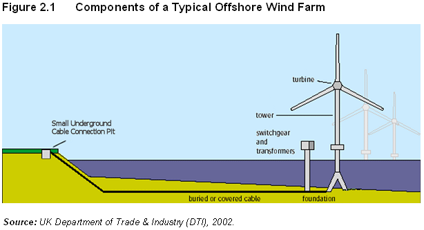
2.1.1.1 The offshore wind farm will be linked by sub sea cables that collect electricity from the various turbines, and via an offshore transformer, for transmission to shore. Figure 2.1 presents a schematic of the components of a typical offshore wind farm.
2.1.1.2 Table 2.1 summarises the interaction between the principal project elements and the offshore environment.
2.1.1.3 The potential for adverse impacts is largely associated with Project construction, the Project also offers potential positive impacts beyond the clean renewable energy to be generated, such as habitat enhancement for the marine ecosystem.
Table 2.1 Project Interaction Matrix
|
Aspect |
Water Quality |
Ecological (Terrestrial) |
Ecological (Marine) |
Fisheries |
Landscape & Visual |
Waste Management |
Cultural Heritage |
Hazard to Life |
Noise |
Air Quality |
|
|
Construction |
|||||||||||
|
Turbine |
Foundation |
|
|
|
|
|
|
|
|
|
|
|
Tower |
|
|
|
|
|
|
|
|
|
|
|
|
Offshore Transformer |
Foundation |
|
|
|
|
|
|
|
|
|
|
|
Unit |
|
|
|
|
|
|
|
|
|
|
|
|
Submarine Cables |
Jetting |
|
|
|
|
|
|
|
|
|
|
|
Cable Protection |
|
|
|
|
|
|
|
|
|
|
|
|
Operation |
|||||||||||
|
Turbine |
|
|
|
|
|
|
|
|
|
|
|
|
Offshore Transformer |
|
|
|
|
|
|
|
|
|
|
|
|
Submarine Cables |
|
|
|
|
|
|
|
|
|
|
|
2.1.2.1 The Project comprises the installation of up to 67 wind turbines purpose-built for the offshore environment.
2.1.2.2 It is typical in offshore wind farm EIA’s to factor in some flexibility in the final turbine choice as turbine technology is progressively advancing, meaning that larger and more efficient turbines may become available between completion of planning approvals and installation. Accordingly, while the base scenario for Project development assumes that 67 nos. of 3MW turbines shall be installed, the EIA Study also allows for installation of a smaller number of larger turbines – in this case, 40 nos. of 5MW turbines – that would approximately generate the same power.
2.1.2.3 At the present time a 3MW turbine is most likely to be used, however turbines up to 5MW are now being commercialised and therefore that option will be considered for the Project as an alternative design. Hence, it is the intention to select the exact turbine for Project development in the future after completion of a comprehensive tendering process that shall take into account environmental, technical and cost effectiveness criteria.
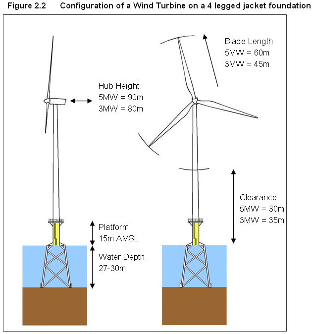
2.1.2.4 Figure 2.2 displays a typical modern wind turbine, and includes dimensions for both 3MW and 5MW turbine options.
2.1.2.5 A 3MW turbine would be approximately 125m high to the blade tip, while a 5MW turbine height to blade tip would be approximately 150m. Set against the increase in turbine height there would of course be a proportional decrease in the number of turbines required in the same Project area.
2.1.2.6 Regardless of the turbine option eventually installed, the dimensions of the marine foundation would be roughly the same and hence the construction phase impact assessment of marine environment issues (e.g., foundations installation effects on water quality and marine ecology) is based on the installation of 67 turbines as a worst case scenario. However, either scenario to install 40 turbines or 67 turbines of different dimensions may result in operational phase impacts on bird life (i.e., collision risk) or visual sensitivity, and accordingly both scenarios have been assessed in detail for these issues in sections 7 and 10, respectively.
2.1.2.7 The wind turbines would consist of the following components:
· Tower: a hollow tubular steel tower that supports a nacelle.
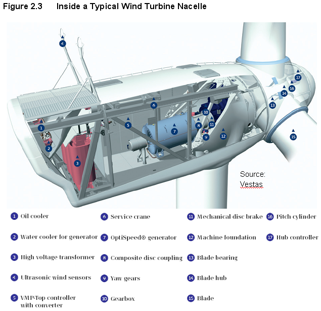
· Nacelle: contains the generator, control equipment and possibly a transformer (Figure 2.3 refers).
· Rotor & Blades: turbine blades on offshore turbines are always designed to feather independently to gain greater control and increase efficiency. They capture more wind at low wind speeds and spill wind to protect themselves during very high winds.
· Anemometer: measures wind direction and strength and feeds information to the control computer to adjust the blades and nacelle to extract maximum power.
· Controller: a computer controls all aspects of wind turbine operation without human input. Wind farms are typically unmanned, with the controller allowing remote access and control.
· Transformer: to transform the voltage from the generator (690 - 1,000V) to the array cable voltage of 33kV.
· Foundation: secured into the seabed to provide stability for the operating turbine.
2.1.2.8
Currently available wind
turbines are typically operational in wind speeds of between 3 and
2.1.2.9 The colour of the turbines is yet to be finalised, although they are expected to be coloured off-white, orange nacelle tops, and red tip markings on the blades. Consultation with relevant authorities will help decide a finalised colour scheme. Visual aspects are further discussed in Section 10.
2.1.2.10 The air-draft clearance of the turbine shall be over 30m, depending on the final tower height. This value is at the point where the blade passes the tower at the bottom of its rotation. Since no ship can pass through the turbine tower and the blades follow a rotational path, ships will experience a higher air draft in practice. For example, 20m from the turbine the air draft clearance would already be some 5m above the minimum.
2.1.2.11
In the
2.1.2.12 Dependent on the turbine type, quantities of mineral lubricating and hydraulic oils are typically required as follows:
· Gear box oil: Approximately 750 –1,000 litres of mineral oil.
· Hydraulic oil: Approximately 250 litres.
· Yaw/pitch motor oil: Approximately 20 litres.
· Transformer oil: Approximately 2,500 litres.
2.1.2.13 The nacelle, tower and rotor are designed so that any leaks are fully contained in the structure until they can be properly cleaned up.
2.1.2.14 Noise emissions from wind turbines can be separated into two categories: aerodynamic and mechanical noise. Aerodynamic noise occurs when the wind is passing the blades, while limited mechanical noise is emitted from the engineering components of the turbine such as gearbox and generator.
2.1.2.15 Whichever turbine is selected, the source power noise will be no greater than 110 dB (A) at hub height, in accordance with the industry standards. Given the distance separation between the Project and a distance of several kilometres to the nearest terrestrial noise sensitive receiver, construction and operational noise is not a key issues as regards fixed land-based receivers and is not discussed further. Underwater noise issues are discussed in section 6.
2.1.3 Offshore Transformer Platform
2.1.3.1 The proposed Project will require an offshore transformer substation. The indicative location shall be at the south of the turbine array, while the final position is to be confirmed on completion of the electrical design and consultation with the relevant authorities.
2.1.3.2 An offshore substation may comprise the following key components:
· 33kV and 132kV switchgear for array transmission and collection voltages.
· Power transformer(s).
· Shunt reactor(s).
· Supervisory control and data acquisition, and communications equipment.
· Back-up diesel generator and tank.
· Other auxiliaries and consumables.
2.1.3.3 The turbines and transformer station shall connect via 33kV cables, and the voltage at the transformer station shall be increased to 132kV for transmission to the CLP electricity grid in Tseung Kwan O.
2.1.3.4 Boat access points shall be provided and a helipad may be provided for emergency use.
2.1.3.5 The substation shall be placed on a similar foundation type as those use to support the turbines and shall be located approximately 15m above mean sea level, with a structure approximately 12m high and with a floor area of approximately 30m by 30m.
2.1.3.6 Dependent on the final design, the offshore transformer station will contain approximately the following quantities of oils and fuels:
· 2 x 33 / 132kV transformers, each with approximately 80,000 litres of oil.
· Diesel tank with approximately 100,000 litres of oil.
2.1.3.7 As with the turbines, any transformer station equipment containing significant amounts of oil will be designed so that any leaks are fully contained in the structure until they can be properly cleaned up.
2.1.4.1 Electrical cabling is split into two functions: collection (or array) and transmission. The array cables connect a series of turbines and are operated at a distribution level voltage, typically 33kV in the HKSAR. These collection cables connect all of the wind turbines to the offshore transformer platform. The voltage is increased to 132kV at the offshore substation and then 132kV transmission cables export the power to shore.
2.1.4.2
In order to reduce seabed
disturbance and potential maintenance requirements, 3-core cables are preferred
to single core cables and will be used for both the collection and transmission
cables. These cables will be buried to
between 3
2.1.4.3
The total length of collection
cable for the Project shall be 40 -
2.1.4.4 The exact layout and distance of the array cables will be decided in consultation with the relevant authorities prior to construction. The cables would be placed in such a way to avoid any identified potential objects or sensitivities.
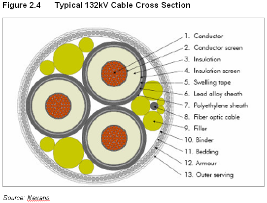
2.1.4.5 Due to the distance to shore and the specific cable operating conditions, a 132kV XLPE 3-core copper steel armoured cable is considered to be the best option. However, as a single 132kV cable cannot accommodate the maximum power output of the Project or the desire to have a degree of redundancy in the system, it is proposed that two such transmission cables are adopted.
2.1.4.6
Figure 2.4 displays in
cross-section a typical 132kV sub-sea cable with integrated fibre optic cable
which is around
2.2.1.1 The site selection process is probably the single most important method for mitigating potential environmental impacts from a wind farm. By choosing the right site it is possible to largely eliminate many potential impacts before they arise.
2.2.1.2
The potential for large-scale
land-based RE development in the HKSAR is limited due to lack of land
availability – most land being already developed, under conservation
protection, and / or simply ill-suited for large-scale deployment of RE. This is well demonstrated in the EIA’s
recently completed by CAPCO for its Commercial Scale Wind Turbine Pilot Demonstration
at Hei Ling Chau and Hong Kong Electric for their wind turbine on
2.2.1.3 HKSAR offshore waters offer more usable space, and of the offshore technologies available, wind power is viable for large-scale development.
2.2.1.4
In order to identify a site for
the wind farm it was first necessary to undertake a comprehensive site
selection process involving a synthesis of key design requirements and siting
constraints. The site selection conducted
for the Project included four main tasks, as detailed below.
2.2.2 Definition of Design Requirements
2.2.2.1 Initial calculations showed that to achieve the 1-2% RE target set out by the Hong Kong Government using offshore wind power it would be necessary to have between 150 – 400MW (depending on the final site wind speed and turbine selection).
2.2.2.2
Also, experience in
2.2.2.3 For these two significant reasons 150MW was set as the minimum project size.
2.2.2.4 The initial layout therefore consisted of an array of 50 wind turbines of 3MW capacity spaced approximately 560m apart.
2.2.3 Identification of High Level Screening Criteria
2.2.3.1 There are several factors that need to be considered when assessing the location of a potential offshore wind farm, these include:
· Physical Location: Mean wind speed, water depth, seabed character, sub-surface geology, coastal processes, and seascape / landscape assessment.
· Biological Environment: Protected areas, benthic, demersal and pelagic marine life, and birds.
· Human Environment: Utility infrastructure, economic development opportunities, tourism / leisure, archaeology, navigation, fisheries, port facilities, civil and military aviation, radar facilities (aviation and marine).
2.2.3.2 Whilst all of the above issues need to be considered, for any given location there will be issues that are insurmountable (e.g., water depth too deep to build in) and issues that, subject to study and adequate mitigation are surmountable (e.g., habitat management).
2.2.3.3
Marine environment criteria
were selected to conduct a site search that represented absolute or relative
constraints for offshore development.
The criteria included:
· Physical Infrastructure, including:
i.
Bridges and tunnels.
ii.
Proposed / potential reclamation areas.
iii.
Sub sea pipelines & cable routes.
· Constrained water-spaces, including:
iv.
Existing/proposed marine parks and
fisheries protection areas.
v.
Marine disposal grounds.
vi.
Restricted areas.
vii.
Existing artificial reef deployment areas.
viii.
Marine fish culture zones.
ix.
Log ponds.
· Shipping lanes, Fairways & Anchorages, including:
x.
Ocean-going vessel traffic routes.
xi.
Local vessel traffic routes.
xii.
Waters in proximity to marine radar installations.
· Productive fisheries areas, including:
xiii.
Fish culture zones.
xiv.
Fisheries Protection Areas.
xv.
Area with medium to high fisheries
productivity.
· Marine conservation areas, including:
xvi.
Core areas for Chinese White Dolphins.
xvii.
Core areas for Finless Porpoise.
xviii.
xix.
Key horseshoe crab habitat.
xx.
Areas of high coral value.
xxi.
Other habitats/species of conservation
importance.
2.2.3.4 It is important to note that the above list is not an exhaustive list of issues considered in the site search. The above list consisted of important environmental considerations which could be plotted on a Geographic Information System (GIS).
2.2.4.1 The various constraints identified were mapped and analysed using a GIS with which it was possible to identify potential areas for project development. Where appropriate, buffers were added to some selection criteria.
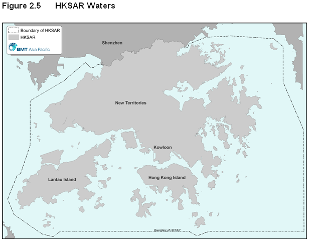
2.2.4.2
Figure 2.5 presents the area of
the HKSAR waters within the entirety of which the site selection process was
conducted.
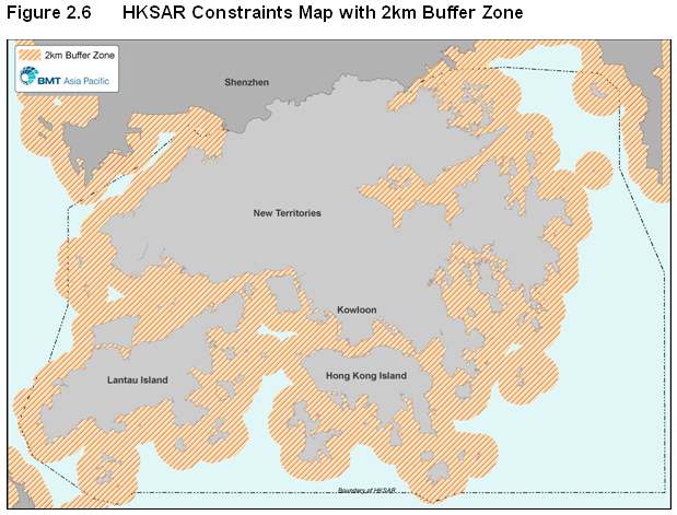
2.2.4.3
To begin with, a
· Island Based Ecological Receivers: The most likely sensitive ecological receivers are located on islands and coastal shorelines, therefore ensuring an adequate buffer early on reduces potential impact from the Project.
· Operational Noise: A wind farm of this scale would most likely only affect residents within 2km of a turbine so ruling out sites too close would be an efficient way to eliminate potential noise issues;
·
Water Use: Leisure craft, small fishing vessels and river trade vessels are
most commonly found within
·
Visual
Impact: Ruling out sites within
· Low Wind Areas: The output of a wind farm is sensitive to average wind speed, and land masses can cause wind shadow, so avoiding areas too close to shore is a good way to eliminate the lowest wind speed sites and therefore improve the cost effectiveness of a site.
2.2.4.4
Figure 2.6 presents the site
selection area with the application of the
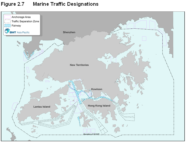
2.2.4.5 An offshore wind farm could interfere with marine operations through either physical obstruction, or radar and instrumentation degradation – all very important considerations in the busy waters of the HKSAR.
2.2.4.6 Figure 2.7 displays shipping lanes / fairways and anchorage areas that were included as fixed constraints so as to reduce the potential for physical interference with marine traffic.
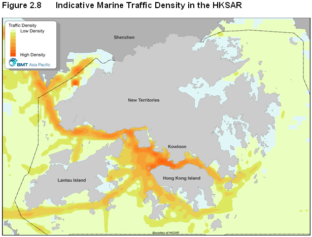
2.2.4.7 Figure 2.8 indicates the characteristic density of all marine traffic throughout HKSAR waters, including small boats through to ocean-going vessels.
2.2.4.8
It is evident that most areas
of
2.2.4.9 A Marine Navigation Safety Risk Assessment has been conducted in parallel with the EIA Study in order to understand the potential marine risks and to suggest suitable management options for the proposed Project. The approach and key findings with respect to Hazard to Life are presented in Appendix 2A.
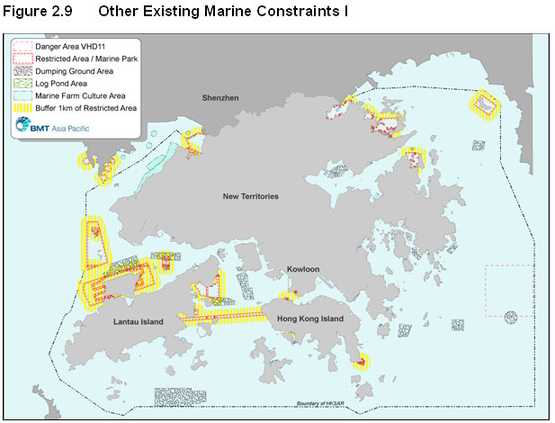
2.2.4.10 As well as marine traffic, other existing and proposed uses and areas that would restrict the proposed Project were considered. As displayed in Figure 2.9, such areas initially included marine disposal grounds, log-ponds and ‘restricted’ areas.
2.2.4.11 Consultation with the Civil Aviation Department (CAD) highlighted a constraint in eastern waters. This constraint is designated as Danger Area VHD-11 and CAD would object to any development in it.
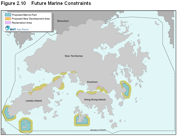
2.2.4.12
To this were added other
constraints including
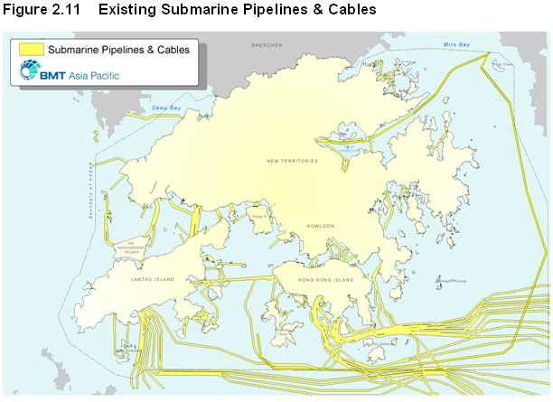
2.2.4.13 Existing and proposed pipelines / cables were included as constraints, with the application of a buffer, Figure 2.11 presents the result of such constraints mapping.
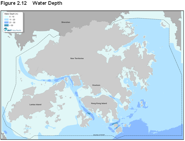
2.2.5.1
Water depth is an important
consideration because as water gets deeper foundation costs typically
increase. However, only considering the
very shallowest water greatly limits the scope for assessing potential areas. Whilst the deepest offshore wind turbines
developed to date as part of the European DOWNVinD program are 2 demonstrator
turbines in
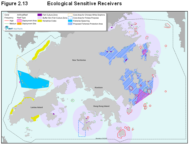
Ecological Sensitive Receivers
2.2.5.2 Various ecological sensitive receivers were identified for the constraints mapping exercise, including:
· Coral communities with medium / high abundance
· Artificial reefs
· Horseshoe crab / mudflat habitat
·
Core areas for Chinese White
Dolphins / Finless Porpoise
·
Migratory seabirds and breeding
bird colonies
2.2.5.3
Figure 2.13 displays the
consolidation of these ecological constraints.
The figure also includes the locations of fish culture zones (with
2.2.6 Identification of Potential Sites
2.2.6.1 The output of the GIS-enabled constraints mapping exercise was to effectively eliminate from consideration those areas of HKSAR waters where preliminary assessment would suggest that proposed Project development is unlikely to be environmentally, technically and / or economically viable.
2.2.6.2
Sites found to be relatively
free of constraints after analysis were compared against the desired site
parameters and were subject to sensitivity analysis in order to identify
potential ‘show stoppers’ that may render a site invalid. This aspect involved a review of various data
/ information sources and initial consultations to identify and evaluate other
constraints, including:
· Planning constraints
· Construction constraints
· Operational constraints
· Aviation and marine radar locations
· Aviation constraints
· Marine Archaeological considerations
· Noise considerations
· Landscape considerations
·
· Wind speeds and wave heights
·
Fishing resources in
2.2.6.3 The output of this exercise was the identification of three potential areas, as discussed under sub-section 2.3.
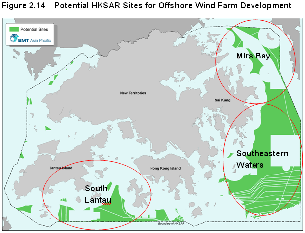
2.3.1.1
Figure 2.14 displays that the
output of the analysis task was the identification of three potential areas
that are relatively free of constraints
·
·
· Southeastern Waters
2.3.1.2 The advantages / disadvantages of each area is discussed in the following sub-sections.
2.3.2
2.3.2.1 There are a series of considerations that limit the attractiveness of this area:
· Insufficient water space for a large contiguous array of turbines.
· Proximity to fairways / shipping routes.
·
Existing helicopter low flying
routes between Hong Kong and
· Presence of telecom cables, marine disposal ground and fishing activity.
· Relatively high density of marine mammals compared to the other areas.
2.3.2.2 For the above reasons, Project development in this area was not preferred.
2.3.3
2.3.3.1 Considerations that limit the attractiveness of a site in Mirs Bay include:
· Insufficient water space for a contiguous array of turbines.
· Proximity to the approach to Yantian Port and potential interference with the effectiveness of the marine radar facility at Peng Chau.
· Proximity to marine ecology sensitive receivers such as the Peng Chau Marine Park, inshore fisheries in the NE New Territories
· Least favourable wind speed conditions due to high terrain (~ 800m) of the Mirs Bay catchment.
2.3.3.2 For the above reasons, Project development in this area was not preferred.
2.3.4.1 The Southeastern Waters was considered to offer the best potential for a commercial scale offshore wind farm development due to the large area of contiguous seabed and the relative lack of environmental sensitivity indicated by the site screening exercise.
2.3.4.2 Another core attribute of this location is the high anticipated mean near-sea level wind speed, which measured at Waglan Island is the highest in the HKSAR (HKO, 2002). Thus, this site offers the best potential to make use of this source of renewable energy.
2.3.4.3 In order to define a more specific area within Southeastern Waters site, a number of criteria were subject to further assessment. These were:
2.3.4.4 Grid Connection: To minimise offshore cabling works and electrical loses, an area of Southeastern waters closest to Tsueng Kwan O (the most viable grid cable connection point) were preferred.
2.3.4.5 Fishing: Locate the wind farm and alignment of the transmission cable away from areas of moderate / high fisheries productivity such as the Ninepin Islands.
2.3.4.6 Marine Traffic: Avoid areas with a high marine traffic density to reduce potential impacts on marine navigation safety.
2.3.4.7 Marine Radar: Orienting the turbine area with respect to the radar facilities at Waglan Island and Ping Chau to avoid significant radar shadowing where possible.
2.3.4.8 Visual Sensitivity: Locating the turbine area at the maximum distance from inhabited coastline viable to minimise its impact upon visual sensitive receivers.
2.3.4.9 Wind Direction: Orienting the turbine area such that it could take advantage of the prevailing wind direction.
2.3.4.10 Mud Dump: Orienting the turbine area such that it was out of the existing and still active mud dumping ground. This would reduce potential impact since the area would be subject to large and regular habitat disruption.
2.3.4.11 Aviation Constraints: Avoiding area “VHD 11” which has restrictions on infrastructure development in eastern waters.
2.3.4.12 Ecology: Avoid areas with sensitive or ecologically important habitats/species.
2.3.5.1 Table 2.2 summarises the relative constraints of the three short-listed site areas.
Table 2.2 Constraints Summary for the Short-listed Site Options
|
Short-listed sites |
Mapping Constraint Criteria |
|||||||
|
Water depth |
Proximity to islands |
Constrained water-spaces |
Shipping Lanes, fairways and Anchorage, aviation route |
High-Medium fisheries productivity |
Marine parks and ecologically valuable sites |
Distance from potential cable landing station |
Site space |
|
|
South Lantau |
|
|
|
|
|
|
|
|
|
Mirs Bay |
|
|
|
|
|
|
|
|
|
SE Waters |
|
|
|
|
|
|
|
|
2.4 Site Refinement and Layout
2.4.1.1 Before finalising the wind farm layout it is necessary to select a wind turbine as a reference base case because:
· Turbine spacing is a function of the rotor diameter of a turbine.
· Wind farm output is a function of the type and number of turbines.
· The environmental and economic aspects of the Project are a function of the number and type of wind turbine.
2.4.2.1
In general, in an offshore
context, it is preferable to have fewer larger wind turbines as this improves
project economics and limits environmental impact by reducing the Project
‘footprint’.
2.4.2.2
As introduced in section 2.1.2,
current offshore turbine capacity ranges from 3MW to 5MW. The 3MW class has been widely adopted while
the 5MW class is only just now being commercialised. At present it is unknown if 5MW class
turbines will be commercially available for the Project, and hence the EIA
Study has adopted the 3MW class turbine as a base case but has also assessed
the issues of adopting 5MW turbines as an alternative. This strategy of making
allowance for advances in offshore wind technology allows necessary flexibility
for Project development.
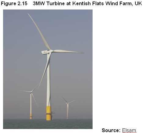
2.4.2.3
Figure 2.15 displays a 3MW
class turbine that represents the turbine base case.
2.4.2.4 By selecting a 3MW class turbine with a 90m rotor diameter it is possible to fix the initial spacing between the turbines at 540m and thus develop an indicative Project layout. Turbines must be spaced a certain distance apart to reduce interference between them which could lead to reduced power output and increased wear and tear.
2.4.3.1 Having decided on the general site area and suitable turbine class and spacing, an initial layout for the proposed Project was developed that formed the basis of the Project Profile submitted on the 3rd April 2006 along with an application for an EIA Study Brief (ESB 146/2006). This layout, displayed in Figure 2.16, was based on 50 x 3MW turbines to generate a total maximum output of 150MW.
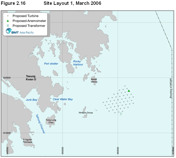
2.4.3.2 After some initial EIA work and consultations it was decided that the Project could be expanded from 50 to 60 turbines without significantly increasing the environmental impact, whilst significantly increasing the Projects output. This initial work also suggested that the Project could be moved further to the southeast in order to increase the distance from identified potentially sensitive receivers. At this stage the number of turbines was limited to 60 (180MW) as it was believed that this was the limit on the grid connection capacity.
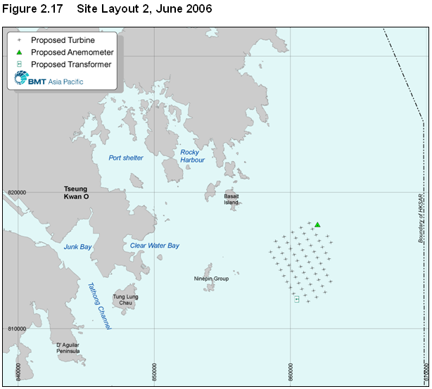
2.4.3.3 Having studied the wind data from Waglan Island and from satellite derived data sets, the turbines were re-arranged in a regular grid pattern; spaced at intervals of 450m in a NW/SE direction and 630m in an NE/SW direction. The layout change would achieve several objectives:
· Increase renewable energy generation by ~20% by increasing the number of turbines.
· Increase the array efficiency by aligning turbines into rows to complement the predominant wind direction.
· Increase the site distance from the Ninepins Islands and Basalt Island without moving closer to Victor Rock (a submerged rock outcrop), thereby further diminishing the potential for marine ecology impacts.
· Increase the site distance from shore without increasing the angle of visibility from shore, thereby further reducing its potential for visual impact.
2.4.3.4 Figure 2.17 displays the revised arrangement.
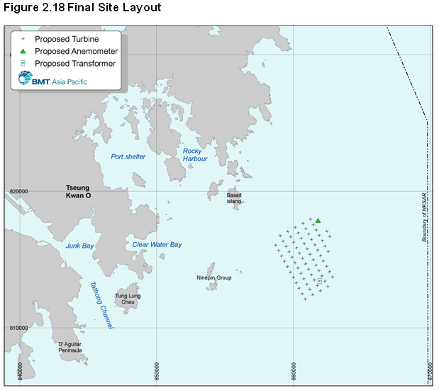
2.4.3.5 After further EIA work and consultations and detailed electrical grid studies it was decided to expand the proposed Project, from 60 to 67 turbines along the far southeast corner, and to change the alignment slightly.
2.4.3.6 This change would increase the generation of clean energy by a further 10%, and as the turbines added were to the far southeast of the site away from coastal / marine sensitive receivers it was considered there was a low increase in potential environmental impacts. Figure 2.18 displays the finalised layout of the turbine array.
2.5 Transmission Cable Routing
2.5.1.1 The collection cables connect a series of turbines and are operated at a suitable distribution level voltage, such as 33kV. These cables connect to an offshore transformer that increases the voltage to 132kV for relaying to shore via one or more transmission cables.
2.5.1.2 The collection cables would not leave the site and therefore are not considered further as part of the transmission cable landing options. For the transmission cable(s) it was necessary to select a route and landing point that struck the right balance between environmental sensitivity and cost effectiveness. Figure 2.19 displays four cable landing options that were considered, while Table 2.3 summarises the key issues for each option.
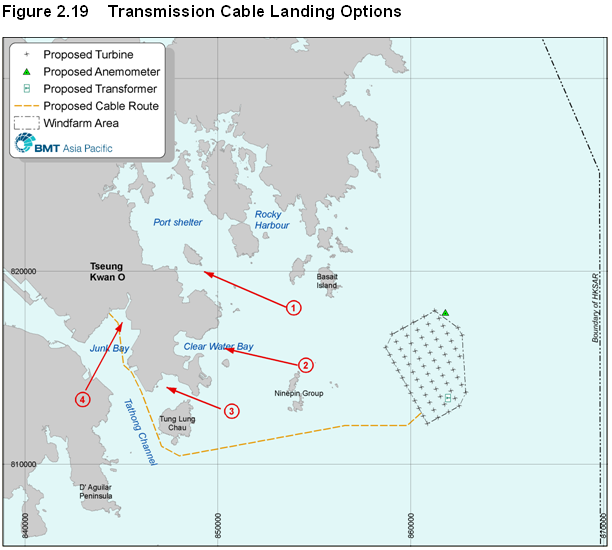
Table 2.3 Key Issues for Transmission Cable Landing Site Options
|
Option |
Landing Site |
Issues |
|
1 |
Port Shelter |
Would need to pass through the
environmentally sensitive Port Shelter, including through a proposed Marine
Park. |
|
2 |
Clearwater Bay Peninsula |
Requires laying a 132kV cable under Clearwater
Bay Road, which is undesirable due to service congestion. The site would also be beside a popular
recreational beach, and near a proposed Marine Park. |
|
3 |
TKO Area 137 |
Requires laying a 132kV underground cable from
Area 137 to the existing substation.
Service congestion constraints along Wan Po Road would not allow
additional cable work to be completed. |
|
4 |
Junk Bay |
The western side of the Bay presents the
best connection to the grid.
Discussion with CLP confirmed the grid location was able to handle the
predicted electricity to be generated by the Project and was unlikely to be
environmentally sensitive, being reclaimed land. |
2.5.1.3 In order to connect into the western area of Junk Bay (Tsueng Kwan O) it is necessary to land the cable at an appropriate location and then to run standard underground cables to the appropriate CLP grid connection.
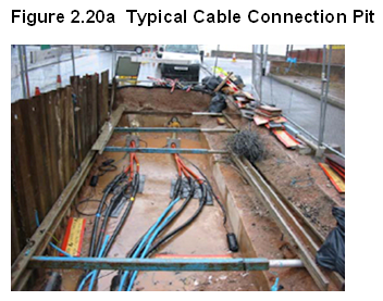
2.5.1.4
Figure 2.20a displays the
selected cable landing area at the west of
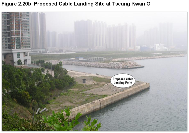
2.5.1.5 The onshore works will consist of a small underground cable connection pit (figure 2.20b) of dimension approximately 2m wide, 3m long and 1m, deep and then underground cabling to the appropriate CLP grid connection. There is no need to build a substation or other structure at the cable landing point. The area of the pit and underground cabling will be fully reinstated after installation. As the proposed cable connection pit will be constructed on reclaimed land (figure 2.20b), no natural terrestrial habitat or terrestrial habitat of conservation importance will be lost or affected. This work is very well understood in HK and is unlikely to cause significant environmental impact. This is not considered further in this EIA
2.5.2 Transmission Cable Alignment Options
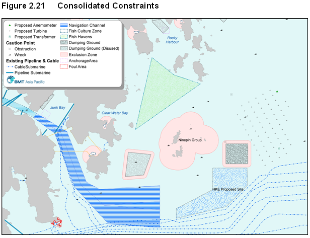
2.5.2.1 The alignment from the proposed wind farm to the cable landing area was selected after taking into consideration: a series of constraints including:
· Designated Traffic Separation Schemes (TSS)
· Dumping Sites
· Aquaculture & Artificial Reef Areas
· Submarine Pipeline & Cable Utilities
· Known Wrecks
· Exclusion Area around the Ninepins (exclusion to avoid key coral/fishing area)
· Anchorage Areas
· Potential Hong Kong Electric Site
· Location of substation within wind farm
2.5.2.2 The consolidation of these constraints is illustrated in Figure 2.21.
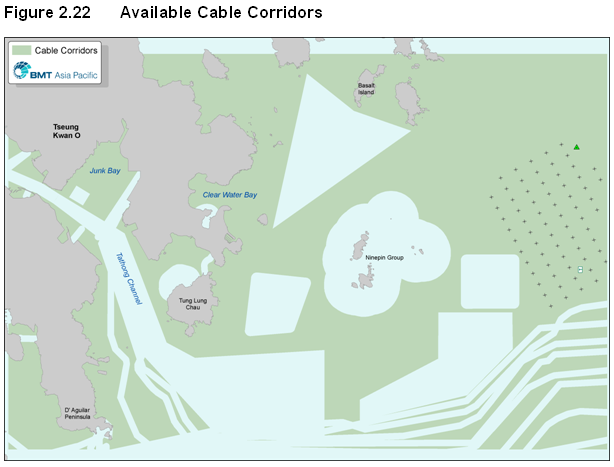
2.5.2.3 Figure 2.22 displays how the exclusion of these constraints enables the identification of available cable corridors.
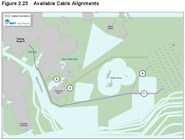
2.5.3.1 Figure 2.23 displays the four cable corridors that have been examined.
2.5.3.2 It is identified that none of the alignments are entirely free from constraints and cable / pipeline crossings are required for all four options. The options are broadly of a similar length.
2.5.3.3 Option 3 has four utility crossings, and passing north of Tung Lung Chau would require laying the cable over rock in the narrow gap between Tung Lung Chau and the Clearwater Bay peninsular. As such it is not preferred.
2.5.3.4 The shortest options with only 3 utility crossings are option 1 and option 4 that pass south of Tung Lung Chau. As the cable leads to a transformer platform, and there is a desire to minimise visual impact from all coastal sensitive receivers, a site for this platform at the south of the turbine array is desirable. As such, the option 1 alignment was preferred.
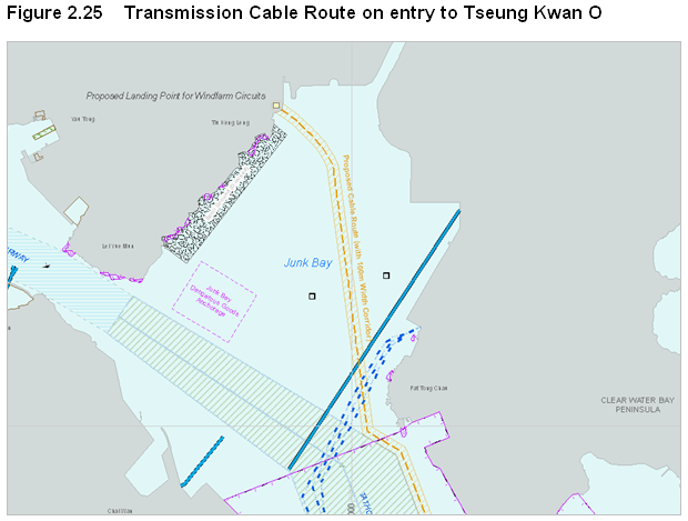
2.5.3.5
Figure 2.24 displays the
proposed transmission cable route, while Figure 2.25 displays details of
the proposed landing approach of the transmission cable at
2.6 The Baseline Site and Alternative Site Design
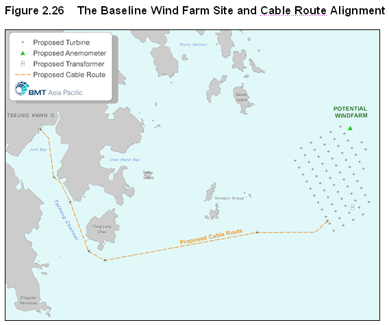
2.6.1.1 Combining the site selection outlined in section 2.4 together with the transmission cable routing process outlined in section 2.5 it was possible to form a baseline scenario for the EIA Study. Figure 2.26 displays the baseline site option, including the tentative location of the transformer platform within the array.
2.6.2 Proposed Hong Kong Geopark
2.6.2.1 The proposed Geopark in Hong Kong was a late stage addition to the wind farm site selection and cable alignment selection exercise.
2.6.2.2 The Geopark programme, initiated by United Nations Educational, Scientific and Cultural Organization (UNESCO), defines a geopark as a “geological site of special scientific significance, rarity or beauty; together with geological significance, these sites must also have high archaeological, ecological, historical or cultural value”.
2.6.2.3 Hong Kong’s Chief Executive announced in his 2008 policy address that Hong Kong’s first Geopark would be established,”with a view to better conserve our world class geological landscapes as well as promote geoeducation and geoscience popularization.”
2.6.2.4 The proposed Geopark will include two regions and eight areas in the northeastern New Territories and Sai Kung. Land areas will be designated as Special Areas under the Country Parks Ordinance including the Basalt, Bluff Islands, Wang Chau and Ninepins Islands. The waters around the above islands will be designated as marine parks under the Marine Parks Ordinance.
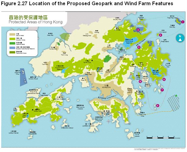
2.6.2.5 Figure 2.27 presents the proposed locations of the Geopark regions and areas. At present, the marine park boundaries are not yet fixed, however, a buffer area (marked in green and red dotted lines in northeastern waters and the Sai Kung region respectively) has been delineated to provide adequate protection to Geopark. Any construction work within the buffer areas is to be avoided.
2.6.2.6 After reviewing the site selection constraint mapping exercise it was determined that the proposed Geopark regions were already excluded from consideration as they overlapped existing constraints, in particular the 2km buffer around coastlines. Figure 2.27 shows that neither the proposed wind farm site nor the proposed cable alignment (including the <100m wide cable jetting works area) fall within the buffered areas and remain more than 1km away from the buffered area at all points. This confirms that no modification to the site selection or cable alignment exercises is necessary
2.6.2.7 Representative photomontages of the windfarm from the Geopark are presented in Figures 10.10 and 10.16.
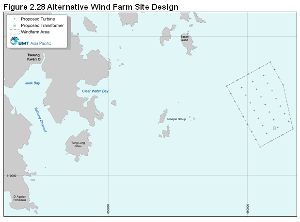
2.6.3.1 As referred earlier, a potential alternative layout comprising 40 nos. of 5MW turbines has also been considered in case such turbines become commercially available in the future.
2.6.3.2 This layout represents the maximum size of potential turbines and it could be that a compromise in Project layout and design between the 3MW and 5MW turbine scenarios is finally settled upon (e.g., 50 nos. of 4MW turbines which are 135m to tip height).
2.6.3.3 Regardless of the final size of turbine, the number of turbines and their size changes in proportion to the number needed since the site capacity is restricted to a power generation capacity of approximately 200MW. This restricts potential environmental impacts to being between the two potential site extremes (either the most number of smallest turbines or the least number of largest turbines).
2.6.3.4 The layout of 40 nos. of 5MW turbines is based on the same Project area as proposed for the 3MW layout, but incorporates an appropriate turbine spacing of 630m in a NW/SE direction and 890m in an NE/SW direction. The length and alignment of the associated transmission cable would be unchanged. Figure 2.28 displays the layout of the alternative site design.
2.7 Construction Options and Method Selection
2.7.1.1 This section considers the construction options methodology to be employed for the Project, and serves as the basis to review potential construction phase environmental impacts.
2.7.1.2 As previously identified, technological development is a constant feature of the rapidly developing offshore wind industry. Due to these advances in technology and installation methods it could be that lower impact methods and techniques become main-stream in the years between project planning / EIA stage and detailed design and construction. However, for the purposes of this EIA, a reasonable base-case construction scenario has been assumed.
2.7.1.3 The detailed technical impact assessments and evaluations, Section 3 of the EIA Report onwards, have been conducted against this reasonable base case scenario so as to assess impacts and propose applicable mitigation measures.
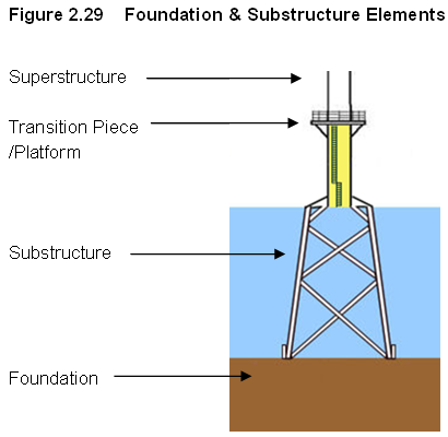
2.7.2.1
Table 2.4 summarises the foundation options, where the “foundation” proper is
the element that penetrates into the seabed and the “substructure” links the
foundation with the “superstructure” via a transition piece.
2.7.2.2 Figure 2.29 illustrates the basic configuration of a jacket structure as an example. It is anticipated that the same foundation concept shall be applied for turbines and the transformer platform.
Table 2.4 Foundation & Substructure Options
|
Water Depth (m) |
Concepts for Substructure |
Concepts for Foundation |
|
0-25 |
Mono tubular type |
Pile, suction caisson, gravity base |
|
> 25 |
Jacket/Tripod type |
Pile, suction caisson, gravity base |
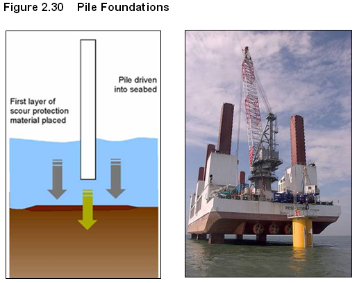
2.7.2.3 Piling is a well-known method and has been widely adopted for installation of offshore wind farms to date. For this method, one or more large steel tubular piles (2 – 5m in diameter for mono-piles and 1-2m in diameter for jacket driven piles) are driven into the seabed, as indicated by Figure 2.30.
2.7.2.4 The penetration depth would be designed to suit the environmental and soil conditions but would typically range from 20 to 40m. Scour around monopiles has occurred in shallow waters due to an increase in seabed velocity and erosion during wave action, and rock placement or grout mattresses are typically used to control this. Initial studies conducted for the HKOWF show that geological conditions would not be conducive to using piling.
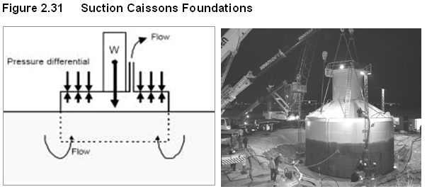
2.7.2.5 Recent research has highlighted a number of potential advantages of lightweight suction caisson foundations for the offshore wind industry. This type of foundation uses either a concrete or steel caisson (shaped like an over-turned bucket) that sinks into the seabed through a combination of its own weight and a differential pressure gradient resulting from applied suction. The suction caisson installation process produces no significant impacts on water quality. The water quality monitoring report of a suction caisson installation field trial at the wind farm site in June 2008 noted that, “no significant increase in turbidity and suspended solids values was observed during and after the installation works,” and concluded that “no significant adverse impact on water quality was induced by the installation (Cinotech, 2008).” Figure 2.31 displays the concept.
2.7.2.6 This type of foundation requires little or no site preparation. Initial studies show that the proposed Project site has suitable seabed conditions for this foundation type.
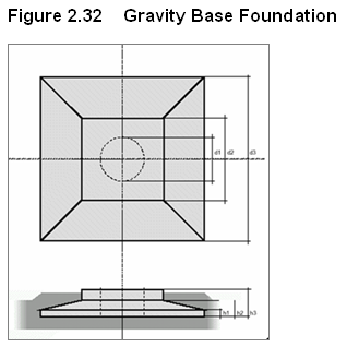
2.7.2.7 The concrete gravity foundation has been successfully used on a number of offshore wind farms in Europe. This type of foundation is similar to that used for onshore turbines where it relies on the sheer weight of a large base of concrete to hold the turbine in place. Figure 2.32 displays the concept.
2.7.2.8 This type of foundation requires seabed preparation and needs to be placed on stable and strong ground, whereas the seabed at the proposed Project site mostly comprises soft mud to at least 10m depth. As a significant volume of sediment would need to be excavated prior to foundation installation, this foundation type is not preferred due to the potential environmental impact.
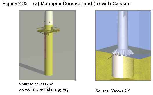
2.7.3.1 This type of substructure is usually a 4-7m diameter tubular steel section. If the pile is chosen as the foundation concept, the substructure will be the extension of the pile above the seabed, this is referred to as a monopile illustrated in Figure 2.33 (a). This single tubular section can also be used together with a caisson type foundation and is called a ‘monopod’, as shown in Figure 2.33 (b).
2.7.3.2 This type of superstructure is simple, however, in deeper water or with very large turbines it may not be a practical or efficient option as the diameter of the pile may become very large and exceed the limitations on the size of equipment that exists to manufacture, transport and install such large diameter piles.
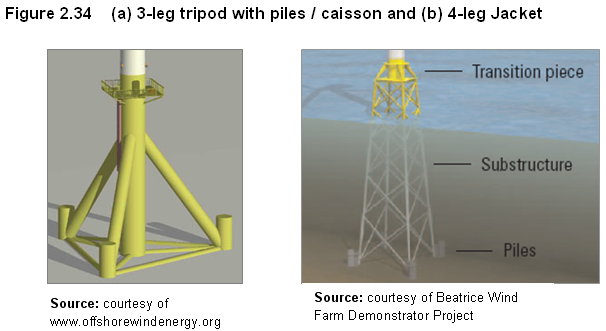
2.7.3.3 The jacket / tripod concept consists of a 3 or 4 legged structure made of cylindrical steel tubes as illustrated in Figure 2.34. The jacket can have either vertical or inclined legs, and the base width can be adjusted to suit actual site conditions.
2.7.3.4 This concept is widely applied in the offshore oil & gas industry, and has recently been adopted by the Beatrice Wind Farm Demonstrator Project in the UK where 4 leg jackets were used to support 5MW turbines.
2.7.4
Evaluation
of Foundation & Substructure Options
2.7.4.1 A preliminary review of the foundation options was completed to assist the EIA Study. Table 2.5 summarises the relative technical and environmental benefits and disbenefits of each option.
Table 2.5 Summary of Foundation & Substructure Options
|
Type |
Technical and Environmental benefits |
Technical and Environmental Disbenefits |
|
Pile Foundation |
Well understood and proven technique No seabed preparation required |
Underwater noise from piling can impact pelagic species May not be feasible in deep water / shallow rock-head sites |
|
Suction Caisson Foundation |
Less marine plant required Easy to commission and decommission No seabed preparation, piling or dredging required |
No major disbenefit |
|
Gravity Base Foundation |
Well understood and proven technique |
Significant amounts of dredging and site preparation works can impact water quality and therefore affect ecology Unlikely to be economically viable |
|
Monopile sub-structure |
Well understood and proven technique Small structure |
Not technically feasible at site due to water depth/ground condition combination |
|
Tripod / jacket sub-structure |
Complex structure allows for more marine growth Suitable for water depth at site |
No major disbenefit |
2.7.4.2 It can be seen from Table 2.5 that suction caisson foundations represent the least impact option. Gravity foundations would require significant ground preparation and dredging, whilst pile foundations would create more noise impact through hammering and driving. For this reason the suction caisson foundation is the preferred solution and will be adopted as the ‘base case’ for Project development.
2.7.4.3 For the suction caisson substructure options, a 4-legged jacket would have marginally higher impact (due to being slightly larger with one extra suction caisson) than a 3 legged tripod / jacket and has therefore been adopted as the base case option for this EIA Study.
2.7.4.4 Opportunities to adopt improved foundation designs will be considered during the detailed tendering for the Project and the exact foundation option selected will be submitted to the relevant authority for approval prior to construction.
2.7.5
‘Base
Case’ Development Scenario: Jacket with Suction Caisson Foundation
2.7.5.1 The jacket substructure with suction caisson foundation is suitable for installation at the proposed Project site. Indicative dimensions are as follows:
· Each suction caisson diameter: ~ 12 - 15m
· Substructure + foundation weight: 1,000 - 1,300 tonnes
· Seabed penetration: ~ 12m (incl. ~ 5m self-weight penetration)
· Overall height: ~ 57m (12m penetration + 30m water depth + 15m above mean sea level)
· Overall width: ~30m at base tapering off to 5-10m at sea level
2.8 Installation of Components
2.8.1.1 The following section presents an overview of anticipated construction operation based on prior experience at offshore wind farms in Europe, and oil & gas operations worldwide.
2.8.1.2 It should be noted that the project will not require major manufacturing of components in Hong Kong. Components will be prefabricated overseas and on the mainland and imported to Hong Kong. On the quay side or in approved yards some major components may require assembling, but this will be limited to the use of bolts and minor welding. There will be no significant waste arising from the assembly process. This aspect is further discussed in section 3.
2.8.2
Installation
of Foundations
2.8.2.1 After completion of the jacket substructure fabrication at a shipyard in Southern China, or elsewhere in the region, suction pump skids are installed on top of the suction cans. A crane would then be used to lower jacket substructure with suction cans into the sea. If required, auxiliary flotation tanks would be installed to assist floatation of the jacket substructure in case the buoyancy of the sealed structure alone is insufficient. The jacket substructure would be towed to site by tug boats.
2.8.2.2 Once the jacket substructure arrives at the site, it would be positioned by the tug boat(s). A heavy lift vessel (HLV) with a crane would be positioned ready to lift the semi submerged jacket substructure in horizontal position and in conjunction with a suitable ballasting systems the jacket substructure would be upended and lowered into place
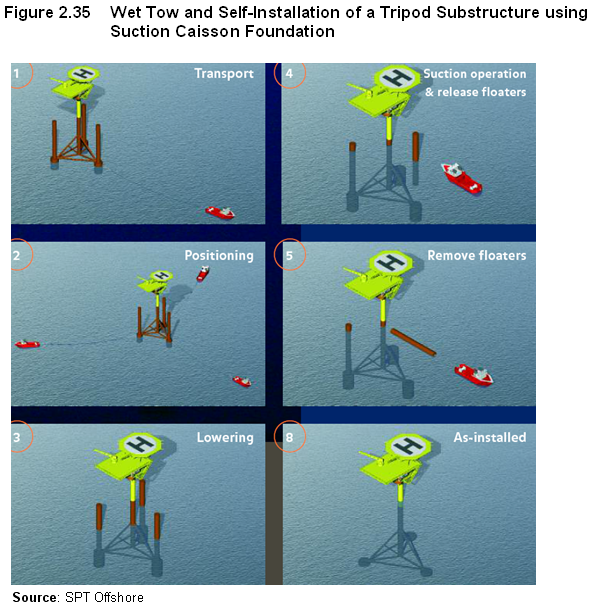
2.8.2.3 Alternatively, if the jacket can be floated to the site in a vertical position, the jacket substructure can be lowered to the seabed by using suitable ballast systems, thus precluding the need for a crane vessel. Figure 2.35 displays this concept.
2.8.2.4 The jacket substructure will be tied down on a flat top cargo barge and towed out by a number of tugboats. When the jacket substructure arrives at the site, the jacket substructure will be lifted by the HLV crane and lowered down to the seabed in a controlled manner.
2.8.2.5
Alternatively, the jacket
substructure can be connected to the HLV crane at port before sailing. Buoyancy tanks can be used to reduce the lift
load. The HLV may be towed to site by a
number of tugboats if it is not self-propelled.
The Jacket substructure can then be lowered down to the seabed directly
by the crane of the HLV.
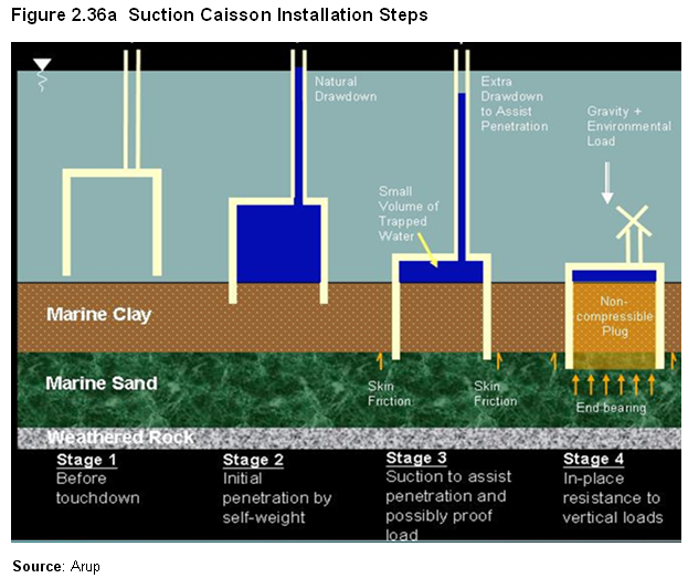
2.8.2.6 After the suction cans touches down on the seabed, they are allowed to penetrate the seabed under their own weight with the vent valves left open. Once they have penetrated as far as they can under their own weight, the vent valves would be closed and the water trapped within the suction cans would be pumped out by the suction pumps installed on the top of the suction cans in a controlled manner.
2.8.2.7 The suction pressure applied will reduce the pressure within the suction cans and this will create a downward water pressure differential which will force the cans to penetrate further into the soil. Figure 2.36a and b shows the stages of a suction caisson installation.
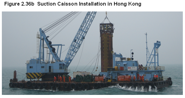
2.8.2.8 The total amount of water expected to be pumped out of each foundation (comprised of 4 suction caissons) is not expected to exceed 8,500m3 and the pumping rate would not exceed 300 m3 / hour per pump, or 1,200 m3 / hour per foundation. The process does not produce any significant noise or vibration.
2.8.2.9 Industry experience shows that the controlled penetration of the foundation can be managed at a slow rate (approx 2-10m/hr). This means that the seabed within the foundation is not being significantly perturbed, and consequently the water being pumped out of foundation is mainly seawater, without significant sediment content. For this reason it is not necessary to filter the seawater being removed from the foundations during the controlled pumping. This has been verified during an onsite trial conducted in May 2008. Further details are presented in section 4.
2.8.2.10 Once the suction cans reach the design penetration depth, the installation is complete. After full penetration of the suction can, suction is stopped and all vents can be sealed. The suction pump skids will be undocked and lifted back to the construction vessel for transfer back to port for the operation to begin again.
Installation Monitoring and Control
2.8.2.11 The jacket substructure installation would be monitored and controlled by specialist instrumentation equipped with the suction pumps such as pressure sensors, seabed elevation reference sensors, inclinometers, echo sounders etc. The applied suction pressure, penetration depth, movement of the soil plug within the suction cans, X-Y inclination of the jacket substructure would be displayed in real-time, and monitored.
2.8.2.12 It is anticipated that it will take around 1-2 days to complete each foundation installation including tow out time and this will be repeated approximately 68 times for the Project.
Suction Caisson Test in Hong Kong
2.8.2.13 In May 2008, project partner CLP led on the testing of a suction caisson at the proposed project location. The test was carried out under the supervision of various Government Departments, including the Buildings Department (structural aspects) and EPD (environmental aspects).
2.8.2.14 The test involved the installation of a full scale suction caisson foundation. The foundation was left for 45 days and then removed. During the installation water quality sampling and video monitoring was carried out to inform the EIA water quality modelling assumptions. Building Department was also there to verify the tension test carried out to verify load bearing parameters - all of which met or exceeded design requirements.
2.8.3
Installation
of Wind Turbines
2.8.3.1 The turbines and towers are expected to be manufactured in Mainland China or overseas and shipped to Hong Kong directly or through an interim port. These components shall be installed by one of two methods. The most likely method is that they will be loaded onto a heavy lift vessel (HLV), barge or jack up, about 4 – 6 at a time.
2.8.3.2
Figure 2.37 displays a heavy lift
operation for turbine installation in
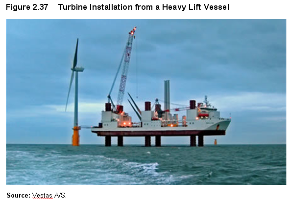
2.8.3.3 The HLV will manoeuvre into position alongside the installed foundations and lift the turbine sections into place. There will typically be 3 or 4 lifts per turbine, starting with the tower section (in one or two pieces) followed by the nacelle with two blades preinstalled and then the final blade. Experience has shown that the HLV can manoeuvre, position and erect an entire turbine unit within 2 working days.
2.8.3.4 On completion, the HLV will move to the next location and repeat the process. In total this will be repeated up to 67 times, with the vessel returning to the designated port to “reload”, as required.
2.8.3.5 The alternative method, which is still being commercialised, would see the turbines being erected on top of the foundation and then wet towed to the site as outlined in section 2.8.2.1.
2.8.4
Installation
of Offshore Transformer Station
2.8.4.1 The offshore transformer station shall be manufactured and fitted-out prior to being positioned on a barge / HLV for installation. The HLV may be the same unit used for the foundation and tower installation, or more likely it will have a larger lifting capacity and will be specially brought in for the transformer lift. The total weight of the station will be in the order of 700 – 1,200 tonnes, and it will be lifted in a single operation.
2.8.5.1 The sub sea cables must be protected in order to prevent damage from anchors and other potential objects. This is generally achieved by burying the cable to an appropriate depth and using cables with in-built amour protection. In some cases, where anchor damage is believed to be a high risk, additional protection above the cable may be desirable.
2.8.5.2 Studies of anchor damage risk specifically conducted for the Project by BMT indicate that it will be necessary to provide additional protection for the section of the transmission cable in Tseung Kwan O. Figure 2.38 displays the cable section which is approximately 3km long.
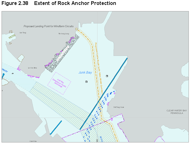
2.8.5.3 For the remaining transmission cable and all of the array cables the study indicates that burial of 3 and 5 metres will provide sufficient protection. The two transmission cables will be buried approximately 50m apart within the 200m surveyed corridor, except in the area within TKO and rock anchor protection where they will be buried in the same trench.
Installation of Transmission Cable with Extra Protection
2.8.5.4 One of two methods may be adopted for anchor protection in Junk Bay, with the preferred method to be subject to study by the work contractor before construction.
2.8.5.5 Method 1: Rock Amour Protection
2.8.5.6 The cable burial method will involve the dredging of a trapezoidal trench approximately side slope 3m deep. The volume to be dredged will be approximately 135,000m3 (a trapezoid with 1/4 side slope gradient, 3m wide at the bottom and 27m at the top and 3km long).
2.8.5.7 The work would be undertaken mainly by two grab dredgers typically using an 11 m3 grab with a protecting silt screen. Marine mud would be extracted by grab dredging followed by backfilling with rocks. The marine mud disposal is discussed in more detail in section 3. The cable segment (cable size of approximately 200 mm in diameter) will be laid from a barge. As the cable approaches the landing point the cable end will be fed by divers into a cable duct entrance (to be covered in a separate submission as part of the onshore cable works).
2.8.5.8 The dredging rate is not expected to exceed 6,300 m3 per day for the grab dredger. The total volume of dredged materials is expected to be no more than a total of 135,000 m3.
2.8.5.9 Once dredging is complete the cables will be laid and then the rock armour protection will be placed in a controlled manner such that the top of the trench is level with the seabed to avoid creating an obstruction on the seabed. Figure 2.39 illustrates the cross-section of a typical rock armour protection.
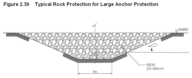
2.8.5.10
Method 2: Concrete Slab Protection
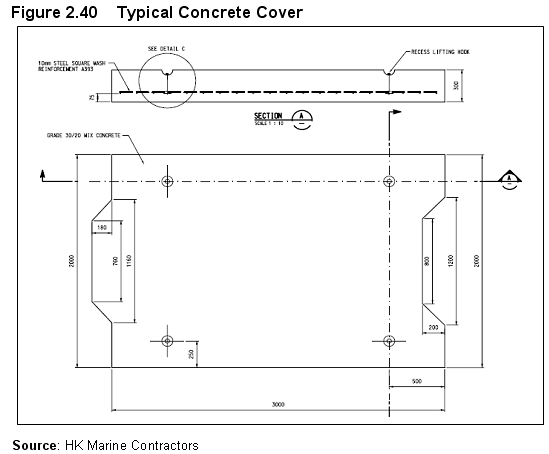
2.8.5.11 In this method the cables are first jetted 3-5m into the seabed (the jetting method is explained in more detail in the next section) before having concrete slabs positioned on top. The slabs would be approximately 2-3 m wide by 30-50 cm thick and would form a protective blanket over the cables (Figure 2.40 refers). However, the ability to utilise this method is subject to the future contractor’s detailed study to ensure the level of protection offered would be adequate.
2.8.5.12 Whichever method is chosen the construction would be expected to last approximately 4 months for this part of the cable work.
2.8.6
Installation
of Remaining Offshore Transmission Cables
2.8.6.1
The jetting method will be used
to install the rest of the transmission cable and the collection cables to a
depth of up to 5m. Jetting is a well
proven technique that causes minimal disturbance. This fact has been recognized
in Hong Kong by the government’s acceptance of project profiles for other
similar cable installation operations without requiring further EIAs. These
projects include the South Lantau Asia-America Gateway (AAG) Cable Network (EGS,
2007) and the Proposed 132kV
2.8.6.2 Jetting works by using a high-pressure water jet to fluidise the seabed, and then placing the cable so that it sinks under its own weight. Electrical cable installation via this technique has been frequently practised in the HKSAR, with recent studies having identified that potential disturbances from such minor works within the marine environment potential are likely to be minimal, localised and of a short duration.[*] The jetting speed would be expected to be a maximum of 150m/hour. The remaining approximately 21km of offshore transmission cable it is expected to take up to 2 months per cable to complete.
2.8.7
Installation
of Collection Cables
2.8.7.1 The jetting method will also be used to install the collection cables to a depth of up to 5m. The total length of collection cable for the Project shall be 40 - 50km. This work would either be carried out in parallel with the foundation installation or shortly afterwards.
2.8.7.2 Cable segments between each turbine are expected to be installed in less than one day. This will include the jetting between each turbine and the use of divers to thread the cable into each turbine foundation at the seabed.
2.9.1.1 There are many offshore wind farms operating in Europe, and the construction methodology used for each one is broadly similar and well understood. The example of these projects will be closely followed in the installation of the proposed Project.
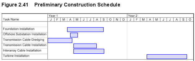
2.9.1.2 The full Project construction is expected to take place over a period of two years. Figure 2.41 presents an indicative construction schedule which shall be subject to logistics arrangement and weather conditions.
2.9.1.3 Due to the nature of offshore work construction will not be possible all year round at the site. Construction will probably be focused over the Spring and Summer months when wind and wave conditions permit more regular access. In the Winter increased wind speeds and associated wave heights make construction much more difficult, giving an approximate construction window of 6 months in a year. This is fairly typical for offshore projects. The exact construction schedule will be confirmed prior to construction commencing.
2.9.1.4 The advantage of building over two years with a gap between construction seasons is that if there are unexpected delays in the first year then some limited activity could continue over the winter months if necessary.
2.9.1.5 Where possible, much of the work shall be run in parallel. For example, foundation installation and construction of the offshore substation can progress while transmission cabling is taking place.
2.10 Offshore Construction Logistics
2.10.1.1 The construction vessels that are to be used will be determined after tendering by the contractor in charge of the construction of the Project. Table 2.6 presents options for the anticipated construction vessel types.
Table 2.6 Anticipated Construction Vessel Types
|
Activity |
Construction Vessel |
Support Vessels |
|
Foundations |
Heavy Lift Vessel (HLV) |
Tug boats and work boats |
|
Wind turbines |
HLV |
Tug boats and work boats |
|
Offshore Substation |
HLV |
Tug boats and work boats |
|
Cable Laying |
Dedicated cable laying
vessel or adapted barge and a remote operated vehicle |
/ |
|
General |
Work Boats |
/ |
2.10.1.2 Table 2.7 presents the forecast number of construction vessel movements from port to site. Approximately 120 HLV movements are anticipated over the two year construction period, equivalent to approximately one every 3 days. There are also likely to be approximately 3,360 support vessel movements over the same 2 year period, or approximately 4-5 a day on average.
2.10.1.3
Work on the site will occur in
concentrated periods rather than continuously, and it might be that on the very
busiest days up to 15 vessels could be active.
Relative to the maximum existing marine traffic volume in the Project
area of approximately 20 vessels / hour, the peak marine construction marine
traffic volume could be seen as a significant increase over the baseline, but
the actual forecast density of marine vessels within the 15km2
Project area would still be extremely low.
2.10.1.4
The
primary potential environmental impacts from the vessels will be atmospheric
emissions and operational waste.
Operational waste is discussed in section 3, while vessel emissions are
not considered significant given the low level of marine traffic in the HKSAR
context (i.e., > 15,000 vessel movements per day HKSAR-wide) and the
emissions savings that would be enabled by Project development.
Table 2.7 Number of Anticipated Vessel Movements from Port to Site
|
|
Number of movements |
Comment |
|
Heavy Vessels (Jack-up,
Barge, Installation Vessels) |
||
|
Foundation & transformer |
89 |
2 for transformer 1 foundation at a time being towered/carried to site (worst case) An estimated 20 for HLV with crane |
|
Transmission cables |
4 |
2 visits per cable |
|
Array cables |
10 |
6-7 turbines per visit |
|
Wind turbines |
17 |
4 per visit |
|
Total |
120 |
|
|
Support Vessels |
||
|
Anchor handling and towing support vessel |
240 |
Average of 2 per HLV |
|
Commissioning |
200 |
One movement transfers 2 crews each able to service one turbine per day. Each turbine visited approximately 6 times. |
|
Guard vessel/security |
730 |
1 visit per day over 2 year period |
|
Crew Transfer |
1460 |
2 visit per day over 2 year period |
|
Miscellaneous |
730 |
1 visit per day over 2 year period |
|
Total |
3,360 |
|
2.10.2
Port
Facilities
2.10.2.1 The port to be used for construction support is yet to be finalised, although there are several options in and around the PRD and the HKSAR. The selection is not expected to be finalised in the coming few years and the final choice will depend on availability and the construction schedule.
2.10.2.2 For the purposes of this EIA Study, the port is not a material consideration.
2.11 Operations and Maintenance
2.11.1.1 The Project will be designed to remain operational with minimal maintenance and supervision over its lifetime. Each turbine has a self-regulating system installed to control all of its operations, and in the event of a fault the system diagnoses the problem and determines an appropriate action, shutting down if necessary.
2.11.1.2 All data and information recorded at the Project site shall be continually monitored by the operators. This includes fault diagnostics in addition to standard operating information such as wind speed and power output. Upon notification of a problem, engineers can respond with the correct maintenance required.
2.11.2
Expected
Operational Activities
2.11.2.1 Project operations activities can be broken down into the following three main categories:
· Scheduled maintenance: This will take place once a year for each turbine and the transformer platform. This activity involves conducting minor oil changes, replacing perishables etc… Scheduled maintenance is likely to occur during the spring and summer period when sea conditions are calmest.
· Minor maintenance: This activity covers visits which are unscheduled but which can be carried out by engineers visiting turbines without additional heavy vessel support. This sort of activity would cover manual start-ups after a shut down, replacing minor components, minor repairs, inspections etc… The transformer platform may also have occasional minor maintenance.
· Major repairs: This activity covers repairs that require additional heavy vessel support, such as the replacement of a gearbox, blade and generator or in the case of the transformer platform a major component. It is expected that this activity will be rare.
2.11.3
Operations
Support Vessels
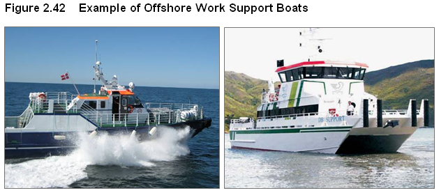
2.11.3.1 Minor and scheduled maintenance will be conducted using work-boats to despatch a minimum of 2 engineers to each turbine, while the boat remains on site until pick-up.
2.11.3.2 Figure 2.42 displays an example of an offshore work boat, while the exact specification is under development. Table 2.8 summarises the anticipated number of operational work-boats required.
Table
2.8 Es
|
|
Number of vessels required per day |
Comment |
|
Scheduled Maintenance |
2-3 |
To take advantage of weather windows up to 3 vessels might be deployed simultaneously |
|
Minor Maintenance |
1-2 |
Minor maintenance would take place as necessary and up to 2 vessels may be deployed. If minor maintenance is needed at the same time as regular maintenance then the regular maintenance vessels would be used |
2.11.4.1 Maintaining the Project will take place from a nearby port facility. Given the low volume of expected vessel movements outlined above, the choice of port facility is not anticipated to contribute to any significant environmental impact.
2.11.4.2 The turbines and offshore transformer platform will have emergency accommodation in the event that weather requires engineers to remain on site, although none of the infrastructure is expected to have permanent habitation quarters.
2.11.4.3 The operational activities will require a full time staff of approximately 10 at the port / operations facility and an engineering staff of approximately 20 people, excluding boat drivers.
2.11.5 Impact on Local Marine Users
2.11.5.1 In order to formulate an appropriate and effective strategy to manage the potential safety risks posed on other users of the sea, BMT has conducted a Marine Navigational Safety Risk Assessment (MNSRA) to address the following questions:
· Where to site it?
· How to mark it?
· How to manage it?
2.11.5.2 Marine navigation issues have been closely integrated into the site selection described previously, while the marking and management of the site has been informed by a risk assessment conducted with respect to international guidelines (DTI, 2005) and in accordance with a methodology agreed by Marine Department.
2.11.5.3 The MNSRA included a comprehensive assessment of the marine navigation safety risk implications arising from the establishment of an offshore wind farm in south-eastern Hong Kong waters and included the identification of key hazards and the quantification of associated risks. It was identified that the impact of the proposed Wind Farm on marine users is minor, and Acceptable (with respect to local guidance (EIAO)), given the design features and management measures proposed to accompany the development.
2.11.5.4 Appendix 2A presents the details and the key findings of the MNSRA.
Cinotech (2008). Hong
Kong Offshore Wind Farm in Southeastern Waters Trial Test for Installation of
Suction Can Foundation Water Quality Monitoring Report, Cinotech,
2.12.1.1
DTI (2005). Guidance on the Assessment of the Impact of Offshore Windfarms: Methodology for Assessing the Marine
Navigational Safety Risks of Offshore Wind Farms. Department of
EGS
(2007). Asia-America
Gateway (AAG) Cable Network, South Lantau Project Profile, EGS (Asia) Ltd.,
Hong Kong
2.12.1.2 EIAO. Annex 4, Technical Memorandum on Environmental Impact Assessment Process, EIA Ordinance Cap 499, S.16.