6 Sewerage and Sewage Treatment
Implications
6.2 Environmental
Legislations, Standards and Guidelines
6.3 Description
of the Environment
6.5 Identification
and Evaluation of Sewage and Sewerage Treatment Implications
6.7
Conclusions
6 Sewerage and Sewage Treatment Implications
This section presents the assessment of
potential sewerage and sewage treatment implementations, which may arise from
the Project.
Under the existing condition, there is no public sewerage system in
the vicinity of proposed development site. The proposed LMC Loop development will generate
additional sewage flows and loads which cannot be handled by the existing Yuen Long Sewage Treatment
Works (YLSTW) or Shek Wu Hui Sewage Treatment
Works (SWHSTW). In order to meet the prevailing water quality policy
for ensuring “no net increase in pollution load” to Deep Bay, construction of a
new onsite STW and upgrading of SWHSTW are
proposed.
The sewerage and sewage treatment implications
have been conducted in accordance with the requirements of Annexes 14 of the
TM-EIAO and EPD Report No. EPD/TP
1/05 Guidelines for Estimating Sewage Flows (GESF) for Sewerage Infrastructure
Planning Version 1.0
as well as the requirements set out in Clause 3.4.5 and 3.4.7 of the EIA Study
Brief.
6.2 Environmental Legislations, Standards and Guidelines
The relevant legislation, standards and
guidelines related to sewerage and sewage treatment implications include:
· Water Pollution Control Ordinance (WPCO) CAP 358;
· Technical Memorandum for Effluents Discharged into Drainage and Sewerage Systems Inland and Coastal Waters (TM-DSS)
· Environmental Impact Assessment Ordinance (EIAO) (CAP. 499), Technical Memorandum on Environmental Impact Assessment Process (TM-EIAO);
· No Net Increase in Pollution Loads Requirement in Deep Bay;
·
· EPD Report No. EPD/TP 1/05 Guidelines for Estimating Sewage Flows (GESF) for Sewerage Infrastructure Planning Version 1.0
6.3 Description of the Environment
6.3.1 Existing Site Condition
As a result of the training of the SZ River, an area of about 87.7 ha which previously lied to the north of the river course became situated to the south of the re-aligned river course. The area, commonly known as the LMC Loop, was used as a disposal site for mud extracted from the river training work, some of which might be contaminated.
The Study Area comprises the area within the LMC Loop together with
the adjoining area in Hong Kong and is shown on Figure 1.1. The LMC Loop
is located near several major cross-boundary transport nodes including the LMC
Boundary Control Point (BCP), the MTR LMC Station and the San Tin
Interchange. To the north across the SZ
River is the Huanggang Port of SZ. To the southwest is the
Site characteristics of the LMC Loop and its surrounding land uses are:
· predominantly flat land with grasses and shrubs on it.
· surrounding area mainly rural in nature, comprising mostly wetland, natural landscape, hilly terrain, woodland, village settlements, agricultural land and fishponds.
·
the Mai Po Nature Reserve, forming part of the Ramsar
Site, is at about
· the LMC BCP and the LMC Spur Line BCP are located in close proximity to the southwest.
· across the SZ River to the north is the Futian Central Business District of SZ, where the Huanggang Station of SZ Metro Line can be connected to the LMC Station easily via the LMC Spur Line BCP.
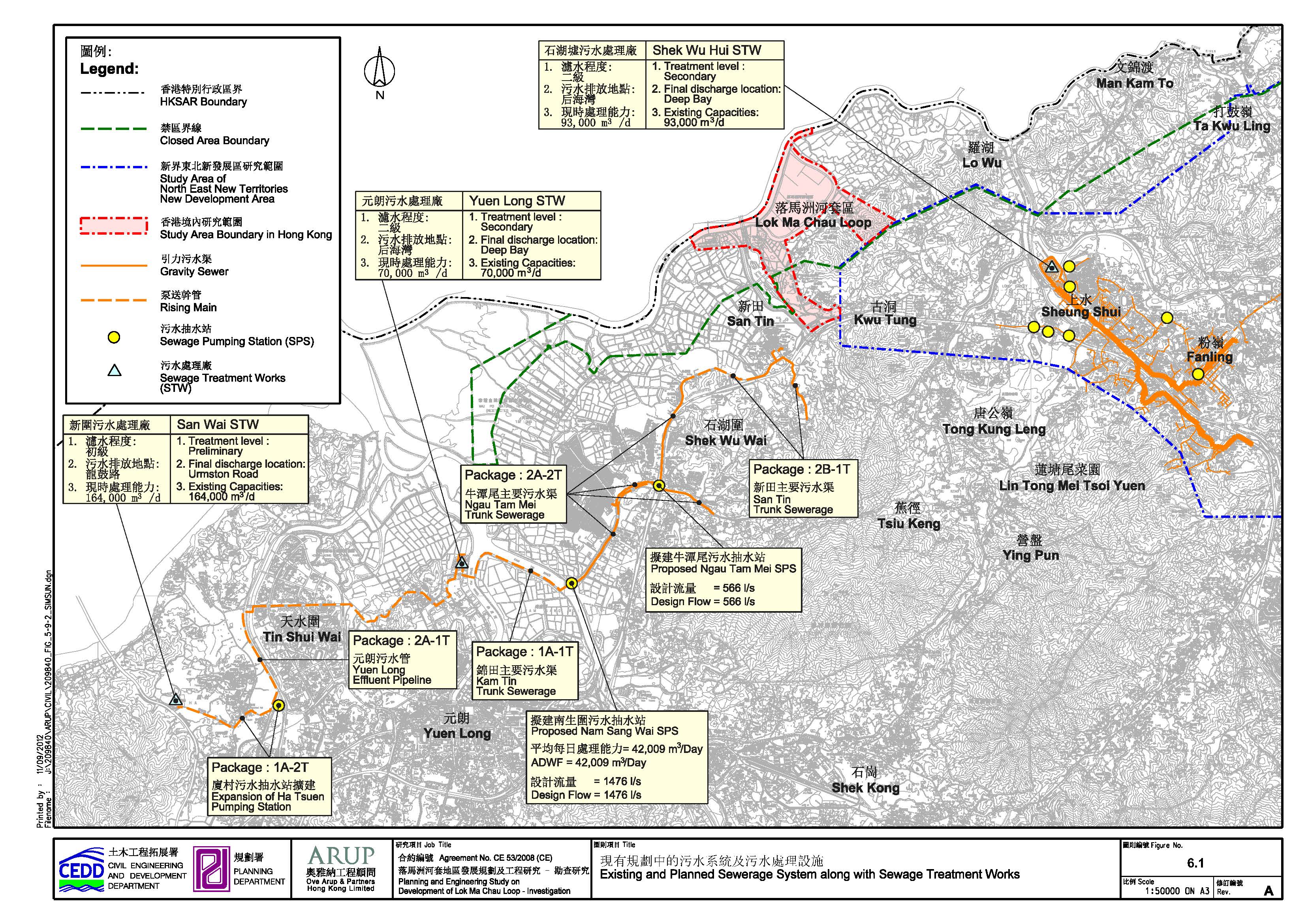
6.3.2 Existing and Planned Sewerage Infrastructures
6.3.2.1 Existing Sewage Treatment Works
The
proposed development site does not fall within sewerage catchment area (SCA) of
Shek Wu Hui STW or Yuen Long STW. The information on
existing and planned sewerage system within and in the vicinity of the Study
Area has been obtained from relevant sources and is shown in Figure
6.1.
The
following section provides a brief description of the STWs associated with the
study.
Shek Wu Hui STW (SWHSTW)
SWHSTW
is a secondary treatment works which collects and provides treatment to the
waste water generated from Fanling/Sheung Shui and other areas
before discharging into Deep Bay through Ng Tung River and SZ River. The capacity of the SWHSTW is being upgraded
under the Project PWP Item 4229DS/A entitled
“Expansion of Shek Wu Hui Sewage Treatment Works and
Ting Kok Road Pumping Station No. 5” (the
Project). The project is an interim
expansion as recommended in Agreement No. CE28/99 entitled “Review of North
District and Tolo Harbour Sewerage Master
Plans”. The construction works of the
SWHSTW expansion commenced in September 2005 and has been completed in February
2009. The scope of the project includes
increasing the treatment capacity of SWHSTW from 80,000m3/day to
93,000m3/day so as to cater for the base growth of population in Sheung Shui/Fanling
areas up to year 2011 and extension of public sewerage to nearby villages.
However, the above interim expansion does not take into consideration the
additional sewage generated from the proposed development. Therefore, further
expansion and upgrading of the SWHSTW would be required, if it is preferred to
convey the sewage treatment to SWHSTW for treatment and disposal.
Yuen Long STW (YLSTW)
Alternatively,
the sewage generated from proposed development site can be conveyed to Yuen
Long STW. However, this option would require substantial upgrading of Ngau Tam Mei/San Tin Trunk Sewerage. Although, YLSTW does
not reserve any capacity for the sewage flows from this project, it has some
spare capacity based on design capacity of YLSTW as 70,000m3/d and
projected flow of 46,000m3/day as per findings under Planning and
Development Study in North West New Territories. However, due to recent
proposal of effluent polishing at YLSTW, the capacity has been reduced to
46,000m3/day.
6.3.2.2 Existing and Planned Sewerage Systems
Under
the present condition, there is no public sewerage system in the vicinity of
proposed development site except for the Sewage Treatment Plant (STP) within
LMC Terminus. The nearest sewerage system would be Ngau
Tam Mei/San Tin Trunk Sewerage which is currently in design stage. However, the
Ngau Tam Mei/San Tin Trunk Sewerage does not cater
for additional flows from the proposed development.
Figure 6.1 shows the existing and planned sewerage system in relation to the proposed development for further investigation during the course of the study. The current effluent discharge standards for SWHSTW and YLSTW are summarised in Table 6.1 below.
Table 6.1 Current
effluent discharge standards for SWHSTW and YLSTW
|
Parameter |
SWHSTW |
YLSTW |
|
BOD5
(mg/L) |
20 (95%-ile) / 40 (upper limit) |
20 (95%-ile) / 40 (upper limit) |
|
TSS (mg/L) |
30 (95%-ile) / 60 (upper limit) |
30 (95%-ile) / 60 (upper limit) |
|
NH3-N
(mg/L) |
2 (95%-ile) / 4 (upper limit) |
Not specified |
|
NO3-N
(mg/L) |
12 (95%-ile) / 24 (upper limit) |
Not specified |
|
E. coli (cfu/100mL) |
1,500 (95%-ile) / 100 (monthly geometric mean) |
Not specified |
The assessment of sewerage and sewage treatment implications is referred to Section 6.5 in Annex 14 of the TM-EIAO. Hydraulic assessment was conducted based on Part 1 of Sewerage Manual of DSD. Capacity consideration for the future population from LMC Loop and the design parameters were based on EPD’s GESF.
6.4.1 Development Parameters
Based on the RODP, the proposed
LMC Loop development site will have approximately 24,000 students and 29,370
staff. The breakdown of
population/employment data are shown on Table
6.2. Approximately 12,000 students
will be residing at Campus. Based on
current planning proposals, approximately 1,200,000m2 total GFA is
proposed for the LMC Loop development and around 1.5% of the total GFA is
assigned for Canteens. By assuming 25% of the GFA for Canteens for Kitchen
purpose, the area of Kitchen is about 4,500m2.
Table
6.2 Population and
employment data for the LMC Loop
|
Land Use |
Maximum Number of Students |
Employment Opportunities |
|
Higher
Education |
24,000 (12,000
resident + 12,000 non-resident) |
6,000 |
|
High-tech
R&D / C&C Industries |
N/A |
22,094 |
|
Supporting
Commercial |
N/A |
1126 |
|
Government
Uses |
N/A |
150 |
|
Total |
24,000 |
29,370 |
A unit flow factor (UFF) of 0.04m3/person/day comprising 0.025m3/person/day for flushing and 0.015m3/person/day for fresh water is used for sewage flows estimation for students according to Table T-2 of EPD’s GESF. Similarly a unit flow factor (UFF) of 0.28m3/person/day comprising 0.05m3/person/day for flushing and 0.23m3/person/day for fresh water is used for sewage flows estimation for staff and their associated activities. To estimate the sewage flows from students and staff residences, it is assumed that sewage flow will resemble Institutional and special class category in Table T-1 of EPD’s GESF. A UFF of 0.19m3/person/day is used for sewage flows estimation from residences. Whereas, a UFF as 0.5m3/m2 Kitchen Area/day is used to estimate the sewage flow generated from Kitchen areas.
6.4.3 Catchment Inflow Factors
The Catchment Inflow Factors (Pcif) cater for the net overall ingress of water or wastewater to the sewerage system. They are catchment-dependent and applicable to major sewerage facilities of a catchment. They are not applicable to new catchments which are deemed to be free from misconnections and pipe defects. Therefore, the Pcif are not applicable in estimating the total flows from the new development areas.
Peaking factors cater for seasonal/diurnal
fluctuation and normal amount of infiltration and inflow. The peaking factors
shall be in accordance with EPD’s GESF and are shown in Table 6.3.
Under normal condition, peaking factors
(excluding stormwater allowance) are applicable to
planning sewerage facilities receiving flow from new upstream sewerage systems
which essentially have no misconnections and defects for infiltration. If the
service conditions of the upstream sewerage systems for the planning horizons
under consideration are unclear, peaking factors (including stormwater
allowance) shall be used. For design purpose, the peaking factors (including stormwater allowance) will be adopted.
Table
6.3 Peaking factors for various population ranges
|
Population Range |
Peaking Factor (including stormwater allowance) for facility with existing
upstream sewerage |
Peaking Factor (excluding stormwater allowance) for facility with new upstream
sewerage |
|
Sewers |
||
|
<
1,000 |
8 |
6 |
|
1,000
– 5,000 |
6 |
5 |
|
5,000
– 10,000 |
5 |
4 |
|
10,000
– 50,000 |
4 |
3 |
|
>
50,000 |
Max
(7.3/N0.15, 2.4) |
Max
(6/N0.175, 1.6) |
|
Sewage Treatment Works, Preliminary
Treatment Works and Pumping Stations |
||
|
<
10,000 |
4 |
3 |
|
10,000
– 25,000 |
3.5 |
2.5 |
|
25,000
– 50,000 |
3 |
2 |
|
>
50,000 |
Max
(3.9/N0.065, 2.4) |
Max
(2.6/N0.065, 1.6) |
Note:
N = Contributing
population in thousands.
The global unit load factors used to estimate
the sewage loading from the proposed developments are used as referred in Table
4 of the Sewerage Manual Part 1 (SM1) and are listed in Table 6.4 below.
Table 6.4 Summary of
adopted unit load factors
|
Trades |
Unit |
SS (kg/d) |
BOD (kg/d) |
COD (kg/d) |
TKN (kg/d) |
NH3-N (kg/d) |
E. coli (no./d) |
|
Domestic (Residential) |
Person |
0.04 |
0.042 |
0.09 |
8.5x10⁻³ |
5 x10⁻³ |
4.3x10¹⁰ |
|
Commercial[1] |
Employee |
0.059 |
0.087 |
0.173 |
9.2x10⁻³ |
4.8 x10⁻³ |
3.5x10¹⁰ |
|
Schools[2] |
Person |
0.034 |
0.034 |
0.07 |
6.7x10⁻³ |
4 x10⁻³ |
3.5x10¹⁰ |
Notes:
[1] Unit Load Factors (Commercial) is the sum of Unit Load
Factors for commercial activities and employed population.
[2] Unit Load Factors of Schools is the Unit Load Factor of
employed population.
Pipe
hydraulics is based on Colebrook-White Equation with ks
= 1.5mm for concrete pipe and v = 0.000001 m²/s according to Table 5, DSD's
SM1.
6.4.7.1 Land Use Planning for the Closed Area – Feasibility Study
According
to the planning study for the Frontier Closed Area, with the opening of the
Closed Area, it was proposed to expand the boundaries of the relevant
recognized villages in order to cater for the 10-year Small House demand
forecast for these recognized villages. An integrated approach needs to be
adopted for the collection, treatment and disposal of sewage from these
developments.
The proposed North East New Territories New Development
Areas (NDAs) Study is on-going. Based upon the
planning proposals for NDAs development, SWHSTW cannot handle the additional
sewage flows from NDAs and therefore expansion of SWHSTW is required.
Furthermore, SWHSTW needs to be upgraded to cater for additional loading
generated by other developments within its sewage catchment area.
One of the sewage treatment and
disposal options for LMC Loop is to convey the sewage flows to SWHSTW for
treatment and disposal. Therefore, allowance was made in the proposed expansion
and upgrading of SWHSTW under NDAs Study.
6.5 Identification and Evaluation of Sewage and Sewerage Treatment Implications
Based upon the proposed
development parameters for LMC Loop, a total Average Dry Weather Flow (ADWF) estimate
from the LMC Loop would be approximately 14,689m3/day with detailed
calculation provided in Appendix 6-1.
Based on the above assumptions,
the proposed sewage treatment works (STW) shall be designed with Average Dry
Weather Flow (ADWF) of approximately 18,000m3/day to suit the
development parameters.
The projected flow would result in an equivalent population of approximately 55,560 and therefore STW shall be designed with a peaking factor of 2.40 with stormwater allowance.
6.5.2 Pollutant Load Estimation
The unit load factors used to estimate the pollutant loading are
categorised by Domestic, Commercial and School (see Table 6.4)
For calculation of loading due to Domestic, the combined population of 13,145 has been assumed, made up of 12,000 residing students within the Loop campus and about 1,145 people residing at the nearby Lok Ma Chau village.
For calculation of loading due to School, the total number of students and staff in High Education has been assumed.
For loading due to Commercial, the C&C Industries, Hi-tech R&D,
Supporting Commercial and Government Uses are grouped into this category.
For estimation of loading from Kitchen, SS and BOD loading of 300 g/m2 kitchen area/day has been assumed in accordance with Appendix 3 of “Guidelines for the Design of Small Sewage Treatment Plant” from EPD.
Based on the above, the development parameters (see
Chapter 2) and the load factors in Table 6.4, the pollutant loads are
estimated and shown on Table 6.5.
Table
6.5 Projected pollutant loads
|
Load |
SS (kg/d) |
BOD (kg/d) |
COD (kg/d) |
TKN (kg/d) |
NH3-N (kg/d) |
E.
coli (no./d) |
|
Residential |
525.8 |
552.1 |
1,183.1 |
111.7 |
65.7 |
5.65x10¹⁴ |
|
High
Education |
612.0 |
612.0 |
1260.0 |
120.6 |
72.0 |
6.30x10¹⁴ |
|
Hi-tech
R&D / C&C Industries |
1212.5 |
1787.9 |
3555.2 |
189.1 |
98.6 |
7.19x10¹⁴ |
|
Supporting
Commercial |
157.5 |
232.3 |
461.9 |
24.6 |
12.8 |
9.35x10¹³ |
|
Kitchen
(Area 4,500m2) |
1350.0 |
1350.0 |
- |
- |
- |
- |
|
Government
Uses |
8.9 |
13.1 |
26.0 |
1.4 |
0.7 |
5.25x10¹² |
|
Total |
3866.7 |
4547.4 |
6486.2 |
447.4 |
249.8 |
2.01x10¹⁵ |
With the total projected flow of
18,000m3/day and the projected pollutant loads as shown in Table 6.5, the average sewage
concentration is estimated and shown on Table
6.6.
Table 6.6 Projected
pollutant concentrations
|
SS (mg/L) |
BOD (mg/L) |
COD (mg/L) |
TKN (mg/L) |
NH3-N (mg/L) |
E. coli
(no./100ml) |
|
214.8 |
252.6 |
360.3 |
24.9 |
13.9 |
1.12x10⁷ |
LMC Loop is located within the
Deep Bay Water Control Zone (WCZ). Since the treated sewage effluent generated
from the development site, if discharged directly or in-directly to the Deep
Bay, is required to comply with ‘No net increase in pollution load’ Policy,
compensation measures should be taken.
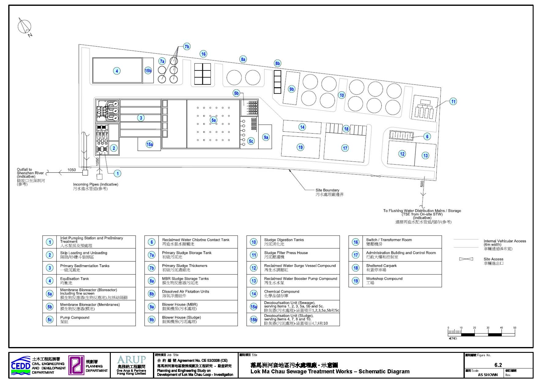
A new sewerage network will be
required to convey sewage flow from various lots within the LMC Loop to the
proposed on-site STW for its treatment and disposal. Figure 6.2 shows the
preliminary layout of the proposed sewerage system for the LMC Loop. The
majority of alignment of the proposed trunk sewerage network is either along
the proposed roads or through amenities area. The drainage reserve will be
required to lay the sewer pipe outside the roads such as through amenities
areas or open spaces. The hydraulic calculation of the sewerage system is
presented in Appendix 6-1.
The development will be
constructed in phases to support the first intake of population targeted in
2020 (see Chapter 2). In order to
support the first population in-take, the construction of the new on-site
sewage treatment works and the new trunk sewers will need to be completed prior
to first population intake. The construction of sewerage system will be carried
out as part of site formation works.
6.6.1 On-site Sewage Treatment Works
6.6.1.1 Compliance to “No Net Increase in Pollution Load”
In order to comply with ‘No net
increase in pollution loads’ policy, the sewage from LMC Loop development shall
be treated to a very high standard, together with the pollutant loads reduction
measures in the northern districts including the planned NENT NDAs and SWHSTW.
As estimated, there will be
18,000m3/day of sewage flow to be treated in the proposed onsite
STW. With the proposed discharge standard of LMC Loop STW as shown in Table 6.7, the residual pollution loads
of the STW effluent without compensation have been estimated and shown in Table 6.8.
Table
6.7 Discharge
standards for on-site STW
|
Parameter |
Unit |
Value for design (proposed to be adopted as
95%-ile under licence
conditions) |
Proposed Upper Limit under licence conditions |
Standards for effluents discharged into
Group B inland waters (for reference) |
|
Average flow |
m3/day |
18,000 |
- |
- |
|
BOD5 |
mg/L |
5 |
10 |
20 |
|
TN |
mg/L |
8 |
16 |
- |
|
TP |
mg/L |
1 |
2 |
5 |
|
TSS |
mg/L |
10 |
20 |
30 |
|
NH3-N |
mg/L |
1.9 |
3.8 |
5 |
|
E.coli |
cfu/100mL |
1,500 |
100 (monthly
geometric mean) |
100 |
Note: All the proposed discharge standards
are set as 95th-percentile except that for E. Coli as geometric mean. cfu = colony-forming unit. The
maximum range of flow rate of 2,000-3,000m3/day extracted from Table
4 of “Technical Memorandum - Standards for Effluents Discharged into Drainage
and Sewerage Systems, Inland and Coastal Waters” for reference purpose.
Table 6.8 Pollutant loads
discharge subject
to ”no net increase in pollution loads”
|
Parameter |
Unit |
Average Flow = 18,000 m3/day |
|
BOD5 |
kg/day |
90 |
|
TN |
kg/day |
144 |
|
TP |
kg/day |
18 |
It should be noted that a pre-requisite for
achieving “No net increase in pollution loads” for the LMC Loop development is
to implement pollutant load reduction measures in the northern districts, such
that the pollutant load given in Table
6.8 above is covered. The compensation will be covered by upgrading of
SWHSTW, which will be under the NENT NDAs study (see Chapter 2) and will be initiated by CEDD.
There will be additional buffer
for pollutant load being discharged to Deep Bay when Treated Sewage Effluent
(TSE) reuse is pursued. The minor relaxation of discharge standard could
possibly be achieved or additional treatment capacity could be provided to
other surrounding users. For design purpose, however, the proposed discharge
standards and projected effluent flow given in Table 6.7 shall be referenced as the basis.
As worst scenario consideration,
TSE reuse is not included in calculations for compliance with “No net increase
in pollution load” and the calculation are presented
in Appendix 6-2.
In considering similar treatment method and domestic influent characteristics for both LMC on-site STW and SHWSTW, the effluent component in various parameters would be comparable. Given that the 3 parameters, BOD5, TN and TP, have been shown to comply with the “No net increase in pollution load” policy, the same compliance can be expected of the other parameters such as SS and E.coli. In addition, SS and E.coli will not contribute algal bloom and will be reduced by settling and degrading. Adverse impact on the receiving water bodies (i.e. Shenzhen River) for SS and E.coli is not anticipated. Further review on the loading of BOD5, TN (or ammonia), TP, SS and E.coli according to field data, assimilation capacity and water quality needs of the receiving water body is recommended during the detailed design stage of the proposed LMC Loop STW.
6.6.1.2 Sewage Treatment Strategies
Under the
current study stage, Membrane Bio-Reactor (MBR) system has been considered for
the LMC Loop STW due to the very stringent discharge requirement. Compared to Conventional
Activated Sludge Process with a Biological Effluent Filter for nitrogen
removal, MBR system does not require large footprint as it can be operated under high mixed
liquor suspended solids (MLSS) concentration, typically 8,000mg/L but could go up
to as high as 15,000mg/L. In addition, membrane is used for the liquid-solid
separation so no clarifier is required, which also saves plant footprint. MBR
system is able to produce high quality effluent, which is suitable for
non-potable reuse, such as toilet flushing, irrigation etc. Therefore, MBR
system is proposed as the biological treatment process with the effluent re-use
scheme adopted. Table 6.9 presents
the attributes of MBR system for on-site STW.
Table 6.9 Attributes of MBR
|
Attribute |
MBR |
|
Overall hydraulic retention time |
12-14 hrs |
|
BOD5 removal |
95-98% (norm of MBR performance) |
|
Faecal coliform
log removal |
6-7 |
|
Area requirement |
0.08 ha per 1,000m3/day
capacity |
A sewerage network will be required to convey
sewage flow from various lots within the LMC Loop. A draft sewerage master plan
is given in Appendix 6-3.
6.6.2 Treated Sewage Effluent Reuse
Treated Sewage Effluent (TSE) reuse has the advantage of reducing wastewater
discharge in the receiving waterbodies thereby reducing
the pollution load to the environment. It also reduces demand on raw water,
which is a scarce natural resource deserved for preservation to the maximum
extent practicable.
TSE reuse is proposed for LMC Loop
development as a result of a number of opportunities listed below:
No net increase in pollution loads
to Deep Bay
· The additional pollutant loading within the sewage catchment will have to be compensated via a higher level of sewage treatment prior to discharge. More stringent TSE discharge requirement will be necessary. Under this setting, the quality of TSE for discharge is indeed equivalent to, if not far away from, TSE reuse for non-potable uses.
Non-saline sewage/effluent
· Unlike coastal areas, the northern district is not supplied with salt water for flushing due to the fact that extensive and long-distance pumping of salt water from Sha Tau Kok area to LMC Loop is not economical. In other words, the sewage or TSE will mainly be non-saline which may be suitable for higher grade non-potable reuse eg landscape irrigation, apart from low grade non-potable reuse eg toilet flushing.
Cost-effectiveness
· As mentioned above, since TSE discharge standard is very high for LMC Loop, further purification of TSE satisfying reuse standard would not be prohibitively high. In addition, the energy associated with distribution of TSE reuse within the 87 hectares of LMC Loop will minimise the pumping energy during the operation. Further, TSE reuse substitutes the alternative fresh water supply for non-potable purposes, making water reuse possible and enhancing water efficiency.
Public anticipation
· TSE reuse is not a new concept in Hong Kong as there have been several earlier pilot or demonstrated schemes. This could be regarded as one of the sustainable initiatives for new development, and is also in line with the Total Water Management (TWM) initiatives of the Hong Kong SAR Government.
6.6.2.1 Applications and TSE Reuse Water Quality
The TSE is proposed to be reused
for non-potable uses such as toilet flushing, landscape irrigation and make-up
water for district cooling system (DCS). If there are reuses, the discharge
effluent from the development to the Deep Bay (and thus the pollutant load)
will be further reduced.
Since the total projected effluent
reuse quantity is lower than the total treated effluent generated from the
development area, there will always be discharges from the development area to
the Deep Bay unless effluent exportation to outside the Deep Bay WCZ is
implemented. However, sewage impacts to the Deep Bay from the development will
be reduced proportionally if part of the treated effluent is to be reused.
Therefore, the above implication assessment represents the worst case scenario
without consideration of any reuse or exportation outside the Deep Bay WCZ.
Based on the current study stage,
the amount of effluent to be reused within LMC Loop development is estimated
and presented in Table 6.10. The
proposed water quality standards of TSE reuse for various non-potable reuses
are presented in Table 6.11,
referencing the prevailing water supply guidelines, international guidelines
(e.g. USEPA) or on-going TSE reuse projects (e.g. Ngong
Ping STW) for the intended non-potable water uses, balancing with practicality
and anticipated end-user satisfaction. One of the benefits of adopting a
universal TSE reuse quality is to standardise such that additional distribution
pipeline or conveyance system is not required.
Table 6.10 Estimated
quantities of TSE reuse
|
Reuse of Effluent |
Quantity (m3/day) |
|
Toilet Flushing |
3,510 |
|
Irrigation (Including Ecological Area) |
1,950 |
|
District Cooling System[Note] |
5,000 |
|
Total
|
10,460 |
Note: DCS is a closed circuit system. The
water demand for DCS refers to the replenishment of water from cooling tower
due to evaporation, drift and bleed-off. The 5000m3/day water demand
represents the average replenishment rate for DSC by TSE reuse.
Table 6.11 Proposed water quality standards of TSE reuse
|
Water
Quality Parameter |
Unit |
Recommended
Standard for Flushing, Landscape Irrigation and DCS Make-up |
|
E.
Coli |
cfu/100mL |
Not detectable |
|
Total residual chlorine (TRC) |
mg/L |
>1 (out of treatment system) >0.2 (at point-of-use) |
|
Dissolved oxygen (DO) |
mg/L |
>2 |
|
TSS |
mg/L |
<5 |
|
Colour |
HU |
<20 |
|
Turbidity |
NTU |
<5 |
|
pH |
- |
6 – 9 |
|
Threshold odour number (TON) |
TON |
<100 |
|
BOD5 |
mg/L |
< 10 |
|
Ammonia nitrogen |
mg/L |
<1 |
|
Synthetic detergents |
mg/L |
<5 |
Note: Apart from TRC which has been specified, the
water quality standards for all parameters shall be applied at the point-of-use
of the system. HU = Hazen Unit. NTU = Nephelometric
Turbidity Unit.
Facilities for TSE reuse
will involve the flushing water service reservoir. The area of water service
reservoir will be about 2 ha. The major construction works will include
earthwork, slopework (including soil nailing and
retaining walls), concrete works for service reservoir structure and
construction of maintenance road near the ECR.
6.6.2.2 Public Health Implication
In general,
the following precautionary measures should be adopted for TSE reuse:
· To avoid cross connection and hence contamination, all pipes and fittings used for the TSE water supply and distribution system should be purple in colour for distinguishing them from the pipes and fittings used for the fresh water supply and distribution systems.
· Regular checking/inspections of the TSE supply and distribution systems for possible cross connection to the fresh water supply and distribution system should be carried out. The use of non-toxic dye may be adopted in the checking/inspections.
· Warning signs should be permanently displayed where public access to TSE is possible (except for toilets) notifying the employees, visitors and the public at large that treated effluent is being used and is not suitable for drinking.
· Storage of sodium hypochlorite solution will be required and this is not a hazardous material. Thus, the storage is not considered as Potentially Hazardous Installation (PHI).
The usual
practice to distinguish reclaimed water pipe work from potable pipework is by colour code. Under Demonstration Scheme on
Reclaimed Water Uses in the Northern District, for example, purple/lavender
coloured pipes were used between SWHSTW to respective user’s premises for easy
differentiation from existing pipework.
Apart from
that, proper signage, promotion and education to the general public especially
potential local users of reclaimed water for landscape irrigation shall be
considered and implemented.
The main
health concern with TSE reuse is the small but definite risk of diarrhoeal
diseases associated with accidental ingestion of insufficiently treated TSE.
With the implementation of precautionary measures set out in above, and the
adoption of stringent health-based water quality standards for the TSE,
significant increase in health risk is not expected.
Under the present condition, there is
no public sewerage system in the vicinity of proposed development site. The proposed LMC Loop development
will generate additional sewage flows and loads which cannot be handled by the
existing YLSTW or SWHSTW. In order to meet the prevailing
water quality policies of “No net increase in pollution load”, treatment
facility will be required for the generated sewage from LMC Loop development.
On-site STW and off-site load compensation at SWHSTW is recommended. In addition, MBR is recommended as the sewage treatment process to be adopted in the on-site STW, which requires smaller footprint and generates effluent quality readily for TSE reuse purpose. In order to meet “No net increase in pollution load” in Deep Bay upgrading of SWHSTW is recommended to compensate for the residual loads and the proposal is recommended to be taken into consideration in the ongoing Study for expansion/upgrading of SWHSTW.