The EIA Report has assessed the water quality impacts associated with the Project. According to the EIA Report, the water quality impact could be minimized with the implementation of mitigation measures. The water quality monitoring programme as discussed below could ensure the implementation of the recommended mitigation measures and provide continue improvements to the environmental conditions.
The EIA Report has recommended good site practices as the construction phase mitigation measures. All the proposed mitigation measures are summarized in the Project Implementation Schedule (PIS) in Appendix 2-2.
Water quality monitoring at the Meander and Shenzhen River is required. The monitoring at the Meander should be conducted during construction of WCR bridge pier and ECR underpass, whereas the monitoring at Shenzhen River should be conducted during entire construction period and bio-remediation.
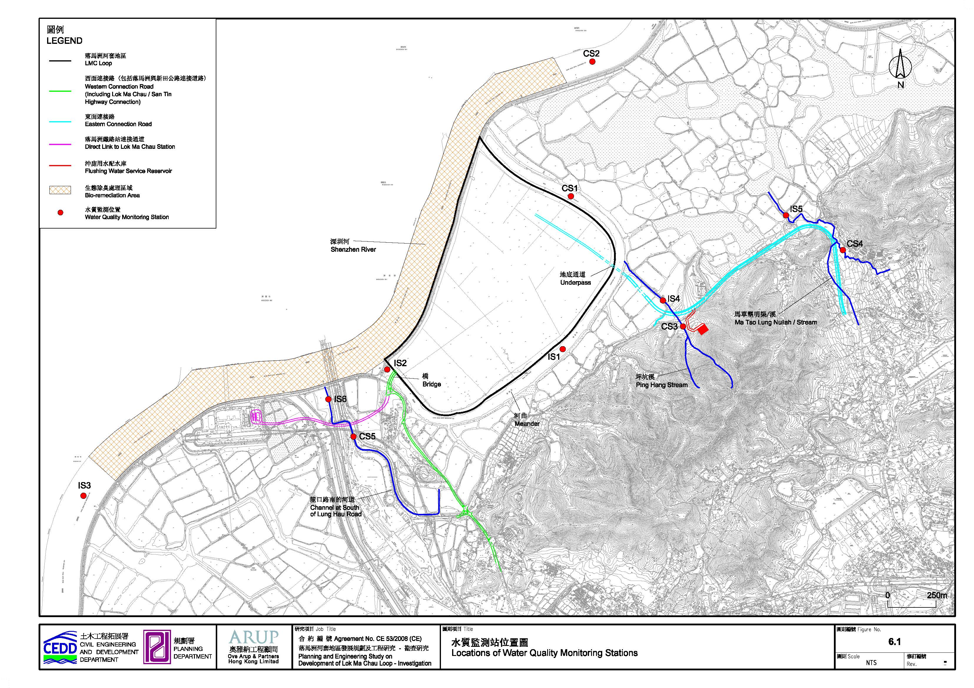
The water quality monitoring stations and control stations were selected based on downstream and upstream of impacted area and are shown in Figure 6.1. Details of sensitive receivers could refer to the EIA report. For easy reference, the sensitive receiver locations are attached in Appendix 6.1. The proposed locations are classified as Impact Station and Control Station according to their functions and tidal conditions. The ET shall seek approval from IEC and EPD for any alternative monitoring locations. The IEC/EPD/Engineer’s Representative may also request a closer locations based on on-site conditions and environmental complaint.
Measurements shall be taken at 3 water depths, namely, 1m below water surface, mid-depth and 1m above river bed, except where the water depth less than 6m, the mid-depth measurement may be omitted. Should the water depth be less than 3m, only the mid-depth measurement will be taken.
Table
6.1 Water Quality Monitoring Stations for Baseline and
Construction Phase Monitoring
|
Station |
Description |
Locations |
Measurement
Periods |
|
Meander |
|||
|
CS1 |
Control Station at Meander |
Centreline of Meander, 500m upstream of ECR
underpass |
·
Entire construction period for WCR until
first 12 months after construction ·
Entire construction period for WCR until
first 12 months after construction |
|
IS1 |
Impact Station for ECR underpass construction |
Centreline of Meander, 500m downstream of ECR |
·
Entire construction period for ECR until
first 12 months after construction |
|
IS2 |
Impact Station for ECR underpass construction and
WCR bridge construction |
Centreline of Meander at Bridge of Boundary
Patrol Road, downstream of WCR |
·
Entire construction period for WCR until
first 12 months after construction |
|
Shenzhen River |
|||
|
CS2 |
Control Station at Shenzhen River (Ebb tide) Impact Station at Shenzhen River (Flood tide) |
Centreline of Shenzhen River (Hong Kong side),
500m upstream of Bio-remediation |
·
Entire construction period until first
12 months after construction ·
Every bio-remediation until first 12
months after construction |
|
IS3 |
Impact Station for Bio-remediation (Ebb tide) Control Station at Shenzhen River (Flood tide) |
Centreline of Shenzhen River (Hong Kong side),
downstream of Bio-remediation |
·
Entire construction period until first
12 months after construction ·
Every bio-remediation until first 12
months after construction |
|
Ping Hang Stream |
|||
|
CS3 |
Control Station at Ping Hang Stream |
Centreline of Ping Hang Stream, upstream of
viaduct works of ECR |
·
Entire construction period for ECR until
first 12 months after construction |
|
IS4 |
Impact Station for ECR construction |
Centreline of Ping Hang Stream, downstream of
viaduct works of ECR |
·
Entire construction period for ECR until
first 12 months after construction |
|
Ma Tso Lung
Nullah/Stream |
|||
|
CS4 |
Control Station at Ma Tso Lung Nullah/Stream |
Centreline of Ma Tso Lung Nullah/Stream, upstream
of viaduct works of ECR |
·
Entire construction period for ECR until
first 12 months after construction |
|
IS5 |
Impact Station for ECR construction |
Centreline of Ma Tso Lung Nullah/Stream,
downstream of viaduct works of ECR |
·
Entire construction period for ECR until
first 12 months after construction |
|
Channel at south
of Lung Hau Road |
|||
|
CS4 |
Control Station at channel at south of Lung Hau
Road |
Centreline of south of Lung Hau Road, upstream of
road widening works of WCR |
·
Entire construction period for WCR until
first 12 months after construction |
|
IS5 |
Impact Station for WCR construction |
Centreline of south of Lung Hau Road, downstream
of road widening works of WCR |
·
Entire construction period for WCR until
first 12 months after construction |
The monitoring shall normally be established by measuring the Dissolved Oxygen (DO), temperature, turbidity, pH and Suspended Solids (SS) at all designated locations as specified in Section 6.3 above. Monitoring of heavy metals (As, Cu, Cd, Cr, Pb, Hg, Ni, Ag and Zn) and nutrient (Ammonia N, unionised ammonia, NO3-N, NO2-N, TKN-N, TP and PO4) shall be conducted at the monitoring stations for bio-remediation (i.e. CS2 and IS3).
The measurements shall be taken at all designated monitoring stations, 3 days per week. The interval between two sampling surveys shall not be less than 36 hours.
Replicate in-situ measurements and samples collected from each independent sampling event shall be collected to ensure a robust statistically interpretable database. DO, temperature, pH and turbidity should be measured in-situ whereas SS, heavy metals and nutrients should be determined by an accredited laboratory.
Other relevant data shall also be recorded, including monitoring location / position, time, water depth, weather conditions and any special phenomena or work underway at the construction site.
Baseline conditions for water quality shall be established and agreed with IEC, ER and EPD prior to be commencement of construction works in the Meander. The purpose of the baseline monitoring is to establish ambient conditions prior to the commencement of the works and to demonstrate the suitability of the proposed impact and control monitoring stations.
The baseline mentoring shall be conducted for at least 4 weeks prior to the commencement of works. The proposed water quality monitoring schedule shall be submitted to IEC, ER and EPD by the ET at least 2 weeks before the first day of the monitoring month. The interval between two sets of monitoring shall not be less than 36 hours. IEC, ER and EPD shall also be notified immediately for any changes in schedule.
There should be no construction work in the vicinity of the stations during the baseline monitoring. According to the EIA, it is unlikely to have concurrent aquatic activities in the Meander. In case if the monitoring programme overlaps with other non-project aquatic activities, the monitoring exercise should be scheduled as far as possible to avoid concurrent activities around the monitoring stations such that representative ambient data could be sampled.
The baseline data will be used to establish the Action / Limit Levels. The determination of Action / Limit Levels will be discussed in Section 6.10.
Table 6.2 summarizes the proposed monitoring frequency and water quality parameters for baseline monitoring.
Table
6.2 Proposed water quality monitoring programme
|
|
Baseline
Monitoring |
|
Monitoring Period |
At least 4 weeks prior to the commencement of
construction for WCR pier or ECR underpass in the Meander, whichever earliest |
|
Monitoring Frequency |
3 days in a week |
|
Monitoring Locations |
All Stations |
|
Monitoring Parameters |
All Stations: DO, salinity, temperature, pH, turbidity and SS Stations for bio-remediation (CS2, IS3): As, Cu, Cd, Cr, Pb, Hg, Ni, Ag, Zn, Ammonia N,
unionised ammonia, NO3-N, NO2-N, TKN-N, TP and PO4 |
|
Intervals between 2 Sets of Monitoring |
Not less than 36 hours |
The impact monitoring shall be conducted during entire construction period. The purpose of impact monitoring is to ensure the implementation of the recommended mitigation measures, provide effective control of any malpractices, and provide continuous improvements to the environmental conditions. The proposed water quality monitoring schedule shall be submitted to IEC, ER and EPD by the ET at least 2 weeks before the first day of the monitoring month. The interval between two sets of monitoring shall not be less than 36 hours. IEC, ER and EPD shall also be notified immediately for any changes in schedule.
In case of project-related exceedances of Action and/or Limit Levels, the impact monitoring frequency shall be increased according to the requirement of Event and Action Plan. The details of Event Action Plan will be discussed in Section 6.11.
Table 6.3 summarises the proposed monitoring frequency and water quality parameters for and impact monitoring.
Table
6.3 Proposed water quality monitoring programme
|
|
Impact Monitoring |
|
Monitoring Period |
Generally during entire construction period until
first 12 months after construction Generally during every bio-remediation process
until first 12 months after construction |
|
Monitoring Frequency |
3 days in a week |
|
Monitoring Parameters |
All Stations: DO, salinity, temperature, pH, turbidity and SS Stations for bio-remediation (CS2 and IS3): As, Cu Cd, Cr, Pb, Hg, Ni, Ag, Zn, Ammonia N,
unionised ammonia, NO3-N, NO2-N, TKN-N, TP and PO4 |
|
Intervals between 2 Sets of Monitoring |
Not less than 36 hours |
The ET shall propose and implement a verification monitoring programme in light of latest stormwater drainage plan to verify the efficiency and effectiveness of silt trap and cleaning frequency of non-point source loading during rainstorm events. The verification monitoring programme, including parameters and frequencies, shall be verified by IEC and approved by EPD prior to measurement.
6.8.1 Dissolved Oxygen and Temperature Measuring Equipment
The dissolved oxygen (DO) measuring instruments should be portable and weatherproof. The equipment should also complete with cable and sensor, and DC power source. It should be capable of measuring:
· A DO level in the range of 0 – 20 mg/L and 0 – 200% saturation; and
· A temperature of 0 – 45 degree Celsius
The equipment should have a membrane electrode with automatic temperature compensation complete with a cable.
Should salinity compensation not be built-in to the DO equipment, in-situ salinity should be measured to calibrate the DO measuring instruments prior to each measurement.
6.8.2 Salinity Equipment
A portable salinometer capable of measuring salinity in the range of 0 - 40 parts per thousand (ppt) should be provided for measuring salinity of the water at each monitoring location.
6.8.3 pH Measuring Equipment
A portable pH meter capable of measuring a pH range between 0.0 and 14.0 shall be provided under the specified conditions (e.g., Orion Model 250A or an approved similar instrument).
6.8.4 Turbidity Measuring Equipment
The turbidity measuring instruments should be a portable and weatherproof with DC power source. It should have a photoelectric sensor capable of measuring turbidity level between 0 - 1000 NTU (for example, Hach model 2100P or an approved similar instrument).
6.8.5 Positioning Equipment
A hand-held or boat-fixed type digital Differential Global Positioning System (DGPS) with way point bearing indication and Radio Technical Commission for maritime (RTCM) facilities (for real-time auto-display of error messages and DGPS corrections from the Hong Kong Hydrographic Office), or other equipment instrument of similar accuracy, should be provided and used during marine water monitoring to ensure the monitoring vessel is at the correct location before taking measurements.
6.8.6 Water Depth Detector
A portable, battery-operated echo sounder should be used for water depths determination at each designated monitoring station. The detector can either be hand held or affixed to the bottom of the work boat, if the same vessel is to be used throughout the monitoring programme.
6.8.7 Water Sampler
A water sampler is required for SS monitoring. It should comprise a transparent PVC cylinder, with a capacity of not less than 2 litres, which can be effectively sealed with latex cups at both ends. The sampler should have a positive latching system to keep it open and prevent premature closure until released by a messenger when the sampler is at the selected water depth (for example, Kahlsico Water Sampler or an approved similar instrument).
6.8.8 Sample Containers and Storage
Water samples for SS determinations should be stored in high density polythene bottles with no preservative added, packed in ice (cooled to 4°C without being frozen) and shipment to the testing laboratory. The samples shall be delivered to the laboratory within 24 hours of collection and be analysed as soon as possible after collection.
6.8.9 Calibration of In-Situ Instruments
The pH meter, DO meter and turbidimeter shall be checked and calibrated before use. DO meter and turbidimeter shall be certified by a laboratory accredited under HOKLAS or any other international accreditation scheme, and subsequently re-calibrated at quarterly basis throughout all stages of the water quality monitoring. Responses of sensors and electrodes should be checked with certified standard solutions before each use. Wet bulb calibration for a DO meter shall be carried out before measurement at each monitoring station.
6.8.10 Back-up Equipment
Sufficient stocks of spare parts shall be maintained for replacements when necessary. Backup monitoring equipment shall also be made available so that monitoring can proceed uninterrupted even when some equipment is under maintenance, calibration, malfunction, etc.
A multi-probe monitoring equipment set integrated with water sampler(s) is highly recommended to improve the monitoring efficiency. Depending on the actually operation, more than one field survey vessels might be required simultaneously to ensure the monitoring are conducted within the acceptable monitoring period. The ET shall also consider the use of unattended automatic sampling/monitoring devices at fixed stations where monitoring are required throughout the construction for WCR piers and ECR underpass in the Meander. The use of such unattended automatic devices, however, shall be subject to the approval of the ER, IEC and EPD.
6.9 Laboratory Measurement / Analysis
At least 2 replicate samples from each independent sampling event are required for the suspended solids, heavy metals and nutrients measurement which shall be carried in a HOKLAS or international accredited laboratory. Sufficient water samples shall be collected at the monitoring stations for carrying out the laboratory measurement and analysis. The laboratory determination work shall start within 24 hours after collection of the water samples. The analysis for SS, heavy metals and nutrients is presented in Table 6.4.
Table
6.4 Laboratory analysis for SS, heavy metals and
nutrients
|
Parameters |
Instrument |
Analytical Method |
Reporting Limit |
|
Suspended Solid (SS) |
Weighting |
APHA 2540-D |
0.1 mg/L |
|
Heavy Metals |
|
|
|
|
Arsenic (As) |
ICP-MS |
USEPA 6020A |
10 µg/L |
|
Cadmium (Cd) |
ICP-MS |
USEPA 6020A |
0.2 µg/L |
|
Chromium (Cr) |
ICP-MS |
USEPA 6020A |
1 µg/L |
|
Copper (Cu) |
ICP-MS |
USEPA 6020A |
1 µg/L |
|
Mercury (Hg) |
ICP-MS |
USEPA 6020A |
0.1 µg/L |
|
Nickel (Ni) |
ICP-MS |
USEPA 6020A |
1 µg/L |
|
Lead (Pb) |
ICP-MS |
USEPA 6020A |
1 µg/L |
|
Silver (Ag) |
ICP-MS |
USEPA 6020A |
1 µg/L |
|
Zinc (Zn) |
ICP-MS |
USEPA 6020A |
4 µg/L |
|
Nutrient |
|
|
|
|
Ammonia as N |
FIA |
APHA 4500-NH3 H |
0.025 mg/L |
|
Unionised ammonia |
By calculation |
By calculation |
By calculation |
|
Nitrate as N |
FIA |
APHA 4500-NO3 l |
0.025 mg/L |
|
Nitrite as N |
FIA |
APHA 4500-NO2 l |
0.025 mg/L |
|
TKN as N |
Titration |
APHA 4500-Norg+NH3H |
1 mg/L |
|
Total Phosphorus |
Colorimetric |
APHA 4500-P B&E |
0.1 mg/L |
|
Orthophosphate |
FIA |
APHA 4500-P G |
0.1 mg/L |
6.10.1 Field Logs
Field logs shall be maintained for all monitoring work, noting the date, equipment, monitoring manager and the record of all construction related activities and observations. The field log records shall be retained for the duration of the entire project and archived on completion.
In-situ monitoring results shall be digitally recorded from the instruments and converted into spreadsheet format or manually noted. Both hard and soft copies shall be retained for file records. Any deviation from the standard procedure and the reasons for deviation shall be noted in the log.
6.10.2 Measurement Procedures
All in-situ monitoring instruments shall be checked, calibrated and certified and subsequently re-calibrated at three monthly intervals throughout all stages of the water quality monitoring, or as required by the manufactures specification. Certificate(s) of Calibration specifying the instrument shall be attached to the monitoring reports.
6.10.3 Sampling
The ET/Contractor will record all data from in situ testing and from any analysis carried out in a Field Log. All samples will be identified with a unique date/time/location/depth/sample-type code which will be attached to the sample container or written in indelible ink directly on the container. In order to avoid contamination of the samples, all containers will be new and unused and of analytical grade quality. Sources of contamination will be isolated from the working area and any sample contaminated by local material will be discarded and the sampling repeated.
6.10.4 Transport of Samples
All samples transferred from one sub-contractor to another will be accompanied by Chain of Custody (COC) forms. Any missing or damaged samples require notification to ET Leader following logging in the laboratory QA system. The number of samples, the parameters to be tested and the time of delivery should be clearly stated on the COC forms to ensure that samples are analysed for the correct parameters and suitable time is provided to the analytical laboratory for provision of resources required in the analyses.
The Action and Limit Levels for water quality are defined in Table 6.5.
Table
6.5 Action and Limit levels for water quality
|
Parameters |
Action Level |
Limit Level |
|
DO in mg/L (depth average) [2] |
5 percentile of baseline data. [3] |
4 mg/L or 1 percentile of baseline data. [3] |
|
SS in mg/L (depth averaged) [2] |
95 percentile of baseline data or 120% of upstream control station. [4] |
20 mg/L or 99 percentile of baseline data or 130%
of upstream control station. [4] |
|
Turbidity in NTU (depth averaged) [2] |
95 percentile of baseline data or 120% of upstream control station. [4] |
99 percentile of baseline data or 130% of upstream control station. [4] |
|
Heavy metals in µg/L (depth averaged) [2] |
95 percentile of baseline data or 120% of upstream control station. [4] |
As: 50 µg/L[1] Cd: 5 µg/L[1] Cr: 50 µg/L[1] Cu: 1000 µg/L[1] Hg: 0.1 µg/L[1] Ni: 99 percentile of baseline data or 130% of
upstream control station[4] Pb: 50 µg/L[1] Ag: 99 percentile of baseline data or 130% of
upstream control station[4] Zn: 1000 µg/L[1] |
|
Unionized ammonia in mg/L (depth averaged) [2] |
95 percentile of baseline data or 120% of upstream control station. [4] |
0.021mg/L or 99 percentile of baseline data or
130% of upstream control station. [4] |
|
Nitrate nitrogen in mg/L (depth averaged) [2] |
95 percentile of baseline data or 120% of upstream control station. [4] |
99 percentile of baseline data or 130% of
upstream control station. [4] |
|
Orthophosphate in mg/L (depth averaged) [2] |
95 percentile of baseline data or 120% of upstream control station. [4] |
99 percentile of baseline data or 130% of
upstream control station. [4] |
[1] There
is no local criterion for heavy metals. Limit Level of heavy metals is adopted
from Category III Surface Water Quality Standards (GB3838-2002) (地表水環境質量標準), which is applicable for Shenzhen River
on mainland side
[2] “Depth-averaged”
is calculated by taking the arithmetic mean of reading of all three depths.
[3] For
DO, non-compliance occurs when monitoring results is lower than the limits.
[4] For SS,
turbidity, heavy metals, unionized ammonia, nitrate nitrogen and total
phosphorus, non-compliance occurs when monitoring results is larger than the
limits.
Should non-compliance of the criteria occur,
action in accordance with the Action Plan in the Table 6.6 shall be carried out.
Table 6.6 Event
/ Action Plan for water quality
|
Event |
Action |
|||
|
ET |
IEC |
ER |
Contractor |
|
|
Action level being exceeded by one sampling day |
1. Inform IEC, Contractor and ER; 2. Check monitoring data, all plant,
equipment and Contractor’s working methods; and 3. Discuss remedial measures with IEC and
Contractor and ER. |
1. Discuss with ET, ER and Contractor on
the implemented mitigation measures; 2. Review proposals on remedial measures
submitted by Contractor and advise the ER accordingly; and 3. Review and advise the ET and ER on the
effectiveness of the implemented mitigation measures. |
1. Discuss with IEC, ET and Contractor on
the implemented mitigation measures; 2. Make agreement on the remedial
measures to be implemented; 3. Supervise the implementat-ion
of agreed remedial measures. |
1. Identify source(s) of impact; 2. Inform the ER and confirm notification
of the non-compliance in writing; 3. Rectify unacceptable practice; 4.Check all plant and equipment; 5. Consider changes of working methods; 6. Discuss with ER, ET and IEC and
purpose remedial measures to IEC and ER; and 7. Implement the agreed mitigation
measures. |
|
Action level being exceeded by more than one consecutive
sampling days |
1. Repeat in-situ measurement on next day
of exceedance to confirm findings; 2. Inform IEC, contractor and ER; 3. Check monitoring data, all plant,
equipment and Contractor’s working methods; 4. Discuss remedial measures with IEC, contractor
and ER 5. Ensure remedial measures are
implemented |
1. Discuss with ET, Contractor and ER on
the implemented mitigation measures; 2. Review the proposed remedial measures
submitted by Contractor and advise the ER accordingly; and 3. Review and advise the ET and ER on the
effectiveness of the implemented mitigation measures. |
1. Discuss with ET, IEC and Contractor on
the proposed mitigation measures; 2. Make agreement on the remedial
measures to be implemented ; and 3. Discuss with ET, IEC and Contractor on
the effectiveness of the implemented remedial measures. |
1. Identify source(s) of impact; 2. Inform the ER and confirm notification
of the non-compliance in writing; 3. Rectify unacceptable practice; 4. Check all plant and equipment and
consider changes of working methods; 5. Discuss with ET, IEC and ER and submit
proposal of remedial measures to ER and IEC within 3 working days of
notification; and 6. Implement the agreed mitigation
measures. |
|
Limit level being exceeded by one sampling day |
1. Repeat measurement on next day of
exceedance to confirm findings; 2. Inform IEC, contractor and ER; 3. Rectify unacceptable practice; 4. Check monitoring data, all plant,
equipment and Contractor’s working methods; 5. Consider changes of working methods; 6. Discuss mitigation measures with IEC,
ER and Contractor; and 7. Ensure the agreed remedial measures
are implemented |
1. Discuss with ET, Contractor and ER on
the implemented mitigation measures; 2. Review the proposed remedial measures
submitted by Contractor and advise the ER accordingly; and 3. Review and advise the ET and ER on the
effectiveness of the implemented mitigation measures. |
1. Discuss with ET, IEC and Contractor on
the implemented remedial measures; 2. Request Contractor to critically
review the working methods; 3. Make agreement on the remedial
measures to be implemented; and 4. Discuss with ET, IEC and Contractor on
the effectiveness of the implemented remedial measures. |
1. Identify source(s) of impact; 2. Inform the ER and confirm notification
of the non-compliance in writing; 3. Rectify unacceptable practice; 4. Check all plant and equipment and
consider changes of working methods; 5. Discuss with ET, IEC and ER and submit
proposal of additional mitigation measures to ER and IEC within 3 working
days of notification; and 6. Implement the agreed remedial
measures. |
|
Limit level being exceeded by more than one
consecutive sampling days |
1. Inform IEC, contractor and ER; 2. Check monitoring data, all plant,
equipment and Contractor’s working methods; 3. Discuss mitigation measures with IEC,
ER and Contractor; and 4. Ensure mitigation measures are
implemented; and 5. Increase the monitoring frequency to
daily until no exceedance of Limit Level for two consecutive days |
1. Discuss with ET, Contractor and ER on
the implemented mitigation measures; 2. Review the proposed remedial measures
submitted by Contractor and advise the ER accordingly; and 3. Review and advise the ET and ER on the
effectiveness of the implemented mitigation measures. |
1. Discuss with ET, IEC and Contractor on
the implemented remedial measures; 2. Request Contractor to critically
review the working methods; 3. Make agreement on the remedial
measures to be implemented; 4. Discuss with ET and IEC on the
effectiveness of the implemented mitigation measures; and 5. Consider and instruct, if necessary,
the Contractor to slow down or to stop all or part of the dredging activities
until no exceedance of Limit level. |
1. Identify source(s) of impact; 2. Inform the ER and confirm notification
of the non-compliance in writing; 3. Rectify unacceptable practice; 4. Check all plant and equipment and consider
changes of working methods; 5. Discuss with ET, IEC and ER and submit
proposal of additional mitigation measures to ER and IEC within 3 working
days of notification; and 6. Implement the agreed remedial
measures. 7. As directed by the ER, to slow down or
stop all or part of the dredging activities until no exceedance of Limit
level. |
Note:
ET – Environmental Team
IEC – Independent Environmental Checker
ER – Engineer’s Representative
Each step of actions required shall be
implemented within 1 working days unless otherwise specified or agreed with
EPD.