2 Objectives and Benefits for the Project and Consideration of Alternatives
In accordance with Clause 3.2.1 (i) and Clause 5.2 (iii) of the EIA Study Brief, the purpose of Section 2 of the EIA Report is to provide information on the objective, purpose and benefits of the Project, environmental benefits and dis-benefits of different development options for the Project, including the siting of the Jetty, the subsea pipeline alignments (also referred to as ‘routes’), the overall system design, construction methods, and operational modes of the Project with a view to deriving the preferred option for the siting, alignment, construction and operations of the Project’s facilities that will avoid or minimize adverse environmental impact; and to describe the scenarios with and without the Project.
2.1 Objectives, Purpose and Benefits of the Hong Kong Offshore LNG Terminal Project
2.1.1 Introduction
Since 1996, with the commissioning of the BPPS, natural gas has been an important component of CLP's fuel supply mix.
Similarly, natural gas has been an important component of HK Electric’s fuel supply since 2006 following the commissioning of its first gas-fired power generation unit at the LPS.
Currently, both energy providers are in the process of augmenting their generation capacity with further gas-fired power generation units. The use of natural gas has delivered significant environmental benefits, as well as adding diversity to the fuel mix used for power generation, thereby enhancing the security of electricity supply in Hong Kong.
2.1.2 Background
Over the past decades, the fuel used for power generation in Hong Kong has evolved from being primarily coal to a diverse mix of coal, nuclear and natural gas. As referenced in Section 1, the HKSAR Government plans to increase the percentage of natural gas used for power generation to around 50% by 2020 onwards to meet the HKSAR Government’s pledged environmental targets ([1]).
Due partly to the introduction of nuclear power and natural gas into the fuel mix, CLP’s air emissions from power generation have significantly improved, with nitrogen oxides (NOx), sulphur dioxides (SO2) and particulates (PM10) reduced by more than 85% over the period between 1990 and 2016 ([2]).
Similarly, HK Electric’s emissions from power generation have also significantly improved, with NOx, SO2 and PM10 cut by 50-90% over the period between 2005 and 2016 by adopting natural gas in its fuel mix and the introduction of other emissions mitigation measures ([3]).
Fuel diversity has enabled these improvements to be achieved while maintaining competitive tariffs and world-class electricity supply reliability.
Often taken for granted, a reliable electricity supply is a key contributor to Hong Kong’s quality of life, competitiveness in the global market, and ability to attract inward investment. Businesses in Hong Kong, ranging from large multi-national companies to small local shops are all dependent on a cost-competitive and uninterrupted supply of electricity.
The following Section sets out the main objectives, purpose and benefits of the Project, namely:
Ÿ Reducing carbon emissions;
Ÿ Improving air quality;
Ÿ Securing competitive gas supply options; and
Ÿ Ensuring electricity reliability.
2.1.3 Contributing to Hong Kong’s Climate Change Commitments to Reducing Carbon Emissions
The Paris Agreement
Hong Kong has acceded to the Paris Agreement with China’s ratification. The Paris Agreement is an ambitious multilateral treaty agreed in December 2015 that succeeds the Kyoto Protocol. The Paris Agreement came into force on 4 November 2016.
The key provisions of the Paris Agreement call for global actions to:
Ÿ Achieve ‘peak’ greenhouse gas (GHG) emissions (referred to as carbon emissions hereinafter) as soon as possible and achieve a balance between carbon sources and sinks in the second half of the 21st century (i.e. to reach ‘carbon neutrality’ between 2051 and 2100); and
Ÿ Keep global average temperature increase well below 2°C relative to pre-industrial levels, and to pursue efforts to limit it to 1.5°C.
As part of the Paris Agreement process, China has devised its 2030 nationally determined contributions (NDCs) and included the following goals:
Ÿ To peak carbon dioxide emissions in around 2030 while making best efforts to achieve this peak earlier;
Ÿ To lower carbon dioxide emissions per unit of GDP by 60% to 65% from the 2005 level;
Ÿ To increase the share of non-fossil fuels in primary energy consumption to around 20%; and
Ÿ To increase the forest stock volume by around 4.5 billion m3 compared to the 2005 level.
Hong Kong’s Actions
Hong Kong contributes to China’s fulfillment of its obligations under the Paris Agreement. As such, and following on from its fuel mix policy (see Section 2.1.4 for further information), the HKSAR Government published Hong Kong's Climate Action Plan 2030+ Report in January 2017 ([4]), which sets the following targets :
Ÿ To reduce absolute carbon emissions by 20% by 2020, and by 26% - 36% by 2030, using 2005 as the base year; and
Ÿ To reduce carbon intensity by 50% - 60% by 2020, and by 65% - 70% by 2030, using 2005 as the base year.
Local power generation is the biggest contributor to Hong Kong’s carbon emissions making up about 70% of the total. Hong Kong’s emission levels have remained at around 40-45 million tonnes of CO2-e in recent years, despite increased population and steady economic growth. In keeping with Hong Kong’s contribution towards the 2°C target, Hong Kong would need to continue to substantially reduce its carbon emissions beyond 2030.
The Climate Action Plan 2030+ Report includes phasing down the use of coal for power generation and replacing it with natural gas by 2030, with an increase in the local gas-fired power generation to around 50% by 2020, to enable Hong Kong to reduce carbon emissions significantly in the medium term. The HKSAR Government estimates that Hong Kong’s carbon emissions will peak by 2020. To contribute to Hong Kong’s climate change commitments to reduce carbon emissions, the HKSAR Government supports CLP and HK Electric’s plans to increase Hong Kong’s natural gas-fired power generation capacity.
2.1.4 Supporting HKSAR Government’s Objective of Improving Air Quality
The HKSAR Government’s environmental policy includes the control of emissions from the existing power stations in Hong Kong. The recognition of the role of natural gas in emissions control was affirmed by the HKSAR Government in the 2005-06 Policy Address ([5]):
“61. To fully achieve the emissions reduction targets in 2010, we have asked the power companies to … use natural gas for power generation as much as possible.
Subsequent Policy Addresses have continued to encourage an enhanced fuel mix. As a consequence, CLP and HK Electric are well positioned to continue to enable the increased utilisation of natural gas and make it play an increasingly important role in power generation in Hong Kong.
Hong Kong’s Emissions Caps
The Air Pollution Control Ordinance (Cap.311) (APCO) empowers the HKSAR Government to cap the emissions of power plants to improve air quality. APCO section 26G provides for the Secretary for the Environment to allocate emission allowances for three specified pollutants, i.e. SO2, NOx and respirable suspended particulates (RSP), for power plants by way of a Technical Memorandum (TM). Six TMs have been issued in 2008, 2010, 2012, 2014, 2015 and 2016, setting the emission allowances for the years 2010 to 2021.
The Advisory Council on Environment (ACE) Paper 11/2017([6]) and the Legislative Council Paper No. CB(1)1286/16-17(03)([7]) stated that the power companies should continue to use low emission coal and uphold the performance of their emission control devices while maximising the use of gas-fired power generation units (gas-fired units) and prioritise the use of coal-fired power generation units (coal-fired units) equipped with advanced emission control devices so as to meet the emission allowances set for 2022 and beyond. The proposal to further reduce the emissions from 2022 was tabled at the Legislative Council on 18 October 2017. The new set of emission allowances will come into effect on 1 January 2022, in accordance with the APCO requirements.
Local Power Generation Assets: the Shift from Coal to Gas
The HKSAR Government has not allowed power companies to build new coal-fired units since 1997. Most of the coal-fired units at the CPPS have been in operation for over 30 years, and the coal-fired units at the LPS have been in operation for over 35 years. Subject to the actual operating conditions, the coal-fired units could be extended beyond their design lives but they will have to be phased down over time. Furthermore, the extensive retrofits that the power companies have undertaken to reduce their emissions have made further retrofits impracticable.
Natural gas has the lowest carbon content of the fossil fuels ([8]) and produces virtually no particulates and less NOx and carbon dioxide (CO2) than other fossil fuels when it is combusted to produce energy. Since sulphur is almost entirely removed as part of the liquefaction process, combustion of natural gas emits negligible amounts of SO2. Natural gas has been employed around the world for power generation for over 40 years ([9]) and is used in the Combined Cycle Gas Turbines (CCGT) installed at the BPPS and the LPS. The natural gas process used in Hong Kong is a proven technology. Both the BPPS and the LPS use advanced technology in terms of equipment and operating systems. Moreover, CCGTs have higher thermal efficiency than conventional fossil fuel fired power stations with the same generating capacity ([10]).
The gradual replacement of coal-fired units with gas-fired units is helping to further lower emissions from power generation activities in the long-term. Consequently, in order to ensure an efficient, secure and stable electricity supply and meet the long-term demand growth in the electricity market, sufficient local gas-fired power generation capacity and natural gas supplies are required to replace the reducing coal-fired power generation capacity at the CPPS and the LPS.
Hong Kong’s Fuel Mix Policies
A public consultation was conducted in the first half of 2014 on two fuel mix options to meet the environmental targets in 2020. Based on the public views and comments received, the HKSAR Government set out its plan to implement the future fuel mix policy in March 2015. The future fuel mix policy includes a policy direction to increase the proportion of natural gas-fired power generation for Hong Kong as a whole by 2020. As such, the HKSAR Government has set out a fuel mix target of around 50% natural gas-fired power generation by 2020 to support meeting the pledged environmental targets for 2020. CLP and HK Electric support the HKSAR Government’s objective of improving air quality and reducing carbon intensity of local power generation.
In the 2015 fuel mix, the gas-fired electricity generation shares about 27% ([11]). To support the increased use of natural gas in Hong Kong from 2020 onwards, the HKSAR Government has envisaged that a small number of additional gas-fired units would need to be built by CLP and HK Electric in order to increase the installed capacity for gas-fired power generation. As a consequence, CLP and HK Electric have identified the need for a viable additional gas supply option that will provide long-term energy security for Hong Kong through access to competitive gas supplies from world markets.
2.1.5 Securing Competitive Gas Supply Options
Natural gas is currently imported into Hong Kong via three subsea gas pipelines:
Ÿ From the Yacheng gas fields via the Yacheng Pipeline and from Turkmenistan via the Second West-to-East Pipeline / Hong Kong Branch Line to the BPPS; and
Ÿ From the Guangdong Dapeng LNG receiving terminal in Shenzhen via the Dapeng Pipeline to the LPS.
The increasingly wider use of LNG enables more of the world’s gas reserves to be available to consumers in locations remote from existing gas supply sources. According to the International Energy Agency (IEA), natural gas production in 2016 is approximately 3,613bcm (billion cubic metres) worldwide ([12]). The LNG process enables a greater range and reach of the transportation of natural gas beyond pipelines.
In 2016 there were 18 countries producing and exporting LNG and 35 countries importing LNG, with a total consumption of about 258Mtpa (million tonnes per annum), with additional countries having the potential to become LNG importers by 2025 ([13]).
Maintaining a cost-effective, diverse, reliable and adequate supply of fuel remains a priority for CLP and HK Electric. The Project would increase CLP and HK Electric’s optionality regarding the sourcing of future gas supplies for Hong Kong and provide the flexibility to directly access competitively priced gas from the global LNG market, including its associated spot market. This would assert the Hong Kong LNG buyers’ future negotiating position, diversity of gas supply sources, and provide options to ensure security of supply.
LNG suppliers tend to focus on buyers with strong markets for gas demand. The Project would demonstrate the intent of CLP and HK Electric as buyers able to undertake long term LNG supply contractual commitments and prove Hong Kong to be a sustainable energy market in the long term. CLP and HK Electric would then be able to attract reliable LNG suppliers and achieve the best possible combination of pricing and terms for the benefit of electricity consumers.
2.1.6 Ensuring Electricity Reliability
Hong Kong has no indigenous energy resources and most of the fuel for Hong Kong needs to be imported. Based on the 2016 peak local electricity demand for CLP at 6,841 megawatts (MW) and HK Electric at 2,428MW and the future electricity demand, CLP’s and HK Electric’s supply capacity may not be able to satisfy electricity demand in the event of any interruption of the existing pipeline gas supplies to the gas-fired units at the BPPS and the LPS. Under such a scenario, CLP and HK Electric might need to meet electricity demand by a higher reliance on their coal-fired units which would result in increased air emissions beyond existing levels and beyond the HKSAR Government targets at the time. In parallel, Hong Kong electricity users would be exposed to possible power cuts or rationing. Such a disruption to Hong Kong’s electricity supply reliability could compromise Hong Kong’s competitiveness and quality of life.
The future gas supply for Hong Kong is challenged by the following three fundamental requirements:
1. Certainty of Timely Availability: The Yacheng 13-1 gas field, which partially supplies the BPPS, is expected to deplete early next decade. CLP must have absolute certainty that an additional gas supply will be available at the time it is required but it typically takes 4 – 6 years to put the required gas exploration and production infrastructure, as well as the associated connecting pipeline infrastructure, in place to provide additional gas supply. As such, only potential gas supply sources that have the required gas reserves base, have already achieved significant engineering and approval milestones and have an established operating track record can provide certainty on the timing of gas supply availability to substitute the Yacheng 13-1 gas field.
Similarly, with regard to any future LNG supply, this must be from an identifiable source or an established LNG supply portfolio such that this can be seen to provide the required certainty of gas supply and timely availability. Use of LNG enables access to additional gas supplies from both existing gas fields and gas fields in development, and avoids relying wholly on the need to develop new gas supplies with connecting infrastructure such as pipelines and LNG export / import terminals.
2. Supply Security for Hong Kong: Gas is expected to represent up to around 50% of Hong Kong’s fuel mix for power generation by 2020, therefore the security of gas supply is essential for the power companies to maintain the existing high levels of electricity supply reliability in Hong Kong. The global gas supply market is however subject to ongoing risks of disruption, for instance:
a. Disruptions to fuel supply can occur, as evidenced by past gas supply disruptions in Ukraine ([14]) (which left Ukraine short of gas for a period during winter, and supplies in Europe disrupted) and Singapore ([15]) (which resulted in blackouts in many parts of the island state in summer months);
b. In December 2015 ([16]) CLP’s supply of natural gas via the Second West-to-East Pipeline was disrupted due to a landslide in Shenzhen. This required CLP to implement a number of contingency measures to ensure supply reliability, including increasing generation capacity of coal-fired units at CPPS and drawing on generation capacity from Guangzhou Pumped Storage Power Station; and
c. Following Japan’s Fukushima nuclear accident, gas-fired power generation replaced one-third of the nuclear power generation loss between 2011 and 2013 ([17]).
The BPPS currently relies entirely on just these two pipelines which are not inter-connected. In the event of a disruption to one of them, there could be insufficient gas supply from the remaining pipeline to support the required gas-fired power generation leading to a loss of power supply. This risk is likely to be exacerbated by the required increase in gas-fired power generation by 2020 for the BPPS.
The above risk in securing gas supply is even more critical for HK Electric as it is entirely reliant on supply from the Dapeng Pipeline. Therefore, in the event of a disruption to this pipeline, there would be a complete loss of gas supply for gas-fired power generation.
In this context and to cater for the increased share of gas in the fuel mix, it is prudent to ensure a number of gas supply sources to provide energy security for Hong Kong. This can be achieved by:
a. Prioritising CLP and HK Electric’s gas supply requirements and diversifying the current gas supply arrangements from the three pipeline gas sources; and
b. Ensuring that the gas supply chain is managed by companies with proven operating track records which are aligned with industry best practices.
3. Adequate Volume and Flexibility: The Project would augment the existing contracted pipeline gas supplies so as to achieve the following objectives:
a. Meet gas demand growth in future years as a result of the HKSAR Government’s environmental initiatives and Hong Kong’s electricity demand growth; and
b. Provide the flexibility for CLP and HK Electric to meet seasonal demand patterns and the power plants’ operational requirements.
CLP and HK Electric have identified the Project as the critical enabling infrastructure that will make a significant contribution to achieving Hong Kong’s commitment to improving air quality and reducing carbon emissions.
2.2 Consideration of an Onshore versus Offshore LNG Terminal
In 2006 to 2007, when planning the earlier HKLNG Terminal, the EIA Report included a FSRU-based LNG terminal as one of the technology options for receiving imported LNG. However, at that time, the FSRU technology was considered nascent and was not progressed. Since then, FSRU technology has advanced quickly and the use of an LNG import facility based on an FSRU vessel moored at a jetty is now considered a mature technology, with many worldwide applications.
The requirements of the onshore, land-based HKLNG Terminal meant that it occupied a footprint of approximately 37 hectares (ha) of land which was needed to locate the necessary infrastructure including the inter-connections with the marine jetty, the three (3) LNG storage tanks, the compression, vaporization, seawater intake and gas send-out process areas, including flare and utilities areas, the control room, and the maintenance workshop, administration building and guard house. In addition, a marine jetty area of 4ha was also required, increasing the total footprint and permanent land and marine habitat loss from the land-based HKLNG Terminal to 41ha.
By comparison, the offshore LNG Terminal for the Project occupies a footprint of approximately 2.5ha, a much smaller permanent marine habitat loss, yet it is comprised of similar facilities and provides the same LNG import operations, albeit on a slightly smaller scale. All of the LNG unloading, storage, regasification and send out facilities are located on the FSRU Vessel and the Jetty topsides, both of which are located offshore, with no land footprint or habitat loss. Significant amount of reclamation which may be required for onshore LNG terminal can be avoided for offshore LNG terminal.
The FSRU Vessel for the Project is proposed to be an existing or a ‘new build’ and together with the Jetty will form the FSRU-based LNG Terminal. Consequently, both key components of the offshore LNG Terminal can be constructed in a significantly shorter period and at a lower capital cost, compared to an onshore land-based LNG import terminal of similar capacity ([18]).
An onshore LNG terminal can be constructed in 36 to 39 months which is driven by the time required to build the double-containment LNG storage tanks. Whereas, an offshore LNG terminal of the type planned for the Project can be constructed in approximately 21 months.
2.2.1 Floating Storage Regasification Unit Technology
Introduction to the LNG Supply Chain with an FSRU based LNG Terminal
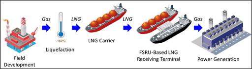
To bring natural gas produced from the major gas supply sources around the world to the major gas markets, which are usually located a long distance away, natural gas is either transported to market by a long distance pipeline or converted into LNG and then transported to market by a special purpose LNGC. The LNGC receives its LNG cargo at an LNG liquefaction plant in an exporting country and then delivers this LNG to an importing country, where the LNG is unloaded at an onshore or offshore LNG receiving terminal.
FSRU technology has developed and matured over the recent years since the start-up of the first project in 2007, and has been chosen by many governments / companies as a viable and cost effective design for an LNG receiving terminal where constraints exist concerning a large, onshore, land-based LNG receiving terminal.
An illustration of the full LNG Supply Chain with a FSRU-based LNG receiving terminal used for LNG importation is shown in Figure 2.1. At the gas producing country, the process of LNG production involves the transport of the natural gas from the production fields via pipeline to a liquefaction plant. Prior to liquefaction, the gas is treated to remove contaminants, such as carbon dioxide, water and sulphur to avoid them freezing and damaging equipment when the gas is cooled to -162°C where it enters its liquid state.
The LNG produced from the liquefaction process is piped into LNG storage tanks. The piping and equipment and the LNG storage tanks are thermally insulated to maintain the low cryogenic temperature. LNG storage tanks are designed and constructed using special materials to contain the cryogenic liquid LNG.
When required for send-out from the liquefaction plant, LNG is pumped from the LNG storage tanks, and loaded onto a specially equipped LNGC and then transported to the LNG importing country.
When the LNGC arrives at the place of import, LNG is unloaded from the LNGC onto the FSRU Vessel moored at the LNG receiving terminal where it is stored on board in the LNG storage tanks. Then, when required to meet local gas demand, the LNG is re-gasified into natural gas and sent out to end-users, such as power plants and major industries, by high pressure pipelines.
Figure 2.1 LNG Supply Chain including Offshore LNG Receiving Terminal
Offshore LNG Receiving Terminal Key Components and Process
An offshore LNG receiving terminal is located towards the end of the gas supply chain and operates in the same manner as a conventional onshore, land-based LNG receiving terminal.
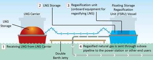
Typical key features of the FSRU based LNG Terminal for the Project are as follows:
Ÿ FSRU Vessel permanently moored at the Jetty (except under adverse weather conditions) which has the following on-board facilities;
- LNG storage tanks – either Membrane (the LNG storage tank matches the configuration of the hull of the FSRU Vessel) or MOSS (the LNG storage tank is spherical);
- LNG regasification units – e.g. LNG booster pumps, LNG vaporizers, etc.
Ÿ Jetty which has a double berth for mooring both the FSRU Vessel and the LNGCs that deliver the LNG; together with LNG unloading arms and transfer piping and high pressure gas send-out arms, metering equipment and piping ; and
Ÿ Subsea pipelines connecting the Jetty to the end-users i.e. the BPPS and the LPS.
The key components and process overview of an FSRU Vessel and the Jetty are depicted in Figure 2.2.
Figure 2.2 Offshore LNG Receiving Terminal Key Components and Process Overview
The FSRU Vessel design and operations will be under internationally accepted merchant shipping standards such as the International Maritime Organization (IMO) International Code for the Construction and Equipment of Ships Carrying Liquefied Gases in Bulk (IGC Code) and ship classification society regulations. The FSRU Vessel is required to comply with the same strict international regulations and industry guidelines as LNGCs that have been in place since the start of the LNG industry over 50 years ago, an industry that has since grown substantially worldwide and has an outstanding safety record.
International FSRU Based LNG Import Projects
Over recent years, offshore LNG import projects using FSRU technology have been chosen over onshore, land-based projects, and this trend is set to continue as FSRU based LNG import projects are proving to be a viable and cost-effective solution overcoming many of the permitting and environmental constraints that are typically faced by large, onshore, land-based infrastructure developments. As of April 2018, there are 22 FSRU based LNG import projects in operation; and many projects are in various stages of development around the world.
In the history of LNG shipping (1964-2017), LNGCs have demonstrated an outstanding industry safety record and have rarely been involved in collisions and groundings; none of these leading to a breach of an on-board LNG storage tank.
Since the first FSRU based LNG import project was commissioned in 2009, up to the present time (2017), there have been no accidents ([19]). This excellent operational safety record has been maintained through the application of rigorous safety policies, stringent design codes and operational practices implemented by the LNG industry.
With Hong Kong’s rising demand for land availability being a significant development constraint, coupled with the advantages of a remote offshore location in HKSAR waters, this leads to the conclusion that the Hong Kong Offshore LNG Terminal based on FSRU technology, together with its quicker construction time, lower capital cost and reduced environmental impact is, therefore, the preferred choice over an onshore, land-based LNG import terminal.
2.3 Consideration of the Site and Layout Options for the LNG Terminal
2.3.1 Introduction
In early 2015 CLP commenced work on the identification of potential locations within Hong Kong that could accommodate the LNG Terminal and its associated infrastructure required for the Project. The following section details the processes by which a suitable location (‘Study Area’) was identified, selected and recommended for more detailed analysis as part of this EIA Study in order to determine the actual Site for the LNG Terminal.
2.3.2 Selection of the Preferred LNG Terminal Location
The approach to selecting suitable locations for the LNG Terminal Site has been based on other site search studies conducted in Hong Kong ([20]) ([21]) ([22]) ([23]) ([24]). The approach was organised into two main phases, the first focussed mainly on excluding incompatible areas and the second in narrowing down to a most preferred /suitable location. In order to guide the site selection procedure, the key engineering requirements were referred to, in particular, marine access and berthing requirements and met-ocean conditions.
Absolute Constraints
These factors are seen to pose an ‘absolute’ obstacle to the development of the Project justified by the presence of highly significant issues. These are used for the preliminary elimination of all unsuitable locations to facilitate the establishment of ‘No Go Areas’, including statutory protected locations at which the LNG Terminal would not be allowed to be constructed and are, therefore, avoided from the outset. These Absolute Constraints, which were grouped into Marine Safety and Environmental categories, were applied as the first screen to eliminate unsuitable locations so as to identify potential locations for the LNG Terminal Site that were available within Hong Kong waters.
Marine Safety Constraints
The LNG Terminal when operating will involve the transfer and storage of LNG, as well as the regasification of the LNG and send out of natural gas at high pressure in subsea pipelines. Consequently, it is critical from a safety perspective that the LNG Terminal is away from areas of heavy marine traffic and nearby populations, and is not overly exposed to adverse weather or met-ocean conditions. Therefore, areas of Hong Kong waters that are designed for marine traffic purposes were excluded from further consideration and these included:
· Marine Vessel Fairways;
· Access Channels and Traffic Separation Schemes;
· Restricted Areas (high/low/unrestricted traffic volume);
· Existing Anchorages (dangerous goods, immigration and others); and
· Gazetted Typhoon Shelters and Marina.
The siting of the LNG Terminal also gave consideration to operational limits for navigation, berthing, loading/unloading, gas export, and mooring. For safe transit and approach, a water depth of approximately -15 metres Chart Datum (mCD) is required. Certain depth limitations can be overcome by engineering solutions, for instance, the lack of water depth can be compensated for by dredging. However, a balance should be struck between the extent of engineering solutions which have the potential to introduce additional environmental impacts and minimum met-ocean thresholds required. Therefore a water depth of shallower than -10mCD was applied as an absolute constraint.
Stability of the moored FSRU vessel and the LNGC is important during LNG unloading and transfer and gas send out to avoid accidental spills of the cryogenic liquid. Consequently, areas in Hong Kong waters that experience extreme wave heights or high current speeds were excluded from further consideration.
The limiting extreme wave height for navigation is assumed to be at 3.5m. Given the interactive nature of wind, wave and current (see operational limits for FSRU vessel and LNGC operations in Table 2.2), wind speed alone is not necessary a limiting factor to FSRU vessel and LNGC operations, but its compound effect on wave height could affect their operations. Peak current speed tolerances for berthing during wet and dry seasons in ebb and flow were modelled and applied. The limiting current speed for berthing, LNG unloading and regasification and send-out operations was assumed to be 0.6ms-1.
Environmental & Conservation Constraints
Areas that have been designated for environmental conservation were also excluded from further consideration and these included:
· Designated Marine Parks and Marine Reserves;
· Sites of Special Scientific Interest (SSSI);
· Coastal Protection Areas;
· Country Parks and Special Areas;
· Mai Po Nature Reserve Area;
· Restricted Areas gazetted under Wild Animals Protection Ordinance;
· Fish Culture Zones;
· Gazetted Artificial Reefs; and
· Gazetted Beaches.
All of the above constraints have some form of development control which would either render the development of the LNG Terminal in these areas unsuitable or involve significant permitting challenges that would add prohibitive costs and time to gain all necessary approvals required to develop the LNG Terminal.
The above Absolute Constraint layers were collated to create a map of “No Go Areas”, as shown in Figure 2.3.
It is apparent from this process that the majority of marine areas in western and north-western waters were excluded as part of the constraint mapping exercise. This includes the area around the BPPS, an end-user of natural gas from the LNG Terminal. The rationale for this is that the majority of these areas have relatively high current speeds and are very shallow and, therefore, would require substantial dredging to be able to accommodate the LNG Terminal. The areas of deeper water that have the required depth of -15mCD are typically shipping lanes or fairways and hence are not suitable for siting the LNG Terminal. In addition the transit routes for the LNGCs in these areas are not considered suitable due to the presence of heavy marine traffic.
The constraint mapping exercise also excluded the majority of marine areas in central waters north of Lamma Island. This is because these areas have a number of maritime and port operations that represent safety constraints to the LNG Terminal as well as LNGC transit. The majority of these areas also have relatively high current speeds and are shallow and, therefore, would require substantial dredging to be able to accommodate the LNG Terminal. The areas to the southwest of Lamma Island also experience extreme wave heights (> 3.5m) and hence are not suitable for siting the LNG Terminal.
Following the identification of less constrained areas (i.e. those areas outside the Absolute Constraint areas), a further review was conducted considering the availability of space to accommodate the proposed LNG Terminal, which for the site selection exercise was assumed to be about 29ha ([25]). Areas that were considered inadequate to accommodate the LNG Terminal were, therefore, eliminated (see Figure 2.4). Therefore, a total of nine (9) potential locations were identified as shown in Figure 2.4.
Potential Constraints
Further to the Absolute Constraints, potential locations were mapped against ‘Potential Constraint’ factors. These factors may render potential locations undesirable due to an established or proposed use, environmental value and / or technical challenges amongst other reasons. Although considered not to prevent locating the LNG Terminal, these constraints pose significant issues or implications that may potentially present an obstacle to the development of the Project, and risk its safe and timely delivery. The potential constraints covered four main categories:
1. Marine: (a) ease of navigation of LNGCs transit route; (b) dredging requirements for LNG Terminal and LNGCs transit route; (c) presence of subsea utilities; and, (d) presence of designated mud disposal/sand dredging areas.
2. Environmental: (a) proposed and potential areas of conservation interest, including marine parks and geoparks; (b) marine mammal habitats; (c) fisheries resources, spawning and nursery areas; and (d) coastal ecological resources such as corals, mangroves etc.
3. Planning: (a) proposed and potential land developments; (b) proximity to the BPPS; and, (c) proximity to the LPS.
4. Social: (a) marine recreation areas including secondary contact zone; and, (b) size and distance of nearest population.
The areas excluded by the Absolute Constraints were mapped out and the remaining areas examined with reference to the Potential Constraints, see Figure 2.5. This process helped identify locations that could be considered as suitable for siting the LNG Terminal.
The nine potential locations were considered for their practicality for siting an LNG Terminal, access by LNGCs, and their surrounding environment. Potential locations that face multiple constraints and/or are likely to pose challenges to the practicality of the FSRU facility were eliminated.
A number of factors that were considered to make some potential locations in the eastern and southern part of Hong Kong not practical included: near high marine traffic on marine fairways (posing constraints to LNGC transit) and recreational marine usage; within secondary contact recreational zones; limited space for LNGCs transit and manoeuvring; adjacent to anchorage sites; long distance to major users (GRSs at the BPPS and the LPS); within or in close proximity to Geoparks, SSSIs or adjacent to numerous areas of conservation interest or high ecological value; and proximity to large populations.
As a result of these constraints, of the nine potential locations, considering the less constrained areas that were considered to be of sufficient size for the LNG Terminal Site and broadly accessible by an LNGC, six potential locations were not taken forward and three shortlisted potential locations (West Lamma, South of Cheung Chau & Shek Kwu Chau, and Southwest Hong Kong Water Boundary) were identified and examined further.
Review of the Three Shortlisted Potential Locations
West Lamma
This potential location is west of Lamma Island, adjacent to the Lamma Power Station Access Channel. The total size of the potential location is approximately 150ha. It covers marine waters in the West Lamma Channel, and is south of the confluence of Adamasta Channel, East Lamma Channel in central Hong Kong waters. The nearest population can be found near the ferry pier at Yung Shue Wan about 2km away.
• Marine: this potential location experiences marine traffic along the West Lamma Channel. LNGCs will likely approach the potential location via the southern Hong Kong waters, passing the three anchorages sites south of Lamma, and up north along the Lamma Power Station Access Channel. Depending on the frequency of use of the Access Channel, the LNGCs transit may be able to share this existing channel. However, the potential area for siting the LNG Terminal is not considered to be large and therefore may constrain LNGCs movements and any collision would potentially affect both coal and gas power supplies. This potential location also covers an existing subsea pipeline from Dapeng supplying gas to Lamma Power Station. The water depth is about -10mCD therefore moderate dredging is required for the LNG Terminal.
• Environmental: the potential location is generally away from areas of conservation interest or important ecological habitats. Hard coral communities have been recorded along the western Lamma coasts in patchy distribution, but generally of low coverage ([26]). However, the potential location is considered to be within the habitat of Finless Porpoises in southern Hong Kong waters, as southwestern part of Lamma Island has been identified as a calving area for Finless Porpoises typically most abundant during winter and spring seasons ([27]) ([28]).
• Planning: the potential location is closest to the GRS at the LPS, and is relatively further to the BPPS compared to the other shortlisted potential locations. At present, this potential location is not within areas of known proposed or potential development; however it falls within the study area of the proposed artificial islands in the central waters.
• Social: the potential location is located near secondary contact recreation zones around Lamma Island, as well as gazetted bathing beaches on the west coast of Lamma Island. The nearest population can be found in Yung Shue Wan within 2km of approximately 1,200 people (and Lamma Island has a total population of about 6,000) which is considered to be medium sized.
In summary, the major advantages of locating the LNG Terminal at the potential location at West Lamma are that it is away from proposed and potential development, area of conservation interest and important coastal ecological resources. However, this potential location is in a busy marine traffic area within the West Lamma Channel, its area is restricted by Lamma Power Station Access Channel to the right, which are potential concerns for LNGCs transit routing and the siting of the LNG Terminal, and moderate dredging would be required.
South of Cheung Chau & Shek Kwu Chau
This potential location refers to the southern waters surrounding Cheung Chau and Shek Kwu Chau in the south of Lantau Island. The total size of the potential location is approximately 950ha and is constrained by a typhoon shelter at the west of Cheung Chau. The nearest population can be found on Cheung Chau and relatively few populations on Shek Kwu Chau. The potential location is situated within two major marine vessel fairways with constricted directions and, therefore, LNGC transit would have to approach the potential location following set marine traffic schemes.
• Marine: the potential location experiences significant amounts of marine traffic as the Adamasta Channel to the north and the channel to the south of the location are main fairways for vessels arriving and departing Hong Kong, including regular high speed ferry services to Macau, river trade vessels and several outlying island ferry services ([29]). The Adamasta Channel is a constricted passage between Cheung Chau Island and Chi Ma Wan Peninsula on Lantau Island, with a water depth that ranges from -10 to -15mCD. Any construction obstructing this channel would pose significant complications and delays to marine traffic ([30]). Furthermore, Cheung Chau piers experience traffic from small crafts and fishing boats. All these factors render access to the potential location challenging for LNGCs transit. One option for LNGCs approach would be by making a left turn from the West Lamma Channel, and entering and exiting the marine vessel fairway south of the potential location following its set direction. The water depth at this potential location is about -10mCD therefore moderate dredging is required for the LNG Terminal. Several subsea cables and pipelines run from Cheung Chau and Shek Kwu Chau to the south of Lantau Island.
• Environmental: South of Cheung Chau and Shek Kwu Chau waters is known habitat for Finless Porpoise. Chinese White Dolphins have been recorded in south Lantau waters ([31]). The entire potential location falls within the study area of the proposed artificial islands in the central waters. Shek Kwu Chau is a designated conservation area. Their coastlines, together with the eastern coast of Cheung Chau, are coastal protection areas. Nevertheless, the potential location does not cover known habitats of other important ecological resources.
• Planning: the potential location is located relatively closer to the GRS at the LPS and the GRS at the BPPS. The west of Shek Kwu Chau has been earmarked for the location of the IWMF project.
• Social: Cheung Chau has a population of about 23,000 people and is bounded by the potential location. The population is considered to be large. Both Cheung Chau and Shek Kwu Chau are encircled by secondary contact recreation zones.
In summary, the major advantages of locating the LNG Terminal at the potential location at South of Cheung Chau & Shek Kwu Chau are its relatively closer distance to the GRS at the LPS and the BPPS, and away from important coastal ecological resources. However, the potential location is inconveniently located within two busy marine vessel fairways with set directions, which means that LNGCs would likely need to approach the potential location by making a sharp left turn into West Lamma Channel, which pose significant challenges to LNGCs transit.
Southwest Hong Kong Water Boundary
This potential location refers to the area in the south of Lantau Island in the southwest of Hong Kong water boundary. The total size of the potential location is approximately 3,100ha. It covers marine waters east of Tau Lo Chau, Soko Islands, south of Shek Kwu Chau and Cheung Chau. The nearest population is at Sha Tsui on Lantau Island of about 1,200 people and 5.4km from the nearest boundary of the potential location. The north of the potential location is the high speed craft channel used for many ferry services to Macau and outlying islands.
• Marine: the potential location experiences some traffic from the high speed craft channel south of Adamasta Channel which can be utilized for LNGCs transit. Since the potential location is located close to the southern HKSAR waters boundary, it is considered relatively accessible by LNGCs. LNGCs transit can approach the potential location by travelling outside the HKSAR waters boundary through the Danggan Channel from the east or Zhujiang Traffic Separation Schemes from the west. It is noted that many (11) subsea cables run through the potential location from Lantau Island to Hong Kong; however the potential location is considered to be able to locate the LNG Terminal between cables, or outside the subsea cable corridor, subject to detailed evaluation to confirm that the LNG Terminal Jetty can be safely constructed in a suitable location in the vicinity of the subsea cables (see Section 2.3.3). The water depth at the potential location is about -10 to -15mCD therefore moderate to minimum \ no dredging may be required for the LNG Terminal.
• Environmental: Similar to the potential location at South of Cheung Chau & Shek Kwu Chau, this potential location is a known habitat for Finless Porpoises and Chinese White Dolphins have been recorded in south Lantau waters. It is partially covered the proposed South Lantau Marine Park.
• Planning: this potential location is comparatively relatively close to the GRS at the LPS, and is the closest to the GRS at the BPPS. The potential location is also located away from proposed and potential development, and the majority of the potential location falls within the study area of the proposed artificial islands in the central waters.
• Social: this potential location is the most distant away from population with the smallest nearby population of 1,200 people in Sha Tsui on Lantau Island. Due to its remote location, it is also not within secondary contact recreation zones or areas with high recreational marine traffic, and is therefore considered compatible with existing recreational uses.
In summary, the major advantages of locating the LNG Terminal at the potential location at South-West Hong Kong Water Boundary are its location away from densely populated areas, heavy marine traffic areas, and recreational use while being relatively closer to the GRS at the LPS and the BPPS. However, the potential location is within known habitats of the Finless Porpoises and close to the habitats of the Chinese White Dolphins, as well as partially covered by the proposed South Lantau Marine Park.
Summary of Key Advantages and Disadvantages of the Three Shortlisted Potential Locations
The key advantages and disadvantages of the three shortlisted potential locations are presented in Table 2.1.
Table 2.1 Summary of Key Advantages and Disadvantages of Three Shortlisted Potential Locations
|
Location |
Pros |
Cons |
|
West Lamma (southern Hong Kong)
|
Ÿ Away from areas of conservation interest and important coastal ecological resources Ÿ Deep waters with less dredging requirement
|
Ÿ Proximity to moderately populated areas Ÿ Within the Finless Porpoise habitats, including calving area Ÿ Close to Lamma Power Station Access Channel and West Lamma Channel, which are busy marine traffic areas Ÿ Covered by Dapeng LNG pipeline supplying Lamma Power Station but with sufficient space between pipeline routes for LNG Terminal Ÿ Relatively small potential area Ÿ Covered by the study area of the proposed artificial islands in the central waters Ÿ Water depth is about -10mCD with moderate dredging requirements Ÿ Near recreational zones and gazetted beaches |
|
South of Cheung Chau & Shek Kwu Chau |
Ÿ Away from areas of known habitats of other important ecological resources Ÿ Relatively sheltered met-ocean conditions |
Ÿ Proximity to densely populated areas Ÿ Between two high traffic marine vessel fairways posing constraints to LNGCs transit Ÿ Close to area of recreational uses Ÿ Within the Finless Porpoise habitats, and in proximity to the Chines White Dolphins habitats Ÿ In vicinity of IWMF Project Ÿ Water depth is about -10mCD with moderate dredging requirements Ÿ Partially covered by subsea cable utilities and pipelines
|
|
Southwest Hong Kong Water Boundary |
Ÿ Away from densely populated areas Ÿ Away from recreational zones Ÿ Relatively close to the pipeline connections to GRS at the LPS, and is the closest to the GRS at the BPPS. Ÿ Water depth is between -10 to -15mCD with moderate to minimum \no dredging requirements Ÿ Away from dense marine traffic areas Ÿ LNGCs transit is relatively simple as located close to southern HKSAR water boundary Ÿ LNGC transit is relatively short in HKSAR waters Ÿ Relatively large potential area |
Ÿ Within Finless Porpoise habitats, and in proximity to the Chines White Dolphins habitats Ÿ Partially covered by subsea cable utilities, but is considered to be able to safely locate LNG Terminal Jetty between cables, or outside the subsea cable corridor Ÿ Partially covered by the proposed SLMP and South Cheung Chau mud disposal site (Sediment Disposal Area) Ÿ Covered by the study area of the proposed artificial islands in the central waters
|
Identification of the Preferred Location (“Study Area”)
Of the three shortlisted potential locations, “Southwest Hong Kong Water Boundary” located east of the Soko Islands was selected for further analysis as the preferred location for the LNG Terminal Site for the following reasons:
· The preferred location is remote from populated areas and secondary recreational zones, with the closest populations located in southern Lantau Island and Cheung Chau at a distance of more than 5km;
· The preferred location is also located well away from designated marine vessel fairways and high-speed passenger ferry routes between Hong Kong and the Pearl River Delta;
· The preferred location has sufficient water depth of -10 to -15mCD with no or minimum dredging requirements for the LNG Terminal or the LNGC transit route, compared to other potential locations; and,
· The preferred location has relatively shorter LNGC transit route and is in relatively calm waters, sheltered from typhoon conditions, thereby considered as favourable to LNG Terminal operations.
The relative shortcomings of the preferred location for the LNG Terminal include its location within known habitats of species of conservation interest i.e. Finless Porpoise and Chinese White Dolphin, to the west, and the South Cheung Chau mud disposal site to the east. It is also in the vicinity of the proposed South Lantau Marine Park and submarine telecommunication cable corridor.
Further analysis has been carried out and is detailed in the following Sections in order to confirm the optimal Site for the LNG Terminal within the Southwest Hong Kong Water Boundary Study Area. The analysis considered the comments and feedback that were received from the relevant government departments and other environmental, marine, engineering, construction and operational considerations, as well as engaging with relevant stakeholders e.g. subsea cable owners, etc.
Section 2.3.3 below presents the outcomes from the detailed analysis of the Study Area, which includes environmental, marine, engineering, construction and operational considerations in order to ensure that the most suitable Site was selected for the LNG Terminal considering the future safe and reliable operation of the Project.
2.3.3 Selection of the Preferred LNG Terminal Site
Consideration of Environmental, Social and Marine Aspects Near to / within the Southwest Hong Kong Water Boundary (herein ‘the Study Area’)
The Study Area has been identified as the preferred location for the LNG Terminal. It is noted, however that, there remain some other uses related to the Study Area that need to be taken into consideration when selecting the most preferred location for the LNG Terminal.
South of Cheung Chau Open Sea Sediment Disposal Area (Sediment Disposal Area)
Close to the east side of the Study Area is the uncontaminated Sediment Disposal Area designated by the Civil Engineering and Development Department (CEDD). This Sediment Disposal Area is the only one in Hong Kong that can receive sediments all year round and consequently, it is of strategic importance to the Fill Management Division of CEDD. Southwest of the Study Area there is relatively deep water and is considered dispersive as seabed currents and waves gradually disperse the marine sediments into the surrounding marine areas.
Given the use of the Sediment Disposal Area to the east of the Study Area, this is considered to be relatively less environmentally sensitive.
CEDD has indicated that due to the importance of their Sediment Disposal Area for receiving dredged sediment on a year round basis; this should not be compromised by the future operations at the LNG Terminal. CLP and HK Electric recognise the need to maintain the all year operation of the Sediment Disposal Area and supports close coordination and management with CEDD to ensure that both operations can co-exist in an otherwise unoccupied offshore area of the HKSAR waters.
Consequently, locating the LNG Terminal adjacent to the Sediment Disposal Area would be beneficial as it is a relatively less environmentally sensitive. Although there are potential future operational interface to be considered, these can be overcome by design solutions and close planning and establishing an operational interface with the CEDD who is responsible for the management of the Sediment Disposal Area operations.
Marine Traffic Fairways
Locating the LNG Terminal in the Study Area will avoid all existing navigation channels, vessel fairways and other shipping lanes which will help reduce potential collision from passing marine traffic.
It is also considered prudent, from a safe operations perspective, for the LNG Terminal to be located at a Site that is a suitable distance from areas of busy marine traffic. To the north of the Study Area is the Adamasta Channel traffic separation scheme which is a recommended route for high speed craft. To the south of the Study Area is the Zhujiang / Pearl River Estuary TSS which is used by ocean going vessels transiting to and from the ports in the Pearl River Delta. It is desirable to maintain a large a distance as possible between the LNG Terminal Jetty and the busy shipping lane frequently used by large vessels just outside of the HKSAR maritime boundary to decrease the collision risk potential, and also to maintain the maneuvering water space available and to avoid restricting the ability of the FSRU Vessel to berth at the LNG Terminal Jetty from the southern approach, if needed.
The Jetty Marine Traffic Impact Assessment (MTIA) that was carried out for the Study Area has demonstrated a low level of marine traffic activities, and these are mainly from fishing vessels and small crafts, which gives a lower risk of collision damage around the Site of the LNG Terminal.
Consequently, the Study Area is an area of low marine traffic, and a suitable separation distance from the boundary of the various marine vessel fairways and the Site of the LNG Terminal can be achieved.
Subsea Telecommunications Cables
To the west of the Study Area, there are ten (10) existing subsea telecommunications cables that run in a north / south direction under the seabed in what is termed the SW Lantau cable corridor. It is preferred that the location of the LNG Terminal is in an area free of existing subsea cables in order to reduce the risk of disruption and reduce Jetty construction risk, although the BPPS Pipeline will have to cross these subsea cables.
Consequently a Site for the LNG Terminal within the Study Area that avoids disturbance to these important subsea telecommunications cables is preferred.
As stated above, it is noted that the BPPS Pipeline connecting the LNG Terminal to the GRS at the BPPS will need to cross these cables (and in two (2) other locations along the LPS Pipeline route to the GRS at the LPS it also is required to cross subsea cables), therefore the input from and an agreement with the Subsea Cable Owners on the design and construction of the subsea pipeline / cable crossings will be required.
Consequently, interference between the location of the LNG Terminal and the existing subsea telecommunications cables is required to be minimised, and suitable engineering and construction special crossing arrangements are required where the subsea BPPS Pipeline and LPS Pipeline will cross any subsea cables. Appropriate design will be carefully studied and reviewed by the Project Proponent. Design will consider provisions to allow future new or replacement subsea cables to cross the BPPS Pipeline and the LPS Pipeline without impacting the integrity of the new cables, and the safety concern of installation across the Pipelines.
Proposed South Lantau Marine Park (SLMP)
A marine park area of at least 700ha is to be established as a mitigation measure for the Integrated Waste Management Facility (IWMF) under the project’s Environmental Permit (EP-429/2012). This proposed marine park will be located between Shek Kwu Chau and the Soko Islands as indicated in the approved EIA Report; the exact boundary of this marine park is yet to be finalised by EPD, whilst this proposed marine park will be administered by the AFCD. The timing of its designation is to be confirmed, with the project’s Environmental Permit (EP-429/2012/A) requiring designation immediately following the completion of construction works of the IWMF ([32]).
The detailed design and progress on the development of the proposed compensatory marine park of the IWMF Project and the proposed Soko Islands Marine Park were briefed to the Country and Marine Parks Board on 24 Nov 2017 ([33]). To achieve better synergy in the future management of these two Marine Parks, it is proposed by AFCD to combine them into one single marine park of approximately 2,067ha, to be named as the South Lantau Marine Park (SLMP). This approach will facilitate the future management and operation of the SLMP in terms of maintenance of facilities, enforcement and patrolling, implementation of fisheries enhancement measures, etc.
The location for the LNG Terminal has avoided the proposed SLMP and buffer distance to the proposed SLMP (approximately 100m) has been maintained considering other environmental and operational constraints in the vicinity. The buffer distance is demonstrated to be adequate based on no indirect water quality and marine ecological impacts on the proposed SLMP during the construction and operation phases of this Project.
There are no unacceptable impacts on the proposed SLMP from monitoring and management of third parties during operations of the LNG Terminal.
Consequently, the location of the Site of the LNG Terminal has taken into consideration the establishment of the boundary of the SLMP and a buffer distance has been maintained where practicable considering other environmental and operational constraints in the vicinity, and with no unacceptable impacts on the proposed SLMP from monitoring and management of third parties during operations of the LNG Terminal.
Distance to Land / Residential Areas
The nearest land masses to the Study Area are the unoccupied Soko Islands at approximately 2.5km (including Tau Lo Chau, at approximately 1.6km) to the west, whose potential users may include recreational users, and future users (e.g. of a potential spa and resort); and Shek Kwu Chau at approximately 4.5km to the north, whose potential users may include staff and inmates at a drug rehabilitation center and also future users around Shek Kwu Chau (e.g. proposed Integrated Waste Management Facilities).
The closest residential area to the Study Area are further north on Cheung Chau at approximately 7km away, however the views to the Study Area from the ferry pier and harbour town area are largely obscured by the seawalls protecting the Cheung Chau Typhoon shelter, as well as vessels in the bay.
The nearest recreational zones and residential areas on Lantau include the southern coastline of Lantau (approximately 7km away) and hiking trails on Lantau (at least 6km away).
Consequently, to minimise the potential impacts on recreational zones and potential existing and future users of the nearest land masses, the distance to the Site of the LNG Terminal has been maximized, i.e. located to the southeast of the Study Area.
Marine Mammal Population Density
Long-term monitoring studies carried out by AFCD and baseline surveys conducted for this EIA Study have mapped the population densities of both Chinese White Dolphin (CWD) and Finless Porpoise (FP) throughout the Study Area. The results indicate that relatively few CWD frequent the Study Area. In terms of FP population densities, the results indicate that FP densities are relatively lower to the east of the Study Area.
Consequently, to minimise the potential impacts on CWD and FP the Site of the LNG Terminal has been located to the east of the Study Area.
Operational Considerations
A number of marine and engineering studies have been undertaken focused on the Study Area, in parallel with the mapping of environmental, social, marine and planning constraints to develop the Site and layout arrangements of the LNG Terminal. Met-ocean studies were carried out considering the water depth, wave movement, wave heights, current speeds, winds impact etc. to refine the proposed Site for the LNG Terminal within the Study Area. In addition, a Mooring System Design Study was carried out to ensure that the FSRU Vessel (and an LNGC) can safely berth, and could remain on berth throughout the prevailing met-ocean conditions; the exception being the onset of a typhoon when the FSRU Vessel and an LNGC (if on berth at the time) would be required to deberth from the Jetty and sail to a safe location to avoid the typhoon.
As part of the studies referenced above, navigation simulations were carried out to confirm that the FSRU Vessel and an LNGC could transit to the Jetty, safely berth, and depart under normal operating and emergency conditions, and this does not impact the marine traffic passing to the south, or any adjacent marine facilities.
Ÿ FSRU Vessel and LNGC Operational Limits: Typical FSRU Vessel / LNGC operational limits for the Project based on other FSRU based LNG import projects and available met-ocean data on wind, waves and currents for the navigation approach, berthing and mooring of the FSRU Vessel and LNGCs alongside the Jetty, followed by the safe, simultaneous LNG unloading operations and send-out of natural gas have been assessed. These operational limits are based on LNG industry practice and information available during the preparation of this EIA Study and have been used to refine the selection of the preferred Site for the LNG Terminal and are presented in Table 2.2.
Table 2.2 Typical Operational Limits for FSRU Vessel and LNGC Operations
|
|
Limiting Wind Speed (m s-1)* |
Limiting Wave Height (m) |
Limiting Current Speed (m s-1) |
|
Navigation |
26.0 |
3.5 |
1.54
|
|
Berthing |
12.0 |
2.0 |
0.6
|
|
LNG Unloading Operations |
19.0 |
2.0 |
0.6
|
|
Jetty Mooring |
26.0 |
2.25 |
0.8
|
* Note that the table shows assumed sets of limits for wind, waves and currents which in reality are interactive, i.e. lowering the wind speed could potentially increase the tolerance of wave height and current speed. Specific met-ocean limits will be further determined during the implementation of the Project.
Ÿ FSRU Vessel / LNGC Transit in Hong Kong Waters: In general, the shorter the distance travelled, and less complex the manoeuvres required to be carried out in HKSAR waters by the FSRU Vessel and a visiting LNGC is preferred. As such, siting the LNG Terminal to the south of the Study Area is preferable.
Ÿ Met-ocean Conditions: An assessment of the met-ocean criteria (covering water depth, winds, waves, currents) coupled with a review of physical constraints (proximity to the BPPS and the LPS, Marine Parks, marine navigation and Sediment Disposal Area exclusions) has confirmed that the Study Area is the preferred location for the Site of the LNG Terminal. Siting an LNG Terminal outside the Study Area places it in areas where there are strong currents or shallow water (requiring significant dredging), or in the vicinity of busy shipping lanes, or a combination of the above.
n Bathymetry: The Met-ocean Study has shown that the eastern half of the Study Area has a water depth exceeding 15m which is suitable for safe LNG Terminal operations including FSRU Vessel and LNGC arrivals and departures. It has also been shown that the western half of the Study Area has water depths between 10 to 15m, therefore for this area to be suitable for safe LNG Terminal operations including FSRU Vessel and the more frequent LNGC arrivals and departures, capital and maintenance dredging to create a berthing pocket and potentially a navigation access channel, is likely to be required.
n Winds: It is considered that the wind speed / directionality is not significantly different across the Study Area therefore this is not considered a key determining factor in locating the LNG Terminal within the Study Area.
n Waves: The frequency of wave activities across the Study Area illustrates an essentially uniform distribution. The Study Area is considered suitable for LNG Terminal operations almost all year round, including FSRU Vessel and the more frequent LNGC arrivals and departures; therefore this is not considered a key determining factor in locating the LNG Terminal within the Study Area.
n Currents: Flood and Ebb tides, and related local currents, have a relatively uniform intensity across the Study Area, at a similar orientation to the peak wave energy. Current levels within the Study Area fall well below those required to inhibit safe LNG Terminal operations, including FSRU Vessel and the more frequent LNGC arrivals and departures, therefore this is not considered a key determining factor in locating the LNG Terminal within the Study Area.
Taken together, from the point of view of considering all of the above factors including marine traffic densities, FSRU Vessel and LNGC transits, and met-ocean conditions (including bathymetry, wind, waves, currents), the Study Area is found to be a suitable location for safe LNG Terminal operations – provided that the alignment of the LNG Terminal Jetty is arranged such that the dominant directions of waves and currents are respected, and that the most suitable side of the Jetty is selected for the permanent mooring of the FSRU Vessel.
Therefore, the Study Area was further assessed in order to determine the optimum location and orientation of the LNG Terminal.
2.3.4 Preferred Site and Orientation of LNG Terminal
Siting
The environmental and physical constraints in the vicinity of the LNG Terminal are illustrated in Figure 2.6. It was identified that the eastern corner of the Study Area is best suited for siting the LNG Terminal. However, it is noted that three existing subsea cables (which are buried within the seabed) cross this area, therefore it is not be possible to locate the LNG Terminal directly within the subsea cable area. As such, other potential location options were considered for the Site of the LNG Terminal as shown in Figure 2.7, and their relative merits / demerits are discussed below.
1. Position A: Located in an available water space in close proximity to two existing subsea cables; where FSRU Vessel and LNGC access could be achieved with the minimum of dredging (if any); or
2. Position B: Located in an available water space west of the Study Area; with a greater separation distance between two existing subsea cables than Position A. However, the water depth is less at this location, and this would require dredging to provide a berthing pocket and a navigation channel to the LNG Terminal.
3. Position C: Located in an available water space at the eastern boundary of the Study Area, with a constraint being its proximity to the Sediment Disposal Area. However, the deeper water depth means that the FSRU Vessel and LNGC access could be achieved with the minimum of dredging (if any), and a shorter distance to travel to the LNG Terminal.
Figure 2.7 Potential Sites for the LNG Terminal
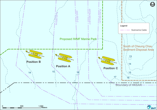
As discussed above, Position A and Position B were considered as other potential options for the Site of the LNG Terminal, however, it was identified that the water depths at these locations are shallower than at Position C, and access north of the LNG Terminal with a fully laden LNGC may not be viable at some states of the tide.
Therefore, Position C was identified as the preferred Site for the LNG Terminal as it is in deeper water and is a little closer to the HKSAR’s boundary (i.e. relatively less distance to travel by the LNGC); the constraint being the orientation required to achieve an adequate clearance from the existing subsea cables, and the proximity to the Sediment Disposal Area.
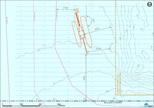
Orientation
The boundary conditions related to the Site for the LNG Terminal at Position C are (i) the nominal offset of 500m from the HKSAR southern waters boundary and the boundary of the Sediment Disposal Area stipulated by the Civil Engineering and Development Department and (ii) a predefined 200m separation from the nearest subsea cable to the west.
The preferred orientation of the Jetty, was selected on the basis of:
Ÿ Accessibility: The ease of access arrangements to the LNG Terminal under normal weather conditions for arrival and extreme weather conditions for departure; also considering if potential dredging may be required; and
Ÿ Operability: Loss of availability - as the orientation turns and the Jetty is positioned perpendicular to the dominant incident waves, increasing motions of the vessels and tolerances of lines and couplings.
In view of setting a balance between accessibility and operability, and recognizing the proximity to the Sediment Disposal Area and the proposed SLMP to Position C, the preferred orientation of the LNG Terminal is at 165° North, as illustrated below in Figure 2.8.
Figure 2.8 Preferred Orientation of the LNG Terminal
Conclusion
In the selection of the preferred Site for the LNG Terminal, full consideration has been given to the environmental, social, and marine constraints, and related benefits including suitable water depth to minimize the need for dredging; avoiding the nearby proposed SLMP; and the Site being in an area of relatively lower FP density (as identified by AFCD’s long-term monitoring and baseline surveys conducted for the EIA Study).
A benefit from the selection of Position C is that it maximizes the relative distance of the Site from the Soko Islands (including Tau Lo Chau), Shek Kwu Chau and the closest residential areas approximately 7km away on Cheung Chau and southern Lantau. The proposed Site for the LNG Terminal is to the west of the Sediment Disposal Area, which is considered to be a relatively less environmentally sensitive location.
Further, the proposed Site of the LNG Terminal and its navigation approach and manoeuvring / turning area) has also been determined on the basis of a number of operational considerations, i.e. the required water depth of >15m, the relatively low wave heights (minimizing exposure to swells and consequent disruption to LNG unloading operations), relatively lower peak current speeds of 1-1.5 knots (minimizing navigational impacts) and low marine traffic densities (minimizing impacts to/from other passing marine vessels), in addition to direct, close access to/from open HKSAR waters (benefitting navigation and access by the FSRU Vessel and the LNGCs to the LNG Terminal).
The environmental benefits and dis-benefits for the proposed Site of the LNG Terminal are presented below:
Benefits
1. Adjacent to the relatively less environmentally sensitive Sediment Disposal Area, but a manageable distance away;
2. Maintains a suitable separation distance from the boundary of the various vessel fairways;
3. Minimizes the proximity to and interference with the existing subsea cables;
4. Outside the boundary limits for the proposed SLMP;
5. Maximises the distance from potential existing and future users of the nearest land masses including the closest population on Cheung Chau and South Lantau, as well as potential existing or future users of Soko Islands (including Tau Lo Chau) and Shek Kwu Chau;
6. Maximises the distance from recreational zones;
7. In an area with few CWD, and relatively less FP;
8. Maximum water depth and thus minimizes requirements for capital and maintenance dredging and related marine sediment disposal;
9. Not in proximity to dense marine traffic areas; and
10. The transit of the FSRU Vessel and the LNGCs through HKSAR waters to the Site is relatively short.
Dis-benefits
1. Close planning and future operations interface with relevant Government departments, such as CEDD related to the proximity of the Site to the Sediment Disposal Area;
2. Close planning and future operations interface with relevant Government departments, such as AFCD related to the proximity to the proposed SLMP.
3. The LNG Terminal Jetty is in the vicinity of a subsea cable to the eastern boundary of the South West Lantau cable corridor.
Consequently, considering all of the above factors including access arrangements and operability, and with no unacceptable impacts on the proposed SLMP from monitoring and management of third parties during operations of the LNG Terminal, Position C with an orientation of 165° North is found to be the preferred Site for the LNG Terminal.
2.4 Consideration of Alignment options for BPPS Pipeline
2.4.1 Marine Only vs Marine-Land-Marine Approach
Based on the preferred Site for the LNG Terminal, a number of alternative alignment (herein also referred to as ‘route’) options were considered by CLP for the BPPS Pipeline that runs from the LNG Terminal to the GRS at the BPPS.
Three ‘marine only’ route options were considered for the pipeline route to BPPS, namely (i) Option B1: a subsea route running west from the LNG Terminal to the south of the SLMP, then passing to the southwest of Lantau Island, then running north to the landfall at the BPPS; (ii) Option B2: a subsea route running north from the LNG Terminal, then to the north of the proposed SLMP; and (iii) Option B3: a subsea route running west from the LNG Terminal through the proposed SLMP towards the Soko Islands, then turning south and running to the south of the Soko Islands (see Figures 2.9a-c).
A ‘marine – land – marine’ route option was also considered namely Option B4: a route running subsea west from the LNG Terminal, then turning to the north to a landfall on Lantau Island, then traversing Lantau Island (either buried below ground, or in a tunnel), then departing Lantau Island to join the subsea route running north to the landfall at the BPPS (see Figures 2.9a-c).
The BPPS Pipeline route options have been broadly defined, to enable their review and further refinement. As part of the pipeline route selection exercise, environmental, physical, risk and constructability constraints were reviewed to determine the most appropriate pipeline route where environmental impacts can be managed and mitigated.
Environmental Issues
Areas of known environmental importance in the marine and terrestrial environment (i.e. in western HKSAR waters, and on Lantau Island) through which the BPPS Pipeline may pass have been identified. The environmentally important areas and issues for the BPPS Pipeline route are illustrated in Figure 2.9a and discussed in Table 2.3.
Table 2.3 Environmental Issues for BPPS Pipeline Options
|
Issues |
Notes |
Marine Based (1) |
|
|
· Designated Marine Parks |
There is one designated Marine Park at Sha Chau and Lung Kwu Chau. Marine Parks are gazetted for conservation, recreation and educational purposes and are under the control of the Country and Marine Parks Authority (CMPA).
|
|
· Proposed Marine Parks |
There are several proposed Marine Park at South Lantau, Southwest Lantau, and the Marine Park related to the Airport’s Third Runway System in western Hong Kong waters.
|
|
· Fish Culture Zones |
There is a Fish Culture Zone (FCZ) within the South Lantau waters, which is located at Cheung Sha Wan. Impacts to FCZs are controlled by the Water Pollution Control Ordinance and the Marine Fish Culture Ordinance. FCZs can be regarded as water quality sensitive receivers.
|
|
· Seawater Intake Points |
Seawater intake points are located at Tuen Mun (WSD Intake), Airport, the Black Point Power Station and the Castle Peak Power Station. Intakes have their own water quality standards that have to be met during construction.
|
|
· Gazetted Bathing Beaches |
There are several gazetted bathing beaches in South Lantau and near Tuen Mun.
|
|
· Sites of Special Scientific Interest (SSSIs) |
There are two marine SSSIs located within along the northern Lantau coast which have been designated for ecological reasons. The SSSI at San Tau Beach (No. 58) was established because of the seagrass bed, whereas Tai Ho stream (No. 63) was established because of the natural stream, seagrass and mangrove stands at the southern end of Tai Ho Wan.
|
|
· Gazetted Artificial Reef Deployment Sites |
Artificial reefs (ARs) have been deployed in the Sha Chau and Lung Kwu Chau Marine Park and is planned to be deployed in waters around the Airport. ARs are deployed to enhance fisheries and marine ecological resources.
|
|
· Spawning Ground of Commercial Fisheries Resources |
Spawning ground of commercial fisheries resources is located in the North Lantau Waters.
|
|
· Nursery Area of Commercial Fisheries Resources |
Nursery area of commercial fisheries resources is located in the Southern HKSAR Waters covering a large area.
|
|
· Seagrass |
Seagrasses are located mainly in San Tau, Tai Ho Bay, Yam O and Deep Bay.
|
|
· Mangroves |
Mangrove stands are located mainly in sheltered bays i.e. Tung Chung, Tai Ho Bay, Tai O, Yam O and Deep Bay.
|
|
· Intertidal Mudflat |
Intertidal mudflats are located mainly in sheltered bays i.e. Tung Chung, Tai Ho Bay, Tai O, Yam O and Deep Bay.
|
|
· Horseshoe Crab Nursery / Breeding Habitat |
Horseshoe crabs are known to breed within much of the southern, southwestern and northern coasts of Lantau Island, including Pui O, Shui Hau Wan, Yi O, Tai O, Sham Wat Wan and Tung Chung Bay.
|
|
· Marine Mammal Habitats |
There are two resident species of cetacean in HKSAR waters, the Finless Porpoise and the Indo-Pacific Humpback Dolphin (also known as Chinese White Dolphin). The Finless Porpoise only occurs in the southern and eastern HKSAR waters. The Chinese White Dolphin can be observed mainly in the western HKSAR waters. The highest marine mammal sightings are recorded in West Lantau.
|
|
Land Based |
|
|
· Sites of Special Scientific Interest (SSSIs) |
There are several SSSIs located within Lantau Island which have been designated for a variety of reasons. Some of the SSSIs support important vegetation population, e.g. No. 32 Ma Cheung Po and No. 61 San Chau, whereas others have been designated for the wildlife, e.g. No. 38 Lung Kwu Chau, Tree island, Sha Chau for bird and No. 62 Ngong Ping for Romers’ Tree Frog.
|
|
· Designated Country Parks |
There are several Country Parks at Lantau North Country Park, Lantau South Country Park and Lantau North (Extension) Country Park, the North and South Lantau Country Parks abutt the coastline. Country Parks are gazetted for conservation, recreation and educational purposes and are under the control of the Country and Marine Parks Authority (CMPA).
|
|
· Coastal Protection Areas/ Conservation Areas/Green Belt |
The Planning Department has designated several areas as Coastal Protection Areas (CPA) and Conservation Areas (CA) on the Outline Zoning Plans for specific locations on Lantau Island.
|
|
· Land Sites of Cultural Heritage (declared monuments, built heritage and archaeological heritage) |
There are declared monuments, built heritage and archaeological heritage located throughout Lantau. Consultation should be initiated if necessary with the Antiquities & Monuments Office of the Leisure & Cultural Services Department. |
|
Notes: (1) for full list of Water Sensitive Receivers (WSRs), see Section 7.
|
|
Physical Constraints
The physical constraints that were considered during the review of the pipeline routes included those shown in Figure 2.9b and discussed in Table 2.4.
Table 2.4 Physical Constraints for BPPS Pipeline Options
|
Constraints |
Notes |
|
Marine (1) |
|
|
· Designated Areas of Marine Dredging and Sediment Disposal / Sand Deposit |
Although there are no active dredging areas within the western HKSAR waters, there are several sediment disposal sites located in North Lantau, including the contaminated mud pits at the north of HKIA, which should be avoided to limit disturbance to the disposed dredged muds. West Soko Sand Dredging and Sediment Dumping Area is located to the west of the North Soko Island. South Cheung Chau Disposal Area (Sediment Disposal Area) is located to the east of the South Soko Island.
|
|
· Restricted Areas |
There are three types of restricted areas in HKSAR waters, based on restrictions in vessel air-draught (no vessel entry, <15m air-draught, and <30m air-draught) in the vicinity of the Hong Kong International Airport. These areas should be avoided.
|
|
· Existing and Proposed Anchorage |
Anchorages are located close to Tuen Mun and west of Urmston Road shipping channel. Anchorages should be avoided due to the potential for damage to the BPPS Pipeline. If Anchorages cannot be avoided then pipeline protection measures will be required.
|
|
· Heavily Trafficked Marine Vessel Fairways |
The South Lantau Channel is a busy marine fairway mainly used by smaller cargo vessels to and from the Southwest and the high speed ferries to and from Macau (e.g. Adamasta Channel). The Urmston Road shipping channel is utilised by large ocean going vessels. The Lantau Channel Traffic Separation Scheme (TSS) also runs along the southwestern HKSAR waters boundary near to Southwest Lantau. Installation of a subsea gas pipeline along in close proximity or within these busy shipping channels/fairway is not preferred due to potentially higher risk to existing marine traffic operation and safety during construction. If crossing these shipping channels/ fairway cannot be avoided, then pipeline protection measures will be required at these crossing points.
|
|
· Hong Kong–Zhuhai-Macau Bridge Hong Kong Link Road |
The Hong Kong-Zhuhai-Macau Bridge Hong Kong Link Road (HKLR) Section will have to be crossed by the BPPS Pipeline. Such crossing will be as close to a right angle as possible.
|
|
· Areas of Current, Future or Proposed Reclamation |
There are several areas that are proposed to be reclaimed at North Lantau, and Tuen Mun including Siu Ho Wan, Sunny Bay, Tung Chung New Town Development Extension, Tuen Mun Area 40, Lung Kwu Tan, and Airport’s Three Runway System. These areas should be avoided where possible. If these possible development areas cannot be avoided then robust pipeline protection measures will be required.
|
|
· Typhoon Shelters |
The Tuen Mun Typhoon Shelters should be avoided because these are anchorage areas.
|
|
· Utilities (cables, pipelines and outfalls) |
Utilities may have to be crossed by the BPPS Pipeline route. These include water pipes, electricity/ telecommunication cables and gas pipelines. Where crossings are necessary, these are preferably conducted at right angles to limit the chances of disturbance to the existing utility. |
|
Land |
|
|
· Areas of Steep Topography/ Hillslopes |
Avoidance of such geographical features is recommended in order to limit the amount of slope cutting required and to limit the risks of boulder falls or landslides damaging the installed pipeline.
|
|
· Areas Requiring Multiple Bends/ Curves |
From an engineering perspective, planning a pipeline route with a minimum number of bends is preferable as it reduces the construction difficulties. It is preferable to utilise the natural radius of curvature of the pipeline.
|
|
· Areas Close to Present or Planned Utilities that may require Maintenance. |
Utilities are present across Lantau Island which may have to be avoided during the pipeline route planning. These include water pipes, electricity cables and gas pipelines.
|
|
· Reservoir |
The Shek Pik Reservoir is considered to be a constraint to the pipeline route across Lantau Island and Water Supplies Department (WSD) are the lead authority for the reservoir.
|
|
· Habitation |
Populated areas may have to be avoided to the extent practical during the BPPS Pipeline route planning. If populated areas cannot be avoided and are in proximity to the pipeline, then its wall thickness will have to be increased to enhance its safety factor.
|
|
Notes: (1) for full list of Water Sensitive Receivers (WSRs), see Section 7.
|
|
Risk Constraints
In addition, general risk constraints were also identified for consideration to reduce the potential risk to the public during the operation of the BPPS Pipeline. The potential risk constraints that were considered during the review process include the following:
Ÿ The general avoidance of populated areas;
Ÿ The avoidance, where practical, of areas that were considered to have a high degree of risk associated with their activities (e.g. anchorage areas, major vessel fairways, marine parks (existing and proposed)); and
Ÿ The selection of the most direct pipeline route between the Site for the LNG Terminal and the GRS at the BPPS, to optimize the length of the BPPS Pipeline required, and to minimize the number and degree of bends.
Constructability Constraints
The potential constructability constraints that were considered during the review process include the following:
Ÿ BPPS Pipeline route traversing (and disturbing) environmentally sensitive areas;
Ÿ BPPS Pipeline route traversing mountainous terrain;
Ÿ Avoiding known geological or marine sediment conditions;
Ÿ Requirements for temporary construction areas i.e. on land, on seashore, on water;
Ÿ Disturbance to existing transportation infrastructure i.e. roads on Lantau, marine vessel fairways in western HKSAR waters;
Ÿ Disturbance to populated areas and recreational zones;
Ÿ Duration of construction programme;
Ÿ Crossing of existing utilities, including telecommunication cables; and
Ÿ Construction cost.
Summary of Marine Only and Marine-Land-Marine Approaches for BPPS Pipeline
‘Marine Only’ BPPS Pipeline Route
The ‘marine only’ pipeline route options would mean that the BPPS Pipeline would have to pass to the south, to the north, or through the proposed SLMP then around southwestern Lantau, then travel north to connect to the BPPS. Key potential constraints to a ‘marine only’ pipeline route include the need to avoid, or minimize impacts on, as far as practicable on: marine parks (existing and proposed), seawater intake points, gazetted artificial reefs, spawning grounds, nursery areas, ecologically sensitive marine areas (seagrass, mangrove, intertidal mudflats, horseshoe crab breeding habitat), marine mammals, sediment disposal areas, restricted areas, anchorages, marine fairways/ channels/ traffic separation schemes, reclamation sites, various highway developments, typhoon shelters and utilities.
Generally, the ‘marine only’ route options avoid populated and recreational areas, and the seabed profile and conditions in western HKSAR waters are known and considered not to be problematic for pipeline construction. Depending on the selection of the BPPS Pipeline construction methods, volumes of marine sediment may require disposal. Construction disturbance is limited to the offshore marine environment, except the option that passes through the proposed SLMP where the coastal environment of the Soko Islands may be impacted through water quality changes.
Further, the ‘marine only’ route options have no land use constraints as they are located entirely offshore. The Project is subject to the EIAO, and an EP would be required prior to the construction of the BPPS Pipeline. Furthermore, the Project would be subject to the Foreshore and Seabed (Reclamations) Ordinance (Cap 127) (FSRO) and would require approval from the Director of Lands for the gazettal of the affected area of the seabed in which the BPPS Pipeline is to be installed.
‘Marine-Land-Marine’ BPPS Pipeline Route
In general, the potential constraints identified for the ‘marine only’ pipeline route options also apply to the ‘marine-land-marine’ pipeline route (Option B4). Additionally, the requirement to traverse land on Lantau Island result in a number of other potential constraints related to land use planning designations, culminating in the need to avoid, or minimize impacts on, as far as practicable on: Country Parks, SSSI, environmentally sensitive areas at the landfalls (Coastal Protection Areas, horseshoe crab breeding grounds etc.) and gazetted bathing beaches/ coastal and mountainous recreational areas of Lantau Island, populated areas; as well as consider steep topography, land-based temporary construction areas, land-based utilities, reservoirs, unknown geological conditions and faults, restrictions close to the Airport/railway lines/cable cars, planned reclamations and various highway infrastructure under planning or construction (including the northeast of Tung Chung and North Lantau), potential removal and disposal of large volumes of rock (for both trenching and/or tunnelling) and disturbance to the existing road network from construction vehicles etc.
The ‘marine-land-marine’ pipeline route option, similar to the ‘marine only’ pipeline route options, would be subject to the EIAO, and an EP would be required prior to construction. Further, the Project would be subject to the Foreshore and Seabed (Reclamations) Ordinance (Cap 127) (FSRO) and would require approval from the Director of Lands for the gazettal of the affected area of the seabed in which the BPPS Pipeline is to be installed.
However, in addition to the above, this pipeline route option would also require that prior to its development within these onshore areas of Lantau Island, permission would need to be obtained in advance from the Country and Marine Parks Authority (CMPA), under the Country Parks Ordinance (Cap 208) (CPO) (including for any geological investigations), and from the Town Planning Board (TPB) under the Town Planning Ordinance (Cap 131) (TPO), as well as planning approval for the landing points (likely requiring Section 16 applications). Further, approvals from relevant government departments i.e. Highway Department and Lands Department, would also need to be obtained for the road sections, and intermediate access e.g. for temporary construction areas and subsurface rights for any tunnelling, may also need to be obtained from the owners of each of the lots that are affected.
Summary
For gas pipelines whether installed on land or marine environments, there are two constraining requirements listed in the Hong Kong Planning Standards and Guidelines (HKPSG), Chapter 7, Section 3.3.4. These are:
Ÿ A restriction on development within 3m of high pressure pipelines; and
Ÿ A requirement to perform a Hazard Assessment for gas works to ensure that risks to the public are limited.
Thus, a major constraint on the routing of the pipelines relate to the required compliance with the Hong Kong Risk Guidelines (HKRG). Based on an analysis of the consequences of a pipeline release using standard correlations for various releases ([34]) ([35]), pipelines should typically maintain a distance of more than 125m from developments, to the extent practical. Generally, these are more restrictive on land, where marine pipelines are typically further from developments.
Given the above considerations for the ‘marine-land-marine’ Option B4 BPPS Pipeline route option, in particular the requirement to traverse across Lantau Island, notwithstanding the major environmental impact, the construction programme and costs for such a route for the BPPS Pipeline are anticipated to be significantly higher than that for the ‘marine only’ pipeline route options.
There are also significant uncertainties related to the onshore pipeline route inter alia unexpected ground conditions, planning issues, community issues related to private lots which could delay the programme with implications to the achievement of the Government’s objectives for air quality improvements.
Compared to the ‘marine only’ pipeline route options, the ‘marine-land-marine’ pipeline route is not a practicable alternative when the environmental impacts, risks, and costs are all considered.
Therefore, considering the environmental constraints and safety issues, as well as the physical constraints, presented in the discussions above, it is concluded that the ‘marine only’ pipeline route options are preferred for BPPS Pipeline route.
It can be concluded, therefore, that the ‘marine-land-marine’ Option B4 BPPS Pipeline route would be the least preferable, from an environmental, physical, risk, constructability and scheduling perspective; when compared with the ‘marine only’ pipeline route options.
Therefore the ’marine only’ BPPS pipeline route options are considered to be preferred for the BPPS Pipeline.
2.4.2 ‘Marine Only’ BPPS Pipeline Alignment Options
The ‘marine only’ pipeline route options were considered in order to determine the preferred route for the BPPS Pipeline from the LNG Terminal to the BPPS.
A preliminary review of the ‘marine only’ pipeline route options to the west of Lantau Island as shown in Figure 2.9c, considered the combined environmental, marine and physical constraints, and the outcomes are described below.
BPPS Pipeline Option B1 (Passing South of Soko Islands)
The Option B1 BPPS Pipeline route broadly follows the route established for the HKLNG Terminal project as documented in the Liquefied Natural Gas (LNG) Receiving Terminal and Associated Facilities EIA (AEIAR-105/2007).
The BPPS Pipeline route is approximately 45km in length and is located entirely within HKSAR waters.
The BPPS Pipeline departs the LNG Terminal and heads west running to the south of the Soko Islands towards the southwest Lantau cable corridor where there are ten (10) existing subsea cables that have to be crossed.
Thereafter, the BPPS Pipeline continues to run westwards parallel to the southern boundary of the proposed SLMP. It then turns northwards and unavoidably crosses the Adamasta Channel and part of the LCTSS, then continues northwards and runs parallel to, but outside of the LCTSS. The route continues northwards passing to the west of the proposed Southwest Lantau Marine Park, and then unavoidably crosses under the Hong Kong Link Road to the west of the Airport’s restricted area.
The BPPS Pipeline route then continues to run northwards, parallel within the western boundary of the proposed marine park related to the HKIA third Runway System (to be designated after the construction of the BPPS Pipeline), then passes to the west of the Sha Chau and Lung Kwu Chau Marine Park.
In order to approach the BPPS, the pipeline turns eastwards and unavoidably crosses the Urmston Road marine shipping channel before reaching landfall at the BPPS in the vicinity of the existing GRSs.
The BPPS Pipeline will come ashore at the existing seawall within the boundary of the BPPS. The seawall is of sloping armour rock form and was constructed in 1993.
BPPS Pipeline Option B2 (Passing North of Soko Islands)
The Option B2 BPPS Pipeline route departs the LNG Terminal and heads north passing between the eastern boundary of the proposed SLMP and the western boundary of the Sediment Disposal Area.
The Option B2 BPPS Pipeline route then turns west crossing the ten (10) existing subsea cable in the southwest Lantau ‘Cable Corridor’ then runs to the north of the northern boundary of the proposed SLMP and unavoidably crosses and runs parallel to the Adamasta Channel (High Speed Craft Recommended Route) close to the Lantau Island southern coastline. At the LCTSS it then turns north and connects with the Option B1 BPPS Pipeline route as described above.
The Option B2 BPPS Pipeline route could potentially avoid passing through the gazetted CEDD West Sokos Sand Dredging and Sediment Dumping Area.
BPPS Pipeline Option B3 (Passing through the proposed SLMP)
The Option B3 BPPS Pipeline route departs the LNG Terminal and heads north passing between the eastern boundary of the proposed SLMP and the western boundary of the Sediment Disposal Area.
The Option B3 BPPS Pipeline route then turns west crossing the ten (10) existing subsea cable in the southwest Lantau ‘Cable Corridor’ then runs to the south of the northern boundary of the proposed SLMP and unavoidably passes through the proposed SLMP, exiting the proposed SLMP to the east or west side of Tau Lo Cha. The remainder of the route connects with the Option B1 BPPS Pipeline route as described above.
2.4.3 Preferred BPPS Pipeline Alignment Option
From an environmental point of view, the two ‘marine only’ BPPS Pipeline route options that lie outside of the SLMP are similar. The BPPS Pipeline route option that passes through the SLMP would not be desirable given the unavoidable water quality, ecological and fisheries impacts to habitats and resources of the marine park.
Regarding the Option B2 BPPS Pipeline route the gazetted CEDD West Sokos Sand Dredging and Sediment Dumping Area has been identified as an absolute constraint that has to be avoided. In order to avoid this absolute constraint, the Option B2 BPPS Pipeline route would need to run further north between the northern boundary of the proposed marine parks and the dumping area, close to the Lantau Island southern coastline. This area is occupied by the Adamasta Channel, therefore the pipeline route would have to run approximately 11 km directly alongside the Adamasta Channel.
Constructing the Option B2 BPPS Pipeline along the 11km stretch of this existing heavily trafficked fast ferry marine channel is a major constraint from a marine safety perspective because this will cause adverse impact to existing ferry operations; in particular limiting the width of navigation for ferries transiting at high speed within the HKSAR waters leading to potential collision risk, and vice versa, potential risk applies to the pipeline construction vessels at work from the fast ferries. Additionally, the time required to complete works along the critical segment (hence the duration when fast ferries will be impacted) under this route is anticipated to be longer when compared to the Option B1. It is therefore considered not preferable from marine safety perspective and is not discussed further.
Therefore, the preferred BPPS Pipeline route is the Option B1 (South of Soko Islands) from the perspective of overall environmental impacts and marine safety.
2.5 Consideration of Alignment options for LPS Pipeline
2.5.1 Alignment Options
Based on the preferred Site for the LNG Terminal, two alternative alignment (herein also referred to as ‘route’) options were considered by HK Electric for the LPS Pipeline that runs from the LNG Terminal to the GRS at the LPS.
Unlike the BPPS Pipeline route options described in Section 2.4.1 only marine routes are available for the LPS Pipeline. Two pipeline route options running east from the LNG Terminal to the landfall at the LPS were considered in order to determine the preferred route of the LPS Pipeline.
The LPS Pipeline route options have been broadly defined, to enable their review and further refinement. As part of the pipeline route selection exercise, environmental, physical, risk and constructability constraints were reviewed to determine the most appropriate pipeline route where environmental impacts can be managed and mitigated.
Environmental Issues
Areas of known environmental importance in the marine environment (i.e. in southern HKSAR waters) through which the LPS Pipeline may pass have been identified. The environmentally important areas and issues for the LPS Pipeline route are illustrated in Figure 2.10a and discussed in Table 2.5
Table 2.5 Environmental Issues for LPS Pipeline Options
|
Issues |
Notes |
Marine Based (1) |
|
|
· Potential / Proposed Marine Parks |
There is a proposed South Lantau Marine Park, and one potential Marine Park at Lamma Island in southern Hong Kong waters.
|
|
· Fish Culture Zones |
There is a Fish Culture Zone (FCZ) within the South Lantau waters, which is located at Cheung Sha Wan. Other FCZs are located on the eastern side of Lamma Island. FCZs can be regarded as water quality sensitive receivers.
|
|
· Seawater Intake Points |
Seawater intake points are located at the Lamma Power Station. Intakes have their own water quality standards that have to be met during construction.
|
|
· Gazetted Bathing Beaches |
There are several gazetted bathing beaches in Cheung Chau and Lamma Island.
|
|
· Sites of Special Scientific Interest (SSSIs) |
There is one marine SSSIs located on Lamma Island which has been designated for ecological reasons. The SSSI at Sham Wan (No. 64) was established because of it being a nesting site for Green Turtles.
|
|
· Spawning Ground of Commercial Fisheries Resources
|
Spawning ground of commercial fisheries resources is located in the South Lantau / Lamma Island Waters.
|
|
· Nursery Area of Commercial Fisheries Resources |
Nursery area of commercial fisheries resources is located in the Southern HKSAR Waters covering a large area.
|
|
· Marine Mammal Habitats |
There are two resident species of cetacean in HKSAR waters, the Finless Porpoise and the Indo-Pacific Humpback Dolphin (also known as Chinese White Dolphin). The Finless Porpoise only occurs in the southern and eastern HKSAR waters. The Chinese White Dolphin can be observed mainly in the western HKSAR waters. The highest marine mammal sightings are recorded in West Lantau.
|
|
Notes: (1) for full list of Water Sensitive Receivers (WSRs), see Section 7. |
|
Physical Constraints
The physical constraints that were considered during the review of the pipeline routes included those shown in Figure 2.10b and discussed in Table 2.6.
Table 2.6 Physical Constraints for LPS Pipeline Options
|
Constraints |
Notes |
|
Marine (1) |
|
|
· Designated Areas of Marine Dredging and Sediment Disposal / San Deposits |
Although there are no active dredging areas within the southern HKSAR waters, South Cheung Chau Sediment Disposal Area is located to the east of the South Soko Island. Crossing this active disposal area must be avoided.
|
|
· Heavily Trafficked Marine Vessel Fairways |
The South Lantau Channel is a busy marine fairway mainly used by smaller cargo vessels to and from the Southwest and the high speed ferries to and from Macau (e.g. Adamasta Channel). If these shipping channels/ fairway cannot be avoided, then pipeline protection measures will be required at these crossing points.
|
|
· 100MW Offshore Wind Farm development |
The 100MW Offshore Wind Farm is located to the south west of Lamma Island. These areas should be avoided where possible. If this possible development areas cannot be avoided then pipeline protection measures will be required. |
|
· Lamma Power Station Navigation Channel |
The LPS Navigation Channel will have to be crossed by the LPS Pipeline. Such crossing will be as close to a right angle as possible and minimise the crossing distance. |
|
· Areas of Current, Future or Proposed Reclamation |
The main areas that are proposed to be reclaimed is the IWMF at the south of Shek Kwu Chau. These areas should be avoided where possible. If these possible development areas cannot be avoided then robust pipeline protection measures will be required.
|
|
· Utilities (cables, pipelines and outfalls) |
Utilities may have to be crossed by the LPS Pipeline route. These include water pipes, electricity/ telecommunication cables and gas pipelines. Where crossings are necessary, these are preferably conducted at right angles to limit the chances of disturbance to the existing utility.
|
|
Notes: (1) for full list of Water Sensitive Receivers (WSRs), see Section 7. |
|
Risk Constraints
In addition, general risk constraints were also identified for consideration to reduce the potential risk to the public during the operation of the LPS Pipeline. The potential risk constraints that were considered during the review process include the following:
Ÿ The general avoidance of populated areas;
Ÿ The avoidance, where practical, of areas that were considered to have a high degree of risk associated with their activities (e.g. anchorage areas, major vessel fairways, marine parks (existing and proposed)); and
Ÿ The selection of the most direct pipeline route between the Site for the LNG Terminal and the GRS at the LPS, to optimize the length of the LPS Pipeline required, and to minimize the number and degree of bends.
Constructability Constraints
The potential constructability constraints that were considered during the review process include the following:
Ÿ LPS Pipeline route traversing (and disturbing) environmentally sensitive areas;
Ÿ Avoiding known geological or marine sediment conditions;
Ÿ Requirements for temporary construction areas i.e. on seashore, on water;
Ÿ Disturbance to existing transportation infrastructure i.e. marine vessel fairways in southern HKSAR waters;
Ÿ Disturbance to populated areas and recreational zones;
Ÿ Duration of construction programme;
Ÿ Crossing of existing utilities, including telecommunication cables; and
Ÿ Construction cost.
Summary of Marine Only Approaches for LPS Pipeline
A ‘marine only’ pipeline route would mean that the LPS Pipeline would have to pass either to the south (Option L1) or the north (Option L2) of the Sediment Disposal Area, then travel north east to connect to the LPS. Key potential constraints to these pipeline routes include the need to avoid, or minimize impacts on, as far as practicable on: marine parks (existing and proposed), seawater intake points, spawning grounds, nursery areas, marine mammals, sediment disposal areas, marine fairways/ channels, reclamation sites, the offshore wind farm development, Lamma Navigation Channel, and utilities.
Generally, the ‘marine only’ route options, which are shown in the combined environmental, marine and physical risk constraints in Figure 2.10c, avoid populated and recreational areas, and the seabed profile and conditions in southern HKSAR waters are known and considered not to be problematic for pipeline construction. Depending on the selection of the LPS Pipeline construction methods, volumes of marine sediment may require disposal. Construction disturbance is limited to the offshore marine environment.
Further, the ‘marine only’ route options have no land use constraints as they are located entirely offshore. The Project is subject to the EIAO, and an EP would be required prior to the construction of the LPS Pipeline. Furthermore, the Project would be subject to the Foreshore and Seabed (Reclamations) Ordinance (Cap 127) (FSRO) and would require approval from the Director of Lands for the gazettal of the affected area of the seabed in which the LPS Pipeline is to be installed.
LPS Pipeline Option L1 (Passing North of Sediment Disposal Area)
The Option L1 LPS Pipeline route is approximately 18km in length. It is also entirely located within HKSAR waters.
The LPS Pipeline route departs the LNG Terminal and heads north passing between the eastern boundary of the proposed SLMP and the western boundary of the Sediment Disposal Area.
Thereafter, the LPS Pipeline route turns eastwards and runs between the southern boundary of the Adamasta Channel (High Speed Craft Recommended Route) and the northern boundary of the Sediment Disposal Area.
The LPS Pipeline route turns continues to run eastwards and, en route, crosses two (2) existing subsea cables to the north of the HK Electric proposed Offshore Wind Farm in southwest Lamma.
It is proposed that the LPS Pipeline will tie-in to an existing pipeline located approximately 1km from the LPS landfall point adjacent to the existing Dapeng Pipeline as discussed below.
LPS Pipeline Option L2 (Passing South of Sediment Disposal Area)
The Option L2 LPS Pipeline route departs the LNG Terminal and heads south towards the HKSAR waters boundary, then turns sharply east to run parallel for a distance of approximately 5km and within a ~70m corridor between the southern boundary of the Sediment Disposal Area and the HKSAR waters southern boundary.
After passing to the eastern boundary of the Sediment Disposal Area, the route turns north and crosses one of the existing subsea cables passing to the west of the HK Electric proposed Offshore Wind Farm before connecting to the Base Case LPS Pipeline route at the crossing point of the second existing subsea cable, as described above.
2.5.2 Preferred LPS Pipeline Alignment Option
From an environmental point of view, the two LPS Pipeline route options are similar.
Regarding the Option L2 LPS Pipeline route, the pipeline has to traverse for 7km through the narrow corridor of ~70m between the southern boundary of the Sediment Disposal Area and the HKSAR waters southern boundary. Immediately to the south of the HKSAR waters boundary exists the very busy marine Dangan Channel where there are also a number of existing subsea telecommunications cables. The narrow corridor between the Sediment Disposal Area and the HKSAR waters southern boundary present a major constraint that will severely restrict the available working area for the construction of the LPS Pipeline.
In addition, due to the restricted working area, incursion into the People’s Republic of China (PRC) waters is unavoidable, therefore regulatory approvals and political issues can be anticipated that may delay the Project programme.
Constructing the Option L2 LPS Pipeline along the 10km stretch of this heavily trafficked Dangan Channel is a major constraint from a marine safety perspective that is unlikely to be approved by the Hong Kong Marine Department so is considered as not feasible, therefore is not discussed further.
Therefore, the preferred LPS Pipeline route is the Option L1 (North of Sediment Disposal Area) from the perspective of overall environmental impacts and marine safety.
2.5.3 LPS Pipeline Tie-In to Existing Subsea Pipeline & Alternative Shore Approach
As stated above, the LPS Pipeline is proposed to be tied-in to an existing 1km pipeline that was pre-installed together with the existing 92km Dapeng Pipeline to serve the purpose of enabling the construction of a future pipeline connection to the LPS avoiding the requirement to carry out further pipeline construction across the LPS Access Channel, break through the existing seawall, and thus minimize any additional impacts from an environmental, engineering and construction perspective, as well as avoiding impacts to existing operations at the LPS, e.g. coal deliveries.
The existing 1km pipeline section was originally laid in a trench with armour rock protection with the exception of the last 100m of the end of the pipeline which was surface laid on the seabed. The pipeline has been preserved with nitrogen since its installation over 10 years ago, therefore this pipeline section is expected to be in good condition and fit for the purpose of connecting with the LPS Pipeline.
To determine whether the LPS Pipeline can be tied-in to the existing 1km pipeline and form an integral part of the LPS Pipeline, it is proposed that a full integrity check will be undertaken to determine its current condition (internal and external) and assess its structural integrity. To enable the integrity check a hydrographic survey will be conducted to confirm the thickness of the sediment covering the existing 1km pipeline, and appropriate means of de-burial will be determined (whether by diver or jetting-type remotely operated vehicles (ROVs)).
Should the integrity check raise issues with the planned tie-in, the alternative is that the LPS Pipeline would have to be connected to the LPS shoreline at an alternative new landfall point (alternate landing point). This alternative landing point will require a new shore approach to be constructed involving crossing the LPS Access Channel and the existing Dapeng Pipeline. This alternative shore approach and landing point is not preferred from an environmental perspective giving the additional potential dredging impacts and volumes of material for disposal, as well as the requirement to break through the existing sea wall, which will have adverse implications on construction cost and programme.
2.6 Consideration of Location Options For the GRSs at the BPPS and LPS
To enable the connection of the subsea pipelines to the power generation infrastructure at the BPPS and the LPS, the GRSs and associated facilities (including pipeline gas heaters, gas filters, pressure control; meters, PIG receiver, pipework etc.) must be located within the confines of the BPPS and the LPS sites.
Based on the future gas supply requirements, the scale and sizing of the GRSs have been optimized and determined to be within the existing areas in the BPPS and the LPS.
Factors considered include:
Ÿ Available space and layout options for the required GRS facilities;
Ÿ Proximity to existing equipment;
Ÿ Risks to existing infrastructure, and the public;
Ÿ Constructability, including engineering, cost, programme, safety;
Ÿ Future infrastructure planning at both power stations;
Ÿ The location of the incoming subsea pipeline landfall; and
Ÿ The impact on existing operations.
Safety, engineering, risk and health issues, environmental issues, financial impact, schedule and commercial/ regulatory concerns etc. were also considered in determining the GRS locations.
GRS at BPPS
CLP has reviewed the land available at the BPPS in order to determine the most suitable location for the GRS facilities.
At the BPPS, the northern area of the BPPS is designated as a dedicated area for the GRS facilities for the incoming Yacheng Pipeline and the Second West-to-East Pipeline / Hong Kong Branch Line and the associated development of the planned gas-fired units for the Additional Gas-fired Generation Units Project.
An area located between the existing GRS facilities is available adjacent to the sea wall. With the new GRS located in this area, all natural gas hazardous zones associated with the existing and new GRS facilities will be grouped together in this area of the BPPS, which is further from public areas, and more desirable from a gas safety management perspective.
It is proposed to construct a blast wall around the new GRS facility to provide a physical barrier between the three GRS facilities to further support gas safety management and mitigate the risk of an incident at one GRS impacting on the others.
GRS at LPS
HK Electric has reviewed the land available at the LPS in order to determine the most suitable location for the GRS facilities.
At the LPS, the LPS Extension (LMX) area is dedicated for the development of the CCGT gas-fired units and their associated GRS facilities. The existing L9 gas-fired unit is located at the north of the LMX, whilst the seawater intakes and outfalls of the existing and future gas-fired units are built on the east and west sides of the LMX.
An area located to the east of the existing GRS (for L9) is designated as the extension area for the new GRS facility to provide natural gas supplies to the planned gas-fired units. With such a location arrangement, all natural gas hazardous zones associated with the existing and new GRS facilities will be grouped together in the south-eastern area of the LMX, which is further from public areas, and more desirable from a gas safety management perspective.
2.7 Consideration of Options For Construction Methods
The Jetty, including its substructures and topsides, the BPPS Pipeline and the LPS Pipeline and the GRSs at the BPPS and the LPS are all major infrastructure facilities whose construction methods are complex, logistically challenging using very large construction equipment, where the safety of the construction work force is top priority. Also, given that the majority of the facilities are to be constructed offshore, this adds to the challenges that have to be faced in order to complete the Project on time and with no harm to people.
Therefore, the construction of the Project’s facilities will be carefully planned and carried out by contractors that have the required experience, capabilities and proven track record.
Set forth below is information on the various construction methods that have been considered for the Project’s facilities in order to select the preferred methods that will be taken forward and further detailed in Section 3.
2.7.1 LNG Terminal
The LNG Terminal will consist of a Jetty with the FSRU Vessel permanently moored alongside (except under adverse weather conditions).
FSRU Vessel
The FSRU Vessel will be constructed and pre-commissioned outside of Hong Kong and will arrive at the Jetty ready for its commissioning and thereafter go into operations.
Jetty
The Jetty consists of the following structures (see Figure 3.5):
· Jetty Substructure – Including eight Breasting Dolphins (four on either side) for mooring the FSRU Vessel and a visiting LNGC;
· Jetty Platform – Including its topsides piping and equipment, namely LNG unloading / reloading arms and inter-connecting cryogenic piping, high pressure natural gas send-out arms and inter-connecting high pressure gas piping, and metering, valve and control equipment; and
· Mooring Dolphins – Comprising of six individual mooring dolphins for mooring the FSRU Vessel and a visiting LNGC;
· Walkways / Pipe Racks – Comprising of two north and south Walkways (with three support structures) that interconnect the Jetty Platform with the Mooring Dolphins to provide operational access. The north Walkway also contains the Pipe Racks that support the high pressure piping that connect to the BPPS Pipeline and the LPS Pipeline; and
· Vent Stack – Comprising of the Vent Stack with its single support structure.
Given the water depth at the Site of the Jetty, and along the FSRU Vessel / LNGC transit to the Jetty, no capital dredging is expected to be required for the navigation approach and the safe berthing of the FSRU Vessel and the LNGC.
At this stage in the development of the Project, a site investigation has not been carried out at the Site of the Jetty. This will be carried out during the implementation stage of the Project to provide the detailed information on the subsurface conditions under the seabed, in particular the depth of bedrock, required for the design of the various Jetty substructures.
Based on the best available information at the Site of the LNG Terminal Jetty, the seabed conditions are estimated to be a clay/sand layer of ~80-100m deep below seabed, before reaching bedrock. With this information, two offshore Jetty structures were considered (1) a conventional “Piled Substructure” design and (2) a “Steel Jacket Substructure” design as outlined below.
Piled Substructure Design
With a traditional piled substructure design typically used for on-shore or shore side jetty construction, it is estimated that the Jetty substructure will require approximately 400 concrete bored piles (“Bored Piles”) of approximately 1.5m diameter to be installed and each pile to reach bedrock (~80-100m below the seabed) for load bearing.
Construction of a single Bored Pile of this diameter at sea to a depth of ~80-100m would take 4 to 5 weeks (including the time for concreting and mobilization). On this basis, it will take up to 500 months for a single Bored Pile machine in operation to complete all 400 piles for the Jetty. As such, it would be necessary to deploy numerous sets of Bored Piling machines to work simultaneously in order to meet the commissioning schedule (to meet the HKSAR Government’s 2020 emission initiatives). To carry out this work within this timescale, more than 20 work locations with jack-up barges / temporary platforms would be required to work simultaneously in order to complete the construction of the Jetty substructure, which is physically impossible to accommodate such a large number of working vessels within the Jetty Site area. This is therefore not preferred from a marine traffic point of view.
Further, for the Bored Piling method, each pile would be installed by inserting a steel casing in each borehole that is filled with a reinforcement cage and then concrete. Such installation method will generate marine sediment that requires the handling and disposal of the sediment and waste water disposal.
With a piled substructure, an alternative to Bored Piles is to use driven open-ended steel tubular piles and this was also estimated to require approximately 400 piles of approximately 1.5m diameter. However, the required depth for the pile is around 60-70m below the seabed, i.e. these piles do not need to reach bedrock for load bearing purposes. The use of open-ended steel tubular piles does not require a steel casing nor concrete pouring and the installation time of each pile will be much shorter and with less sediment/waste water impacts, but it is recognized that such a large amount of open-ended steel tubular piles installed by a percussive method is an environmental concern, and is discussed further below.
Steel Jacket Substructure Design
The second option for the construction of the Jetty substructure is to use a design based on offshore steel structural jackets (“Structural Jackets”). This design uses a series of prefabricated steel Structural Jackets each with four legs that rest on the seabed (see Figures 2.11 and 2.12), with a prefabricated Jetty topsides steel trusses installed on top integrating the series of Structural Jackets into a platform. Each Structural Jacket is installed by driving open-ended steel tubular piles through each of the four corner legs of each Structural Jacket to secure it to the seabed. For such a Jetty, the conceptual design shows a total of 20 Structural Jackets are expected to be required. Therefore, by adopting a Structural Jacket design, the overall number of open-ended steel tubular piles is reduced to approximately 80 (each of ~1.5m diameter), compared to the approximately 400 piles for the traditional piled substructure design. The conceptual design of the Jetty will be further reviewed during the implementation of the Project.
Figure 2.11 Jetty Platform – Integrated Structural Jackets and Steel Trusses
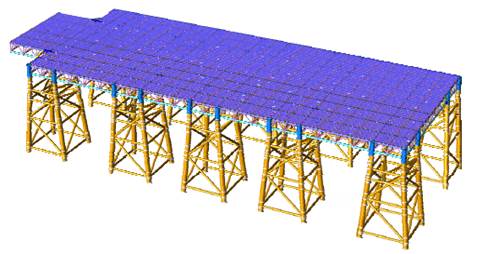
Figure 2.12 Mooring Dolphins / Walkways / Vent Stack Structural Jacket
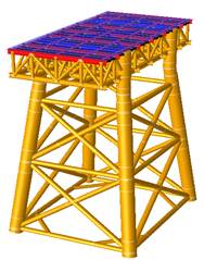
Preferred Substructure Design
Considering the reduced overall environmental impact and the reduced amount of piling needed, the Structural Jacket substructure is found to be a more suitable design for the Jetty, providing a stable structure for berthing and mooring the FSRU Vessel and the visiting LNGCs that deliver LNG to the LNG Terminal, and for the installation of the prefabricated topsides metering equipment, piping, cabling etc.
The Structural Jackets and their deck / topsides modules will be constructed in a fabrication yard that is likely to be outside of Hong Kong. The location of the fabrication yard will be determined during the implementation stage of the Project.
The pre-fabricated Structural Jackets will be transported to the Site of the Jetty, and then lowered into position on the seabed. Once in position on the seabed, the Structural Jackets will be fixed to the seabed by driving open-ended steel tubular piles through each leg of the Structural Jacket and for this purpose, some form of percussive piling will be required. Noise is generated by the percussive piling hammer which has its highest energy at lower frequency (20Hz to 1 kHz). Such noise has been identified to cause (short-term) behavioural reactions such as increased swimming speed in cetaceans ([36]). However, studies carried out in Hong Kong have determined that with the use of mitigation measures such as bubble jackets and bubble curtains, marine mammal behaviour does not change substantially during percussive piling operations ([37]).
A review was undertaken to assess the technically feasibility of the use of Bored Piles or Suction Piles to anchor the Structural Jackets to the seabed as an alternative to Friction Piling, the conclusions of the review are presented below.
Alternative Conventional Bored Piling Method
Bored Piles are ‘end bearing’ i.e. where the bottom end of a pile rests on bedrock i.e. the pile (or group of piles) acts as a column where the load from the Jetty marine structure is transferred through the bored piles to the strong bedrock.
The review of using conventional Bored Piling installed through the legs of the Structural Jackets concluded that this is not technically feasible due to the following reasons:
· Construction Risk – Due to the soft clay/sand seabed conditions, Bored Piles would require a steel casing to be installed first through the legs of each Structural Jacket to reach bedrock using a boring machine, therefore the legs and other connection elements of the Structural Jackets may be easily damaged. Should one leg or connection element be damaged, the whole Structural Jacket would need to be replaced. Hence the use of a Bored Pile for the installation of the Structural Jackets poses a major construction risk and is not technically feasible, nor is this installation method typically used.
· Depth of Bedrock / Installation Timing – Given that the bedrock depth is ~80-100m below the seabed, even it if were feasible to use Bored Piles, it would take much longer time to install them compared with open-end steel tubular piles which only need to be driven to a depth of around 60-70m below the seabed for load bearing purposes.
· Waste Generation – Again, even if it were feasible to use Bored Piles installation works will generate a substantial amount of waste water and marine sediment. Bored Piling would require considerable quantities of concrete to be transported by sea to the working area, and there is the potential for spillage. The management and control of such waste materials are challenging.
Consequently, considering the Bored Piles engineering challenges, the requirement to use multiple Jack-up Barge or temporary platforms resulting in more environmental impacts, the increase to marine traffic risks and waste generation/ sediment disposal, construction feasibility and a lengthier piling programme, Bored Piling is not deemed viable for this Project. It is noted that driving open-ended steel tubular piles would likely generate higher levels of underwater sound than Bored Piling, and the Project’s approach to mitigate the effects of underwater sound generated during open-ended steel tubular pile installation are discussed in the Preferred Piling Method Section below.
Alternative Suction Piling Method
The potential use of Suction Piles for the Jetty substructure was also considered. Suction Piles are not typically used for jetty construction and their use greatly depends on the seabed conditions at the Site of the Jetty, and due to the following concerns:
· Based on the lateral load analysis and the available information on the seabed conditions, the double-berth Jetty lateral movements which may be experienced by the Suction Pile foundations could be excessive and they are therefore unlikely to be a viable option; and
· Based on the seabed conditions, the Suction Piles would need to be approximately 36m tall and 7m in diameter. Installation of suction buckets starts with an initial penetration into the seabed by self-weight, followed by the application of suction (relative to seabed water pressure) within the caisson, which forces the remainder of the caisson to embed itself, leaving the top flush with the seabed. In this case, given a water depth of 15m and the suction bucket height of 36m, 20m self-penetration will need to be achieved before the caisson is submerged so that suction can be applied to the trapped water inside the bucket. However, based on the available seabed conditions information, the self-weight penetration for a 7m diameter suction bucket is assessed to be less than 20m.
Based on the above considerations, the use of Suction Piles is considered technically not feasible.
Preferred Piling Method
The use of Open-ended Steel Tubular Piles is recommended to be adopted for the Structural Jackets for the Jetty Substructure. Such an installation method is a tried and tested solution widely adopted successfully for offshore structures worldwide.
In terms of construction duration, it will take a significantly shorter period of time (~9 months) to complete the 80 piles required for the Jetty.
It is noted that there are environmental concerns over the noise generated by the installation of Open-end Steel Tubular Piles by percussive piling, therefore the following mitigation methods are proposed:
· Use of more environmental friendly piling method - hydraulic hammering (replace conventional diesel hammering);
· Use of Noise Reduction System for hydraulic hammering which is a well proven technique. Such system fully encloses the hammer and pile during driving. This proven technology can effectively reduce the airborne noise by 10dB to 18dB;
· Use of vibratory/ hydraulic pushing method to vibrate / push the pile for through the upper layer of the seabed (~70% in total pile length ) and only use the hydraulic hammer (if needed) to install the remainder of the pile length through the lower layer of the seabed (~30% in total pile length), therefore significantly reducing the percussive piling required and the associated noise impact from the hydraulic hammer; and
· Use of a bubble curtain at each piling location.
The above proposed conceptual design and construction options for the LNG Terminal Jetty substructure installation / construction methods will be fully assessed during the implementation stage of the Project in order to select the optimum installation / construction method based on the results of the seabed subsurface conditions from the Site Investigation, and ensuring that the required mitigation methods such as vibratory/ hydraulic pushing for the upper layer of the soil, using the bubble jackets and bubble curtains to reduce noise levels, and using the noise reduction system are included.
2.7.2 BPPS and LPS Pipelines
Subsea pipeline construction is a mature practice, and there are a number of available construction methods.
The BPPS Pipeline (30” diameter) and the LPS Pipeline (20” diameter) are subsea pipelines that are designed for high pressure gas transportation service based on stringent design standards.
The construction of these pipelines is also covered by stringent standards and codes of practice as it is critical to ensure that the pipelines are installed safely at the appropriate depth below the seabed, and are provided with the required pipeline protection to ensure that they are protected against any external, third party impact that may cause damage to the pipeline.
As such, the construction methods for the BPPS Pipeline and LPS Pipeline have to be carefully selected noting that the techniques / equipment available and the subsurface geotechnical conditions along the routes of both pipelines will have an impact on determining which construction methods are feasible, and those that are not.
The following subsea pipeline construction methods have been considered, and the findings are discussed below;
· Ploughing;
· Horizontal Directional Drilling (HDD);
· Dredging, both Grab Dredging and Trailing Suction Hopper Dredger; and
· Jetting.
Ploughing
Most ploughs are used for post-trenching. From an engineering perspective, the feasibility of ploughing depends on the sediment characteristics and seabed stability / conditions, since the plough (machine) is a heavy mechanical object and is not suitable for an unstable seabed. In particular ploughing is not suitable for the soft marine clay that is found on the seabed along the routes of the pipelines, since the plough sinks into the soft marine clay and the trench cannot be maintained open as the plough usually cuts a steeper slope.
Ploughing cannot provide sufficient depth for pipeline burial for armour rock protection, and there does not seem to be any precedence of the use of Ploughing for trenching to a depth of 3m.
Environmentally, ploughing is a non-dredged option which does not generate dredged sediments. The spread of suspended sediments generated by the plough is expected to be less than for a jetting machine. Compliance with Water Quality Objectives (WQOs) would need to be demonstrated.
Safety concerns may be the overriding issue as the pipelines may not be able to be ploughed to the required safe depth.
Therefore, Ploughing is not considered as a viable pipeline construction method for the Project due to the potential engineering constraints, thus this construction method option was not considered further in the EIA Report.
Horizontal Directional Drilling
Horizontal Directional Drilling (HDD) ‘Sea to Sea’ is a high technology approach with a high risk. HDD feasibility will need to be determined by sediment and geotechnical characteristics. The soft marine clay that is found on the seabed along the routes of the pipelines may not be suitable as it will be very difficult to maintain an open drill hole. Failure of the HDD operation due to the collapse of the drill hole may cause the loss of the entire pipeline string.
In addition, the large pipeline diameters of 30” and 20” will make the HDD operation extremely difficult, as the maximum distance for which HDD can construct / operate is quite short (~1.5 to 2km) therefore many intermediate working stations will be required along the pipeline routes. This would result in an increase in temporary habitat loss and disturbance from marine traffic associated with the intermediate working stations. This will also have a major impact on the costs of the Project.
Environmentally, HDD is non-dredged option which does not generate dredged material. However, HDD will generate spoil from the drilling operation that will need to be disposed of which could lead to potential waste management concern. Further, water quality impacts are also expected as large volumes of drilling mud required for drilling operations. While drilling mud can be contained, inevitable there will be release into suspension in the locality of the many drill holes and the many working stations.
Therefore, HDD is not considered as a viable pipeline construction method for the Project due to its technical challenges (which make its feasibility questionable), the HDD drilling operations will have significant environmental impacts, and costs constraints, thus this construction method option was not considered further in the EIA Report.
Dredging
There are two common dredging construction methods that are used for subsea pipeline construction in Hong Kong i.e. Grab Dredging and Trailing Suction Hopper Dredging (TSHD).
Each is available for the formation of the trenches required for the BPPS Pipeline and the LPS Pipeline. Following the formation (i.e. pre-forming) trenches by dredging, the pipeline will be laid and then rock armour can be placed in position.
The potential environmental benefits and dis-benefits of each dredging method are discussed below.
Grab Dredging
A grab dredger comprises of a rectangular pontoon on which is mounted a revolving crane equipped with a grab. The dredging operation consists of pre-forming the trench for the pipeline by lowering the grab to the seabed, then closing the grab, and raising the filled grab to the surface and emptying its contents into the loading barge moored alongside the grab dredger.
When the loading barge is full, the dredging operation is stopped while the loading barge is disconnected, and a replacement loading barge is connected so as to continue the dredging operations. The loading barge then transits to the designated sediment disposal area where the sediment is discharged. Then the loading barge returns to the dredging location and waits to replace the other loading barge, and commence another dredging cycle.
The grab dredging operation continues until the required length of pipeline trench is pre-formed.
Grab dredgers do not have their own propulsion system therefore they are towed into position by another vessel and then held on station by anchor moorings. Some grab dredgers have a spud or pile which can be lowered onto the seabed to secure the vessel during dredging operations.
Grab dredgers may release sediment into suspension by the following mechanisms:
· Impact of the grab on the seabed as it is lowered;
· Disturbance of the seabed as the closed grab is removed;
· Washing of sediment off the outside of the grab as it is raised through the water column, and when it is lowered again after emptying its contents;
· Leakage of water from the grab as it is raised above the water surface;
· Spillage of sediment from an over-full grab;
· Loss from a grab which cannot be fully closed due to the presence of debris; and
· Release by splashing when emptying a grab into the loading barge.
Studies in Hong Kong have, however, determined that with mitigation measures such as a silt curtain the release into suspension can be minimised.
During the transit of the loading barge to the sediment disposal site, sediment may be lost through leakage. However, dredging permits in Hong Kong include requirements that the loading barges used for the transport of dredged sediments shall have bottom-doors that are properly maintained and have tight-fitting seals in order to prevent sediment leakage.
Sediment may also be released into suspension when a loading barge discharges its sediment at the disposal sites. The amount of sediment that is released depends on a large number of factors including sediment characteristics, the speed and manner in which it is discharged from the loading barge, and the characteristics of the sediment disposal sites.
Notwithstanding that it generates sediment that requires disposal, grab dredging is considered to be a viable pipeline construction method for the Project, therefore it is considered further in the EIA Report.
Trailing Suction Hopper Dredging
A TSHD is designed to use a suction mouth at the end of a long tremie pipe to pre-form the pipeline trench. As the TSHD dredger moves along the pipeline route, the suction mouth trails along the seabed and sucks up the sediments. During the dredging operation the drag head will sink below the level of the surrounding seabed and the sediments will continue to be extracted and form the pipeline trench.
The main source of sediment release into suspension is the effect of the drag head when it is immersed in the sediment. The sediment release is generally lost to suspension very close to the level of the surrounding seabed.
During dredging operations the sediments are pumped into the TSHD dredger’s hopper and, when the hopper is fully loaded the dredging operations will be stopped and the TSHD dredger will transit to a designated sediment disposal area where it discharges the sediment, and then returns to the dredging location to commence another dredging cycle.
The dredging operation continues until the required length of pipeline trench is pre-formed.
A TSHD dredger does not use any anchors as it uses dynamic positioning. In comparison to a grab dredger, a TSHD dredger generally has a higher production rate.
Notwithstanding that it generates sediment that requires disposal, TSHD dredging is considered to be a viable pipeline construction method for the Project, therefore it is considered further in the EIA Report.
Jetting
As an alternative to dredging the BPPS Pipeline and the LPS Pipeline, jetting can be used to post-trench the pipelines to the required depth of cover, and then the rock armour can be placed in position. A description of jetting is presented below (jetty machines or mass flow excavators, a variance of jetting machines, are collectively termed “jetting machines” below as they are similar in nature).
A jetting machine can either be ‘self-propelled’ or be ‘towed’ by a barge. A ‘self-propelled’ jetting machine has wheels / tracks resting on the seabed and uses the pipeline for traction. Stability is achieved with the use of buoyancy aids.
The concept of using a jetting machine is based on fluidising the sediments on the seabed which allows the combined weight of the concrete coated pipeline to sink down to the required depth of cover.
Generally two or three passes are required to achieve the required depth of cover.
During the construction of the subsea pipeline using jetting technology, it is expected that sediment would be released into suspension close to the seabed and thereafter will settle out relatively quickly, therefore, the sediment would only be in suspension for a short period of time.
The significant environmental advantage of the use of jetting in pipeline construction works is that the method avoids the need to remove sediment from the seabed, and therefore avoids the need for sediment disposal.
Given that it does not generate any sediment that requires disposal, jetting is considered to be a viable pipeline construction method for the Project, therefore it is considered further in the EIA Report.
Preferred Construction Methods for the BPPS Pipeline and LPS Pipeline
It can be concluded from the above assessment that the preferred construction methods for the BPPS Pipeline and the LPS Pipeline are a combination of dredging (either grab dredging or TSHD dredging) or jetting.
However, as discussed in Section 2.4 and Section 2.5, the nature and topography of the preferred route for the BPPS Pipeline and the preferred route for the LPS Pipeline are very different, therefore the selection of the actual methods to be adopted for pipeline construction requires the detailed study of each pipeline route in order to identify the features along its length such as the in the proximity to existing / proposed marine parks, the distance from busy vessel fairways, the existence of other facilities such as existing subsea cables, etc. that will impact on the construction methods and the pipeline protection that is required at certain locations along the pipeline routes.
In addition, the selection of the actual methods to be adopted for pipeline construction also requires the detailed study of the environmental impacts. Considerations include the potential impacts to water quality during construction work (and consequent impacts on marine ecological resources and fisheries) and the volumes of dredged marine sediments that will require disposal.
In Section 3 information is provided on the findings of the engineering and marine studies that were carried out in order to select the construction methods that are proposed to be adopted for the BPPS Pipeline and the LPS Pipeline together with the associated pipeline protection measures.
In Section 7 and Section 8 information is provided on the results of the detailed environmental studies, in particular water quality modelling and waste management assessment, that were carried out to support the selection of the construction methods that are proposed to be adopted for the BPPS Pipeline and the LPS Pipeline.
The above engineering, marine and environmental studies focused on the analysis of the following:
· Data gathered during the EIA Study on marine ecological resources along the pipeline routes related to key sensitive receivers i.e. marine mammals (CWD and FP);
· Proximity to the existing Sha Chau and Lung Kwu Chau Marine Park and the proposed Southwest Lantau Marine Park and the proposed SLMP (noting that the proposed HKIA Marine Park will be designated after pipeline construction is complete);
· Construction methods impact on water quality; and
· Related marine sediment disposal requirements from dredging.
The aim of the above being to seek to achieve the most appropriate balance between the proposed construction methods where dredging produces sediment volumes that have to be disposed of, whereas jetting does not, but does produce temporarily suspended sediment that does impact on water quality.
The impact on water quality based on the use of the grab dredging, TSHD dredging and jetting options was reviewed as part of the EIA Study.
Water quality modelling results demonstrated that, under the working rate and working programme assumptions (detailed in Section 7 and Annex 7B), grab dredging methods did not result in any exceedance of the WQOs at sensitive receivers.
The spread of suspended sediment generated by a jetting machine or a TSHD dredger was, however, predicted to extend further and would be more concentrated than that generated by grab dredgers (for details see Annex 7C).
Therefore, in terms of potential water quality impacts, grab dredging has advantages in that it can be managed to meet the relevant assessment criteria. In addition, grab dredging has been widely adopted for pipeline pre-trenching in Hong Kong, therefore no engineering constraints are expected should this construction method be used. The disadvantage of grab dredging, however, is that the sediment generated needs to be disposed of at a designated area according to the sediment contamination classification.
It is important to recognise that existing capacity in Hong Kong for contaminated sediment disposal is very limited, therefore a reduction in the dredged sediment volumes is seen as highly advantageous to both the Project and to the HKSAR Government’s management of the limited capacity for contaminated sediment disposal.
As jetting does not generate any sediment that requires off-site disposal, the potential merit of the use of jetting for pipeline construction is thus considered as critical to the overall environmental acceptability of the Project.
Key Considerations
Along the shore approaches to the BPPS and the LPS, and at some segments of the proposed pipeline routes, the water depth is too shallow (sometimes only -3mPD) to utilise a TSHD dredger which typically has a draft of at least 5m.
For the segment of the BPPS Pipeline route in deeper waters i.e. at the Urmston Road and Southwest Lantau segments (at about -15mPD), it is considered possible to use TSHD.
Along the Urmston Road, West of Lung Kwu Chau and Southwest Lantau pipeline segments which traverse, or are adjacent to, designated fairways heavily trafficked by large marine vessels which require the highest level of pipeline protection from large anchor drop and drag, the use of jetting is not considered feasible from an engineering point of view because a jetted pipeline trench with armour rock protection cannot provide the required level of pipeline protection ([38]). However, the feasibility of using jetting for the construction of other pipeline segments has been investigated and confirmed to be viable.
Schedule Considerations
Post-trenching of the subsea pipeline by jetting offers a schedule benefit as generally the working rate is higher than that of a grab dredger, thus allowing the construction works to be completed in a shorter timeframe.
The use of a TSHD also presents similar schedule benefits since the dredging speed is also higher than that of a grab dredger. Overall, when the same daily working time is considered, grab dredging will result in the longest construction programme among the three proposed methods, but is acceptable to the project schedule.
Overall Considerations
· Minimizing the dredged sediment volumes is one of the key factors (alongside WQOs compliance and minimizing ecological impacts) for the overall environmental acceptability of the Project, hence where allowable in the context of WQO compliance and minimized ecological impacts, the use of jetting is preferred and the majority of the BPPS Pipeline and the LPS Pipeline routes are planned to be constructed by jetting. An added benefit is that the pipeline construction works may be completed in a shorter timeframe than using only grab dredging.
· Due to the requirement to provide the required level of pipeline protection (i.e. protection of anchor drop and drag from the large marine vessels passing the BPPS Pipeline route), the Urmston Road, West of Lung Kwu Chau and Southwest Lantau BPPS Pipeline segments cannot be construction by jetting, therefore these pipeline segment will be constructed by dredging.
· For dredging, it is considered that grab dredging and TSHD dredging would offer similar overall environmental performance and acceptability.
Taking all of the above into consideration, it was concluded that from an environmental perspective grab dredging, TSHD and Jetting appear to be suitable, the final selection to be made subject to detailed study of each pipeline route.
· Through optimisation of construction methods and minimisation of dredging along both BPPS Pipeline and LPS Pipeline, a combination of dredging and jetting is proposed with dredged sediment “in situ” volumes being significantly reduced to approximately 0.35Mm3.
Further details on the preferred pipeline construction methods are presented in Section 3.
2.8 Consideration of Construction Works Sequences
2.8.1 Pipeline Construction Sequencing
The water quality modelling results for the grab dredging and TSHD dredging have indicated that the pipeline construction works can proceed in either dry or wet season without there being appreciably different levels of impact.
From a marine ecological perspective it is noted that the density of sightings of marine mammals in the Northwest and West Lantau do not appreciably differ between seasons in the year (see Section 9). However, it has been noted that research on the CWD has indicated, based on stranding information, that in these two areas although calving occurs throughout the year the peak period would appear to be between March and August with the highest frequency in May and June ([39]).
The EIAO-TM specifies the priorities for addressing environmental impacts is avoidance and minimization. This philosophy was referred to in designing the marine works construction programme. It should be noted that reducing the overall duration of exposure to marine construction works by marine mammals is an effective approach to minimize impacts on these animals. Scheduling construction programme to avoid overlapping with the peak calving season of CWD in May and June or peak season of FP (December to May), restricting the daily maximum working hours, and implementation of a marine mammal exclusion zone by which marine works would cease temporarily whenever a marine mammal is sighted inside the zone are measures that will be adopted in this project as appropriate to achieve the purpose of impact avoidance and minimization.
Dredgers and jetting machines may need to operate on a 24 hours basis wherever practicable to shorten the overall duration of the pipeline construction works. This scheduling measure has been considered for jetting and dredging of the BPPS Pipeline and the LPS Pipeline routes where appropriate. To address environmental impacts, measures such as working time on a 12 hours basis only have also been considered where appropriate for pipeline jetting and dredging works.
Further, other activities associated with the pipeline construction, i.e. pipe-laying and the placement of armour rock protection may also operate on a 24 hour basis if appropriate and needed. Neither of these works activities is anticipated to cause adverse impacts to the marine environment.
2.8.2 Other Construction Sequences
The construction of the BPPS Pipeline and the LPS Pipeline and the construction of the LNG Terminal Jetty will be carried out concurrently. This is to ensure that the LNG Terminal Jetty is completed on time and the connections to the BPPS Pipeline and the LPS Pipeline are available at the required time.
The GRSs at the BPPS and the LPS are planned to be constructed independently of the BPPS Pipeline and the LPS Pipeline, with the connections being made once all Project components are complete. The construction schedule is discussed in further detail in Section 3.
2.9 Consideration of Options for System Design & Operational Modes
2.9.1 LNG Terminal
Regasification Process
On board the FSRU Vessel, the LNG is re-gasified by a simple heat exchange process. A “closed-loop” and “open-loop” regasification modes have been considered for the system design and operational mode. “Closed-loop” regasification utilizes heat transfer fluid such as propane, seawater or glycol-water. Within a closed-loop system, minimal water is required. “Open-loop” regasification utilizes seawater as the heating transfer fluid. Within an open-loop system, intake and outflow of seawater is required.
Closed-loop regasification is more commonly deployed today for usage in cold weather where the surrounding waters is too cold for using the open-loop regasification process, and the FSRU vessel will use internal boilers to heat up water and/or an intermediate fluid in a closed loop system. The “closed-loop” regasification mode is considered not preferable because:
· Propane, if used as a heat transfer fluid, will be required in a considerable amount. Propane is highly flammable and designated as a dangerous goods (DG) cargo. The closed-loop regasification system would require storing and using propane in close proximity to high pressure gas and LNG on board the FSRU Vessel which poses potential hazards to the FSRU Vessel and its operations as a result of increasing the explosion and fire risk. The use of propane in the industry for FSRU vessel regasification technology is being phased out and such systems are not readily available for the FSRU Vessel in the capacity required for this Project;
· Closed-loop utilising any intermediate fluid is less energy efficient for the regasification process, compared to open-loop. Large boilers to heat up water and/or an intermediate fluid in a closed loop system are very inefficient and consume larger amounts of fuel (around four times the amount for open loop regasification). There is also then a larger corresponding amount of increased emissions (e.g. NOx, CO2, etc.) from the FSRU vessel; and
· Due to the factors above, there is not a closed loop FSRU vessel available in the market today that provides the regasification capacity required for this Project.
Taking into consideration the above, the use of an open-loop regasification mode for the system design and operational mode is the preferred approach. The impacts of open-loop regasification have been analysed in detail in the Water Quality (Section 7), Ecology (Section 9) and Fisheries (Section 10) assessments.
Utilities Supply
On board supply of freshwater, sewage treatment, oily water separation, and power supply are considered for the system design and operational mode to be more environmentally friendly compared to off-site provision and supply of these utilities given off-site provision would contribute to additional infrastructure and marine vessel movements and associated emissions. On board supply of such equipment and utilities is a common practice for the shipping industry and oil and gas industry.
On board supply of such utilities is therefore considered to be preferable from an environmental perspective for the system design and operational mode, and therefore it is considered further in the EIA Report.
2.10 Scenarios With and Without the Project
With the Project in place, CLP and HK Electric are able to support the HKSAR Government’s policy to diversify the fuel mix for power generation and achieve the 2020 target of around 50% of power generation being from natural gas-fired units. The Project will also help to further reduce the air pollutant emissions from CLP and HK Electric’s power generation system, and further improve air quality and reduce carbon intensity.
With an increase in the need for additional gas supply in Hong Kong, the Project will help to provide adequate competitive gas supply capacity to CLP and HK Electric’s power generation system and accommodate the continued growth in electricity demand, the benefit of which is to ensure a reliable electricity supply.
No Action or Defer decision
Currently, CLP has to be reliant on its two existing pipeline gas sources, whereas HK Electric has to be reliant on its single existing pipeline gas source. If the Project does not proceed, CLP and HK Electric’s reliability and security of electricity supply could be at risk when one of these pipelines suffer a disruption. This impacts CLP and HK Electric in meeting the HKSAR Government’s fuel mix and environmental targets. Securing adequate competitive gas supply capacity to CLP and HK Electric’s power generation system to support the need for additional gas supply and continued growth in electricity demand would also be affected.
In addition, the supply capacity of CLP and HK Electric’s power generation system will reduce as a result of the progressive retirement of coal-fired generating units. Replacement gas-fired generating capacity and its gas supply need to be secured in time, otherwise CLP and HK Electric’s reliability of electricity supply and ability to meeting HKSAR Government’s environmental targets could be at risk. The long-term plan for the gradual replacement of power generated by coal-fired units with gas-fired units thus helping to further lower emissions from power generation would also be impacted.
With local gas-fired power generation set to increase from the 2015 level of 27% to the 2020 level of 50%, the Project is critical for ensuring a reliable supply of natural gas to fuel the BPPS and the LPS thereby meeting the HKSAR Government’s targets while maintaining Hong Kong’s electricity supply, where:
1. With the expected depletion of some of Hong Kong’s existing pipeline gas supplies, the long lead time and required to obtain additional gas supply, a key benefit of the Project is its ability to ensuring a timely availability of an additional gas supply, and the required infrastructure to import the additional gas.
2. Existing gas supplies via the three existing subsea pipelines from the Mainland are at risk of interruption should one of these pipelines suffer a disruption, particularly as these existing pipelines are not inter-connected, therefore there is the need to diversify Hong Kong’s gas supply options.
3. Electricity demand (and thus gas supply) is changing, while the existing pipelines have the capacity, the current contracted gas supplies are capped and provide limited flexibility to meet its future medium term and seasonal demand as these increase in line with the HKSAR Government’s policy to increase gas utilisation.
4. Hong Kong must present itself as an attractive option to LNG suppliers in the competitive LNG market, in addition to having comprehensive and advanced plans for developing the required LNG Terminal infrastructure which is advantageous to Hong Kong’s position.
The alternative of not importing additional gas supplies into Hong Kong and not creating the required infrastructure would significantly disadvantage CLP and HK Electric in that both companies would not be in a position to meet the HKSAR Government’s fuel mix policy and its aim to reduce carbon emissions would not be achieved. The policy objective of phasing down coal in tandem with increasing gas power generation would not be met. On the contrary, CLP and HK Electric would have to increase the use of coal to meet the future demand growth, which would lead to an increase in the emissions of NOx, SO2, particulates and carbon, until an additional source of natural gas is identified.
Further, if an additional gas supply source is not created together with the required LNG Terminal and pipeline infrastructure, this would put the CLP and HK Electric reliability and security of electricity supply at risk as CLP would have to continue to be reliant on its two existing pipeline gas sources, whereas HK Electric would have to continue to be reliant on its single existing pipeline gas source.
In summary, the absence of, or delay in the development of an additional gas supply for Hong Kong would not only entail an environmental impact, in the form of incremental emissions of NOx, SO2 and particulates, but would also compromise Hong Kong’s security and reliability of electricity supply.