Guidelines for the Design of Small Sewage Treatment Plants
GENERAL DESIGN CONSIDERATION |
| |
|
| 2.1 |
In order to ascertain the effluent quality requirements, a designer is encouraged to liaise with EPD by submitting the following information, prior to the design of STP:
- block and location plans of site;
- maximum number of persons (resident and non-resident) to be served;
- presence of shops, restaurants or other service trades;
- possibility of the need for future extensions to the plant;
- proposed location of discharge.
Based on such information, EPD will then formulate the required effluent quality standards.
|
| |
|
| 2.2 |
All elements of the STP should be open to view as far as possible for easy operation and maintenance. |
| |
|
| 2.3 |
Mechanical equipment which is critical to the functioning of the STP should be provided with on-line standby units. For example, an on-line standby pump at the equalization tank and an on-line standby chlorine dosing pump at the chlorination tank should be provided. |
| |
|
| 2.4 |
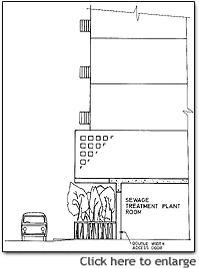
Entrance to the STP should be by a proper door without the use of steps or ladders and accessible by a vehicle. A second pedestrian entrance/exit should be provided as far as possible for emergency purposes at the opposite end of the plant room. |
| |
|
| 2.5 |
Due consideration should be given to the possible initial low flow condition before full population is achieved. A multiple of smaller units (with gate or other shut-off arrangements) should be provided as far as possible in lieu of a single large unit. |
| |
|
| 2.6 |
Excessive quantities of grease and oil may cause malfunction of an STP. In such cases, arrangements should be made where practicable for grease and oil to be removed at source. A properly designed grease trap should be provided where restaurants or garages are to be served by the STP. In general, a grease trap should be designed to provide a minimum water retention time of 20 minutes for all wastewater discharged from restaurant kitchens during peak flow periods. |
| |
|
| 2.7 |
Swimming pool filter backwash, if any, should be discharged to the STP for treatment. Design of the STP should take into account the flow and loadings of such wastewater. Pool water itself should however be drained to the stormwater system. |
| |
|
| 2.8 |
Under special circumstances, an autostart standby power generator may be required if it is considered that discharge of untreated wastewater to a specific water course is unacceptable even for a brief period during power failure. |
| |
|
| 2.9 |
An STP design submission should include, but is not limited to:
- key plan showing location of development and effluent discharge location;
- plan and section showing the location of STP within the development in relation to residential units and surrounding facilities;
- process and instrumentation diagrams;
- hydraulic profile together with supporting calculations;
- detailed process design calculation;
- detailed drawings with plan and elevation showing plant room layout, including pipework and equipment;
- route of access to the plant room and access within the STP;
- ventilation and lighting details;
- equipment schedule showing number of duty and standby units, make, model number, capacity etc. The schedule should be shown on the drawing;
- equipment catalogues and operation/maintenance manual.

|
(Text Alternative
|
|
     |