13
HAZARD
TO LIFE
13.1.1
Background
This section of the EIA presents a summary of
the analysis and findings of the Hazard to Life Assessment (also referred as
Quantitative Risk Assessment (QRA)) undertaken for the proposed East West Line
(TAW-HUH) Section of the Shatin to Central Link (SCL) project (the Project).
The Project consists of an 11 km extension of
the Ma On Shan Line from Tai Wai
Station, through Hin Keng,
Diamond Hill, Kai Tak, To Kwa
Wan, Ma Tau Wai, Ho Man Tin to Hung Hom. The Project involves nearly 9km to be constructed in
tunnel. The route will encounter a variety of ground conditions, urban and
rural environments, and a number of specific constraints in some localised
areas. The majority of the tunnelling will be by mechanical methods but there
will be blasting required in certain sections. Construction is expected to commence in 2012. Major civil works will be
completed by 2016, and all works will be completed by 2018.
The selection of
construction methods has been optimised to minimise, as far as possible, the
use of explosives depending on the type of material to be excavated. Only two
sections of tunnels will require excavation by Drill and Blast construction
method. These are:
·
Ho Man
Tin to Ma Tau Wai: The section of running tunnels between Shansi Street shaft and HOM Station is
proposed to be constructed as two single-track horse-shoe tunnels. This
approximately 480m long section of twin tunnels would be excavated within
granite using the drill & blast method; and
·
Ma Chai
Hang Ventilation Building to Hin Keng Portal: Drill & blast methods will be
used for the construction of a twin-track single tunnel for an alignment length
approximating 2450 m.
As shown above, a
substantial length of the tunnels and adits
(approximately 3.2 km of tunnels) will be excavated in rock. A significant
amount of explosives will be required for the construction of rock caverns,
tunnels and adits.
To enable a timely
delivery of explosives to site and in order to meet the proposed construction
work programme, one temporary Explosives Storage Magazine (Magazine) is
required. It will be located at Tseung Kwan O Area
137. The site was selected considering the distance to the work areas as well
as other constraints such as land availability, minimum separation distances
from temporary magazine to populated area, accessibility by Mines Division,
etc. (ref.1). With reference to the EIA Study Brief (ESB-191/2008),
if there is use of explosives for the construction activities and the storage
or blasting location is in close vicinity to populated areas, Potentially
Hazardous Installation site(s), town gas installations, and LPG Gas Stations
along the Project alignment a hazard to life assessment is required.
With reference to
the EIA Study Brief, some work areas will be located within the consultation
zone of a PHI namely the Shatin Water Treatment Works which stores chlorine in
one tonne drums. No work areas will be located in the consultation zone of Ma
Tau Kok Gas Production Plant or any other PHI. Based
on this and as required in the EIA Study Brief Section 3.4.5.4, the hazard to
life assessment for Sha Tin Water Treatment works has
been carried out for the construction and operational stages of the
Project. With reference to the
Study Brief Section 3.4.5.5, there is no storage, transport or use of
explosives within the consultation zone of the Ma Tau Kok
Gas Production Plant PHI either during the construction or operation stages of
the Project. Based on this, the Ma Tau Kok PHI
assessment is not considered applicable for this hazard to life assessment.
The QRA for the
storage, transport and use of explosives relates to the construction phase of
the project, in which blasting activities are expected. There will be no
explosives handled during the operational phase.
The Hazard to Life
assessment under this section of the EIA, addresses, in particular, the
following:
·
Storage
of explosives at the proposed temporary magazine (cartridged emulsion,
detonating cord and detonators) including handling of explosives within the
temporary magazine site;
·
Transport
of Explosives to the delivery points; and
·
Use of
explosives (cartridged emulsion, bulk emulsion manufactured at the blast site,
detonating cord and detonators) including handling of explosives from the
delivery points to the blast faces.
Further details of the QRA for the Project are presented in the Appendix
13.
·
Appendix 13A:
Hazard to Life Assessment for the Storage and Transportation of
Explosives from the proposed temporary Magazine to the delivery points;
·
Appendix 13B:
Hazard to Life Assessment for the Use of Explosives including the
explosive hazard impact assessment on PHIs and towngas facilities; and
·
Appendix 13C:
Hazard to Life Assessment for Shatin Water Treatment Works (STWTW)
covering the construction and operational stages on the Project.
The key legislation and guidelines that are
considered relevant to the development of the proposed SCL (TAW-HUH) project
are as follows:
·
Dangerous
Goods Ordinance, Chapter 295;
·
Environmental
Impact Assessment Ordinance (EIAO), Chapter 499; and
·
The EIA
Study Brief (ESB-191/2008), Section 3.2 and Section 3.4.5.
EIAO Technical Memorandum (EIAO-TM)
The requirement for a QRA of projects that involve
the storage, transport and use of dangerous goods where a risk to life is a key
issue with respect to the Hong Kong Government Risk Guidelines (HKRG) is
specified in Section 12 of the Environmental Impact Assessment Ordinance
Technical Memorandum (EIAO-TM).
The relevant authority for a QRA study relating to
a temporary explosives magazine storage facility and the transport of the
explosives is the Environmental Protection Department (EPD), as specified in Annex
22 of the EIAO-TM.
Annex 4 of the EIAO-TM specifies the Individual and
Societal Risk Guidelines.
Hong Kong Government Risk Guidelines (HKRG),
EIAO TM Annex 4
Individual risk is the predicted increase in the
chance of fatality per year to an individual due to a potential hazard. The
individual risk guidelines require that the maximum level of individual risk
should not exceed 1 in 100,000 per year i.e. 1 x10⁻⁵ per year.
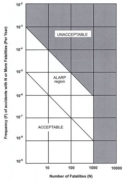
Societal risk expresses the risks to the whole
population. The HKRG is presented graphically in Figure 13.1. It is expressed in terms of lines plotting the
cumulative frequency (F) of N or more deaths in the population from incidents
at the installation. Two F-N risk lines are used in the HKRG that demark
“acceptable” or “unacceptable” societal risks. The intermediate region
indicates the acceptability of societal risk is borderline
and should be reduced to a level which is “as low as is reasonably practicable”
(ALARP). It seeks to ensure that all practicable and cost effective measures
that can reduce risk will be considered.
Figure
13.1 Hong Kong Government Risk
Guidelines
The objective of the
QRA study is to assess the risk to life of the general public from the hazards
that arise from the storage, transport and use of the explosives that are
required to facilitate the construction of the Project. The results of the QRA
should then be compared with the HKRG.
The detailed
requirements of the study are given in Section 3.4.5 of the EIA study brief.
The main QRA requirements for the storage, transport and use of explosives are:
·
To
identify hazardous scenarios associated with the storage, transport and use of
explosives; and possible damage scenarios to the gas installations leading to
catastrophic and non-catastrophic failures of the gasholder causing gas
release; and then determine a set of relevant scenarios to be included in a
QRA;
·
To
execute a QRA of the set of hazardous scenarios determined, expressing
population risks in both individual and societal terms;
·
To
compare the individual and societal risks with the Criteria for Evaluating
Hazard to Life stipulated in Annex 4 of the EIAO-TM; and
·
To
identify and assess practicable and cost-effective mitigation measures (e.g.
selection of the shortest practicable road transport routes to and from the
storage facility etc.).
The methodology of the hazard assessment should be consistent with
previous studies having similar issues.
The elements of the QRA are shown schematically in Figure 13.2. It includes the following:
·
Collection
and review of relevant data for the proposed Magazines, the transport from the
magazines, and the use of explosives at the works area, as well as population
and vulnerable receptors, such as slopes, retaining walls etc., in the vicinity
of storage, the tunnel construction and proposed transport routes;
·
Hazard
identification. A structured study involving a “what-if” analysis and a review
of literature and accident databases were undertaken and updated. These formed
the basis for identifying all the hazardous scenarios for the QRA study;
·
Frequency
estimation. The frequencies, or the likelihood, of the various outcomes that
result from the hazards associated with the storage and transport of explosives
was taken primarily from the ERM 2009 study (ref. 26), which has been accepted
by the relevant authorities. The ERM 2008 study (ref. 2) was the primary reference for the hazard assessment
related to the use of explosives at the work areas. Where necessary, to
consider specific factors applicable for the Project, recent accident
statistics, and to reflect the current knowledge on the explosives’ properties,
these frequencies were modified or updated making reference, as far as possible
to published references; such as the previous Hong Kong studies , UK HSE, US
DoD, Dutch TNO, latest accident statistics from the Transport Department and
Fire Service Department, etc.;
·
For all
identified hazards, the frequency assessment has been documented and the
consequences were modelled;
·
The
frequency model related to the transport and storage of explosives was taken
from the ERM 2009 study (ref. 26). The frequency model related to the use of
explosives was taken from the ERM 2008 study (ref. 2) but with human factor study and Fault Trees updated
to reflect the particular conditions of SCL (TAW-HUH) such as blast face areas,
number of sectors at the work face, number of production holes and Maximum
instant Charge (MIC) per production hole.
·
The
consequence models employed in this study were :
- Blast effects including overpressure, flying
debris, fireball, etc.: the ESTC model (ref.3), developed by the UK Health and Safety Commission
(HSC). Although, there have been a number of recent studies suggesting that the
ESTC (2000) models should be reviewed for applicability to explosive stores and
transport, these models are still the recommended models in the UK and adopted
in the ERM 2008 study (ref. 2);
- Ground shock/vibrations generated from an
explosion: Ground vibration models developed as part of the WIL methodology
(ref. 2). Key sensitive receivers were preliminarily screened
based on the threshold limits of Peak Particle Velocity (PPV), i.e. PPV ≥
90 mm/s (for slopes), PPV ≥ 100 mm/s (for buildings), PPV ≥ 13 mm/s (for gas
offtake stations) and PPV ≥ 25 mm/s (for gas pipes). and PPV ≥ 13 mm/s for historical
structures and other structures that may have a lower standard of design. A detailed QRA was
then conducted as per the WIL methodology (ref.2) for those features with PPV exceeding the threshold
levels.
- Gas piping failure arising from an explosion
scenario: gas release occurring from an explosion scenario and subsequent
possible hazardous outcomes such as fireball, jet fire and flash fires were
modelled using a traditional QRA approach consistent with a number of previous Hong Kong studies for gas installations (details are
provided in Appendix 13B).
·
The
consequence and frequency data were subsequently combined using ERM’s in-house
proprietary software Riskplot TM to produce the required risk estimates. The
transport part of the risk assessment, consistently with the ERM 2009 study
(ref. 26), uses an in-house Explosive Transport GIS Risk Assessment tool
(E-TRA) developed to account for three-dimensional blast effects on buildings
and the effect of accidental explosions on elevated roads. It also accounts for
traffic jam scenarios which could occur in some accidental scenarios as
reported in ref.4. The E-TRA model is summarised in Section 3.2 of Appendix 13A and has been validated against Riskplot TM.
Finally, the results from the risk assessment were compared to the
EIAO-TM Criteria. Recommendations have been made where required to ensure
compliance with EIAO-TM Criteria, relevant best practice, and to reduce the
overall risk levels.
Figure 13.2 Schematic Diagram of QRA Process
The methodology used
in this hazard assessment is consistent with previous studies. Details of the
analysis can be found in Appendix 13A and 13B.
13.5.1 Project Overview
The Project
comprises the following key elements:
·
Interfaces
with existing stations such as Tai Wai Station, Diamond Hill Station, Hung Hom
Station;
·
Interfaces
with other railway extensions such as Kwun Tong Line Extension (KTE) at Ho Man
Tin Station (part of KTE project);
·
New
stations including Hin Keng Station, Kai Tak Station, To Kwa Wan Station and Ma
Tau Wai Station;
·
Railway
alignment sections including:
- Hung Hom to Ho Man Tin: This section of tunnel will
connect between the Winslow Garden portal and Ho Man Tin Station. It will be
constructed by cut & cover method;
- Ho Man Tin to Ma Tau Wai: The section of running
tunnels between Shansi Street
shaft and HOM Station is proposed to be constructed as two single track
horse-shoe tunnels. This approximately 480m long section of twin tunnels would
be excavated within granite using the drill & blast method;
- Ma Tau Wai to To Kwa Wan: The tunnels will be
constructed with twin bored single track Tunnel Boring Machine (TBM) drives to be
launched at the southern end of TKW Station and retrieved at the Shansi Street
Shaft to the south of MTW Station;
- To Kwa Wan to Kai Tak: The tunnel in this section
will be constructed in open cut with battered side slopes;
- Kai Tak Diamond Hill: From Kai Tak Station to Prince Edward Road East
approximately 400m of tunnel will be constructed by cut & cover method,
including a launching shaft for a TBM to construct the tunnels towards Diamond
Hill Station;
- Diamond Hill to Ma Chai Hang Ventilation Building: Excavation
here would start with open cut methods, followed by cut and cover and
eventually use of a TBM;
- Ma Chai
Hang Ventilation
Building to Hin Keng
Portal: Drill & blast methods to be used, although at certain sections at
reduced rates due to vibration restrictions (sensitive receivers);
- Hin Keng Portal to Tai Wai Station: A viaduct will
be constructed from the Hin Keng Portal to Hin Keng Station. The alignment will
continue on elevated tracks up to Tai Wai Station;
- Shafts will be mechanically excavated.
The proposed Project
alignment and work areas are shown in Figure 13.3.
Construction is
expected to commence in 2012. Major civil works will be completed by 2016, and
all works will be completed by 2018. Excavation in rock by blasting will be
ongoing generally from October 2013 until March 2015 for a significant length
of the tunnels and adits (approximately 3.2 km).
For the purpose of
this study, the alignment is divided into two areas:
·
Lion
Rock tunnel from Ma Chai Hang Ventilation Building to Hin Keng portal:
approximately 2450 m long twin track tunnel; and
·
Ho Man
Tin tunnels from Shansi Street
shaft to Ho Man Tin station interface: approximately 480 m long twin (two)
single track tunnels.
Two categories of explosives will be used for the construction of tunnel
by Drill and Blast methods. These are:
·
Initiating
explosives: cartridged emulsion explosives, detonating cord and detonators; and
·
Blasting
explosives: bulk emulsion explosives manufactured at the blast site or, in
close proximity to sensitive receivers (i.e. with MIC less than 2 kg),
cartridges emulsion explosives.
Cartridged emulsion and detonating cord will be delivered
from the temporary explosives magazine to the various construction sites by the
appointed contractors using Mines Division licensed trucks. These explosives
are classified as an explosive Class 1.1D under United Nation (UN)
Classification (ref.8) and as a Category 1
(Explosive and blasting agents) Dangerous Goods under the Hong Kong Dangerous
Goods Ordinance.
Detonators will also
be used to initiate the blast at the working face. As used in this project,
they are classified as Class 1.4B or 1.4S explosives under the UN
classification system and Category 1 (Explosives and Blasting Agents) under the
Hong Kong Dangerous Goods Ordinance, and will be transported from magazine to
work areas by a dedicated truck, which is identical to, but independent of the
truck carrying the emulsion explosives and detonating cord. Detonators approved
for use in Hong Kong are of the Non-Electric
Type, i.e. initiated by shock tube.
Explosives
classified as Class 1.1 is defined as substances and articles which have a mass
explosion hazard while Class 1.4 explosives present no significant hazard
outside the packaging. To comply with the classification, it is required to
ensure that the explosive is safe to transport, to pass a series of
classification tests in accordance with the UN test manual, 2009 (ref.7). Due to different properties of explosives, a
compatibility class is also assigned, as applicable to this Project. Type “B”
is defined as “An article containing a primary explosive substance and not
containing two or more protective features” and type “S” is defined as “The
substance or article so packed or designed that any hazardous effects arising from
accidental functioning are limited to the extent that they do not significantly
hinder or prohibit fire fighting or other emergency response efforts in the
immediate vicinity of the package”.
Bulk emulsion
precursor will be transported to the blast sites by the appointed third party
supplier. It is classified as an oxidising agent Class 5.1 under the UN
Classification system and as Category 7, i.e. strong supporter of combustion
under the Hong Kong Dangerous Goods Ordinance. Prior to sensitizing, it is not
considered as an explosive, and hence outside the scope of this QRA. Bulk
emulsion will not be stored within the temporary magazine.
13.5.2 Statutory/ Licensing Requirements
The statutory / licensing
requirements with respect to the explosives (Cat. 1 Dangerous Goods) or the
oxidizing substances (Cat. 7 Dangerous Goods) used to prepare explosives at the
construction work area as well as relevant government departments/ authorities’
advice and practice on the proposed transport and storage of explosives for the
blasting activities are summarized below.
Category 1 Explosives and Blasting Agents
·
Responsible
authority: The Commissioner of
Mines
·
Applicable
regulations/ guidance notes:
- Supply of detonators and cartridged emulsion
explosives (under the Dangerous Goods (General) Regulations Cap. 295B);
- Approved explosives for blasting in Hong Kong (under the Dangerous Goods (General)
Regulations Cap. 295B);
- Blast design (under the Dangerous Goods (General)
Regulations Cap. 295B);
- Blast loading and execution (under the Dangerous
Goods (General) Regulations Cap. 295B);
- Removal of explosives (under Regulation 4 of the
Dangerous Goods (General) regulations Cap. 295B);
- Approval of an explosives delivery vehicle (under
CEDD’s “Guidance Note on Requirements for Approval of an Explosive Delivery
Vehicle” (ref.9));
- Explosive delivery vehicle design features and
safety requirements (under CEDD’s “Guidance Note on Requirements for Approval
of an Explosive Delivery Vehicle” (ref.9);
- Explosive magazine (under CEDD’s document “How to
Apply for a Mode A Explosives Store Licence” (ref.10));
- Explosives produced at site (under Regulation 31A
of the Dangerous Goods (General) Regulations Cap. 295B); and
- Explosives load per truck (in accordance with the
Removal Permit under the Dangerous Goods (General) Regulations Cap. 295B).
Category 7 Strong Supporters of Combustion
·
Responsible
authority: Fire Services Department
·
Applicable
regulations:
- Storage of oxidizing agents (under Dangerous Goods
(General) Regulations Cap. 295B)
This Project will
use cartridged emulsion explosives as initiating
explosives. For blasting explosives, bulk emulsion will be used; however,
cartridges emulsion explosives may be used as blasting explosives in close
proximity to sensitive receivers. Therefore, the storage and transport
requirements for explosives are the minimum required quantities for the
Project.
13.5.3 Temporary Storage Magazine Details
A temporary magazine
site is proposed to be built at Tseung Kwan O Area
137. The design, construction and operation of the temporary magazine will
comply with the general requirements from the Commissioner of Mines (ref.10).
The temporary
magazine is generally designed to store sufficient quantities of explosives for
two days so as to allow blasting to be carried out 24 hours per day and provide
a buffer in the event of delivery interruption to the temporary magazine by
Mines Division. However, there will be periods during peak
explosives requirements where one day storage capacity is
envisaged. If storage capacity is not able to satisfy demand on a
specific day, direct delivery by Mines Division can be requested, or a blast
can be rescheduled until the following day when the magazine stores are
replenished.
The temporary
Magazine is required to serve the delivery points at Ma Chai
Hang (MCH) Ventilation
Building, Shansi Street
Shaft and Hin Keng Portal.
Potential magazine site locations in Hong Kong
close to the blasting locations have been investigated. The site at Tseung
Kwan O Area 137, although remote from the work areas, has been retained as the
only practicable site candidate meeting Mines Division separation distance
requirements. It is in a remote area with no public access nearby and is very
convenient for the Mines Delivery with a pier nearby for deliveries.
The temporary
Magazine comprises 4 stores each capable of storing 250 kg of explosives. A
storage chamber for detonators equivalent to two days
supply is provided next to each explosives chamber. The detonators have a very
low explosive mass and contain less than 1 gram of high explosives per
detonator. The net explosive quantity within each detonator chamber will be
less than 2 to 3 kg. The temporary magazine site at Tseung
Kwan O Area 137 will also be used for the KTE project with the SCL (TAW-HUH)
stores located adjacent to the dedicated KTE explosive stores. The four SCL
(TAW-HUH) stores will be dedicated to this Project.
The work areas and
the associated explosives using contract packaging for the temporary magazine
are shown in Table 13.1. The quantities (kg) of explosives
mentioned in the report are represented in gross weight, unless they are
clearly specified as TNT eqv. kg.
Each of the magazine
buildings is a single-storey, detached and bunded structure,
which is fenced and secured in accordance with the Commissioner of Mines’
requirements. Details of the requirements are defined in the CEDD document “How
to Apply for a Mode A Explosives Store Licence” (ref.10). Surface road access suitable for 11-tonne trucks is
also provided for delivery of explosives.
Table 13.1 Project Contracts and Work Areas
(Blasting only)
|
Contract No.
|
Storage Magazine
|
2 Day Explosive Storage Requirement
per contract
|
Delivery Point (Work Area)
|
|
Lion Rock Tunnel (MCH to HIK)
|
TKO Area 137
|
500 kg (2x250kg stores)
|
MCH
Road
(Ma Chai
Hang Ventilation Building)
|
|
Hin Keng
Estate Access Road (Hin Keng Portal)
|
|
Ho Man Tin Tunnels
|
TKO Area 137
|
500 kg (2x250kg stores)
|
Shansi
Street
(Shansi Street
Shaft)
|
13.5.4 Transport Route Details
Mines Division will deliver
explosives by the shortest practicable route to the temporary Magazine on a
daily basis (once per day), from where explosives will be transferred to the
work areas by the contractors for the daily or twice-daily blasts depending on
requirements for construction. Loads will be limited to a maximum of
200 kg per truck or less in accordance with the Removal Permit issued by
Mines Division.
The explosives will
be delivered to the various construction work areas using the public roads as
shown in Figure 13.4. The proposed delivery points from the temporary
magazine are shown in Table 13.1.
According to the
current construction programme, delivery of explosives to the three delivery
points will be required from late 2013 to early 2015. The delivery programme to
each work area will overlap significantly.
In addition to cartridged emulsion and detonating cord, detonators will
also be transported. Detonators will be transported in a separate and dedicated
licensed vehicle.
The licensed
explosives delivery vehicles (LGV pick-up trucks) for delivery of explosives
from the temporary site magazine to the worksites, used as the basis for this
QRA, will have the following safety features:
·
Diesel
powered;
·
Driver’s
cabin is separated by a distance of not less than 150mm from the cargo
compartment of the vehicle;
·
Manual
fuel isolation switch;
·
The
exhaust system is located as far from the cargo compartment as possible. The
modification of the exhaust system will be approved by the Transport Department;
·
All
electrical wiring or electrical devices will be shrouded in fire resisting
conduits;
·
Fuel
tank will be protected from accidental damage, and designed to prevent
accumulation of spilt fuel on any part of the vehicle;
·
The
required number of fire extinguishers shall be agreed with Mines Division;
·
Fire
resistant material will be fitted between the wheel arches and the goods
compartment;
·
Hand-held
lightning detector provided in the vehicle for lightning detection during
loading and unloading of explosives;
·
Lockable
wood lined steel or aluminium receptacles mounted on the vehicle tray; and
·
Fold
down / up explosives warning signs and red strobe beacons.
In addition, a fire screen will be fitted between the cab and the load
compartment and between the load compartment and the chassis.
13.5.5 Use of Explosives Details
Explosives will be
used for the construction of the Lion Rock tunnel and the Ho Man Tin tunnels.
The initial excavation
of the tunnels will be by mechanical methods. Drill and blast excavation will
then be adopted for about 10 m for trial blasting, followed by full face
excavation if ground conditions are suitable. Blasting cover protection will be
provided to all shaft/portal prior to blasting being carried out.
The following
safeguards will be implemented during blasting.
Vibration Monitoring. It is a requirement to
monitor every blast in Hong Kong to record
blast induced ground vibrations. A blasting engineer is responsible for
ensuring that the controlling and other nominated sensitive receivers for each
blast are monitored to record the vibration levels in terms of Peak Particle
Velocity (mm/sec).
Trial Blasts. Trial
blasts will be carried out for the first series of blasts for the tunnels and
different areas or sectors of the project if required. The trial blasts will be
used to demonstrate that the different types of blasting are safe, and the
blasting monitoring and control procedures are effective. The trial blasts are
conducted with cartridged emulsion explosives.
Advance Notice of
Blasts. As part of the process of issuing a License to Possess and a Permit to
Use dangerous goods, Mines Division will require that highly visible warning
notices/signs be posted at several locations to warn the public that blasting
will take place. These warning signs will be posted near the intended blasting
location, even though all blasts will be conducted underground. The Contractor
is required to write the blasting date and time on the notice.
Contractors are
required by Law to have a comprehensive Safety Management System and this is
implemented and supervised by on-site safety teams. Independent third party
auditors make annual checks of documentation and safety records.
13.5.6 Base Case and Worst Case for
Quantitative Risk Assessment
The actual
construction programme will depend on the detailed design and appointed
contractors. It may also depend on the actual achievable progress rates which
may vary due to specific site conditions (e.g. geology). To consider the
uncertainty in the envisaged construction programme, a Base Case, which
accounts for expected programme variations, and a Worst Case, which presents
the worst programme scenario, have been considered for
the assessment.
Base Case Programme for Hazard to Life Assessment
Based on the
envisaged construction programme and sequence of works, the annual travel
distance by explosive vehicles, carrying cartridged
emulsion and detonating cord, will reach a peak in the period between December
2013 and November 2014, with an annual number of deliveries of 1,127 and a
travel distance is around 28,000 km. This period is referred as the peak
explosive delivery period which is taken to represent the Base Case scenario
for the Hazard to Life Assessment. The delivery frequency has been estimated on
the basis that, for a given delivery point, each delivery will be made to each
blast face independently of the other blast faces even if the load could be
transported on the same truck. This approach, although slightly conservative,
accounts for expected delivery variations during the peak delivery period,
within which, separate deliveries will be generally undertaken.
The total number of
trips has been estimated based on the typical licensing limit of 200 kg
explosives per truck.
In the Base Case, it
was considered that blasting could be carried out at predetermined time during
the day following the envisaged construction programme. A distribution of
delivery time has thus been considered based on the construction programme.
The Base Case
programme is summarized in Table 13.2.
Table 13.2 Summary of Explosives Deliveries
and Transport Quantities (for Base Case)
|
Delivery Point
|
Explosive Deliveries in Peak Delivery
Period (trips/y)
|
Peak Transport Quantity (kg/trip)
|
|
|
|
MCH Ventilation
Building
|
513
|
162
|
|
|
Shansi St Shaft
|
334
|
200
|
|
|
Hin
Keng Portal
|
280
|
200
|
|
|
Total
|
1127
|
-
|
|
Worst Case Programme for Hazard to Life Assessment:
The Hazard to Life
Assessment also covers the Worst Case scenario. It addresses the possibility
that, due to construction uncertainties or contractors’ methods of working, the
contractors propose an actual construction programme which differs from the envisaged
construction programme. Such a case may result in a higher number of delivery
trips. Return trips loaded with explosives will generally be avoided; however,
due to some construction uncertainties, a number of return trips could be made.
Overall, in the worst case, a 20% increase in the number of deliveries compared
to the base case scenario may result based on previous project experience.
In this project, for
a particular delivery point, it is possible that the explosive load required
for each delivery will be higher than that indicated in the envisaged programme
due to particular site conditions and blasting requirements; however, the
explosive load to be transported will be, as a worst case, the maximum
explosive load for the site (sum of the loads for each blast face within the
same work site). The delivery load, in the Worst Case Scenario, has been
selected as the sum of the loads for each blast face within the same work site
bearing in mind the licensing limit of 200kg for the truck.
In this Worst Case
Scenario, explosives could be delivered at peak day times.
The Worst Case
programme is summarized in Table 13.3.
Table 13.3 Summary of Explosives Deliveries
and Transport Quantities (Worst Case)
|
Delivery Point
|
Explosive Deliveries in Worst Case
(trips/y)
|
Transport Quantity (kg/trip)
|
|
MCH Ventilation
Building
|
616
|
162
|
|
Shansi St Shaft
|
401
|
200
|
|
Hin
Keng Portal
|
336
|
200
|
|
Total
|
1353
|
-
|
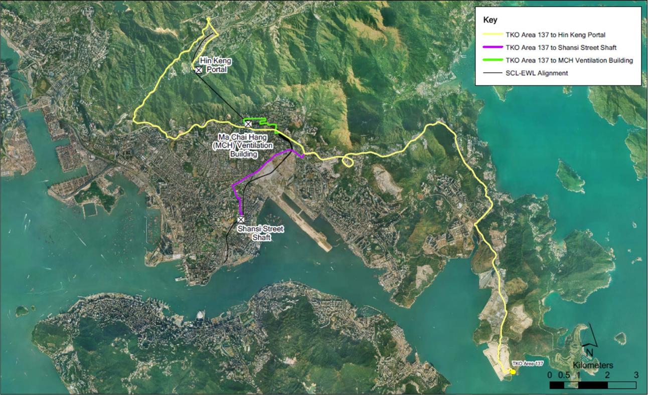
Figure 13.3 Proposed Alignment
and Work Areas
Figure
13.4 Project Alignment, Proposed Magazine Location and
Explosives Transport Routes
Population within
the vicinity of the temporary explosives magazine is estimated based on site surveys
and information gathered from Geographic Information
System (GIS) database 2007/2008 data (ref.11) and aerial maps. There are
no known (current or future) buildings or any other structures in the hazard
zone of the proposed temporary Magazine.
Population data used for the transport risk
assessment have been collected by a combination of site survey, Base District
Traffic Model (BDTM) 2011, Annual Traffic Census 2007 (ref.12), Road Traffic Accident Statistics 2007 (ref.13&14), Centamap (2009) and GIS
tools. For areas where information is not available, assumptions have been used
consistently with the previously approved studies. Three types of population
have been considered.
·
Pedestrian
population on footpaths and pavements next to delivery routes;
·
Road
population; and
·
Building
population.
The approach to modelling
the risks during transport of explosives is fully 3-dimensional and GIS based.
It also accounts for the potential increased risk when explosives trucks travel
on elevated roads.
The population data adopted in the QRA is detailed
in Appendix 13A.
Hazard identification consisted of a review of the
following:
·
Explosives
properties;
·
Scenarios
presented in previous relevant studies;
·
Historical
accidents; and
·
Discussions
with explosives and blasting specialists.
13.7.1 Hazards of Explosives
Explosives present a hazard to both property and
people. This hazard manifests itself in the following ways:
·
Blast
and pressure wave;
·
Flying
fragments or missiles;
·
Thermal
radiation; and
·
Cratering
and Ground shock.
In the case of explosions, the biggest damage is
usually caused by the blast effects. The blast and pressure waves can cause
injury to sensitive human organs such as the ears and lungs. However,
considerable overpressures are required for fatalities to occur, and
consequently people need to be fairly close to the scene of the direct
explosion effects to be significant.
Other effects due to the blast or overpressure are associated
with damage to buildings and other structures/ objects or the impact of debris
and fragments from damaged building structure, and the vehicle or container in
which the explosives are held. Moreover, injury may occur when people are
displaced or swept away, or due to the violent movement of internal organs
within the body.
An explosion may result in the formation of a short
duration fireball since the fuel content of the emulsion is oxidised.
However, although it is generally the case that the thermal hazards from an
explosives detonation event is of less concern than the blast and fragment
hazards.
13.7.2 Review of Incidents
A review of reported safety incidents involving
storage, transport and disposal of explosives (in industrial applications) was
carried out. Records were retrieved mainly from the UK Health and Safety
Executive (UK HSE)’s Explosives Incidents Database Advisory Service (EIDAS)
(ref.15), US Mine Safety and Health Administration (MHSA)
(ref.16) and Western
Australia’s Department of Consumer and Employment
Protection (DOCEP) (ref.17). The records provided are
also supplemented with information obtained from various sources. An analysis
of accident data is provided in Section 5 and Section 6 of Appendix 13A.
13.7.3 Scenarios for Hazard Assessment
The following table (Table 13.4) provides a
summary of the scenarios considered in this QRA.
Table 13.4 Scenarios
Considered in the QRA study
|
Tag
|
Scenario
|
|
Storage
of Explosives
|
|
ST01
|
Detonation of full load of
explosives in one store in the TKO Area 137 magazine site
|
|
ST02
|
Detonation of full load of
explosives in one contractor truck on the access road within TKO Area 137
magazine site boundary
|
|
Transport
of Explosives
|
|
ST03
|
Detonation of full load of explosives
in one contractor truck on public roads – from TKO Area 137 site to MCH Shaft
delivery point
|
|
ST04
|
Detonation of full load of
explosives in one contractor truck on public roads – from TKO Area 137 site
to Shansi Street
delivery point
|
|
ST05
|
Detonation of full load of
explosives in one contractor truck on public roads – from TKO Area 137 site
to Hin Keng Portal
delivery point
|
|
Use
of Explosives
|
|
U01
|
Higher than expected vibrations
generated at the blast face due to human errors or other reasons such as
manufacturing defects causing deviation from the confirmed design
|
|
U02
|
Vibrations due to the detonation of
a full load of explosives within the tunnel whilst transferring explosives to
the appropriate blast site. As per WIL study (ERM, 2008), vibrations may be
generated at the truck location due to an uncoupled explosion.
|
|
U03
|
Blast effects including debris and
overpressure due to the detonation of a full load of explosives within the tunnel.
Blast effects are modelled at the shaft/portal
ignoring decay factors along the tunnel.
|
|
U04
|
Blast and vibration effects due to
accidental explosion of the full load of explosives while transferring explosives
from the delivery points to the shafts/portals
|
Deflagration or
detonation explosion may occur during the transportation of explosives from the
temporary magazine to the construction sites. This accidental explosion can be caused
by spontaneous fire (non-crash fire), fire after a vehicle crash (crash fire),
impact initiation in crash (crash impact) or spontaneous explosion during the
normal condition of transport which may occur if the cargo load contains
‘unsafe explosives’.
In this study, a fault tree has been developed to
assess the overall explosion frequency as applicable to the Project
contractors’ trucks based on the latest information available on the explosives
properties, vehicle incident frequencies provided by the Transport Department
and Fire Services Department, and the specific explosive transport vehicle
design and operation to be used as part of the Project. The details of the
frequency assessment are provided in Section 6 of Appendix 13A.
13.8.1 Frequency analysis for Transport of
Explosives
Based on Hong Kong
vehicle accident data, the frequencies of explosives initiation during road
transport are estimated as 7.69 x 10⁻¹⁰/km for the
truck on non-expressway and 6.87 x 10⁻¹⁰/km on expressway, using a fault tree
approach. The fault tree model has considered the frequencies of non-crash
fire, crash fire, crash impact and unsafe explosive. Adjustment factors were
applied to the model to account for the probabilities of explosive initiation
due to thermal stimulus or crash impact.
13.8.2 Frequency analysis for Storage of
Explosives
The overall
initiating event frequency within the temporary storage magazine is based upon
the UK HSE recommended value of 1 x 10⁻⁴ per storehouse year. Additional risk
due to manual transfer of explosives, lightning strike, aircraft crash, hill/
vegetation fire, earthquake and other site specific considerations to the SCL
(TAW-HUH) project were also considered but their contribution was negligible
(see Section 6 of Appendix 13A).
13.8.3 Frequency analysis for Use of
Explosives
A failure mode analysis was carried out to
determine the potential failure modes associated with the use of explosives,
leading to higher vibration. The scenario of 2 or more maximum instant charges
(MIC) detonated at the same time was identified for the risk assessment. Fault
tree analysis was conducted, in conjunction with human factor assessment to
determine the occurrence frequency of 2 or more MIC detonated at the same time
(see Section 4 of Appendix 13B).
Table 13.5 summarises the overall frequency for failure scenarios
leading to higher than expected vibrations for the whole SCL (TAW-HUH) project.
The blast linear length refers to the total pull length by the drill and blast
operation. For the SCL (TAW-HUH) alignment, the blast linear length includes
the Lion Rock Tunnel and the Ho Man Tin tunnels
For the Worst Case scenario, the overall number of
blasts is increased by 20% to account for potential deviation from the
envisaged construction programme.
Table
13.5 Overall Frequency for Failure Scenarios
leading to Higher Vibration for the Whole Project Phase (Scenario U01 in Table 13.4)
|
Sections
|
Total Blast
Linear Length
|
Occurrence Frequency for multiple MIC detonated
at the same time (Occurrence for the whole project)
|
|
2MIC
|
3MIC
|
4MIC
|
5MIC
|
6MIC
|
|
SCL (TAW-HUH) Alignment
|
3.2 km
|
1.32E-01
|
3.81E-04
|
2.19E-06
|
2.19E-06
|
2.19E-06
|
|
Sections
|
Blast Linear
Length
|
Occurrence Frequency for multiple MIC detonated
at the same time for 10 m (Occurrence per 10 m) *
|
|
2MIC
|
3MIC
|
4MIC
|
5MIC
|
6MIC
|
|
SCL (TAW-HUH) Alignment
|
10 m
|
5.16E-04
|
1.49E-06
|
8.55E-09
|
8.55E-09
|
8.55E-09
|
Note: * Referring to Section 4 of Appendix
13B, the frequency per 10 m has been increased
by 25% to account for a higher density of blast in the sections of concern
where sensitive receivers can be impacted. This is consistent with WIL
methodology (ref 2).
For an accidental explosion of the full load (200
kg) when delivering explosives from the delivery point to the blast face, a
frequency of 7.69 ´ 10 -10 per truck-km was used, as described in the QRA for Explosives
Transport and Storage (Appendix 13A). This
approach is consistent with previous studies and the value of the explosion initiation
frequency is considered conservative since speed control will be exercised and
traffic within the tunnel is not heavier than public roads. For conservatism,
reduction factors were not considered for the probability of fire following a
vehicle crash (crash fire) and impact initiation in crash.
Due to the transport
length within the tunnel will vary as the blasting proceeds, the average
transport length was assumed as half the tunnel length for all deliveries in
accordance with the WIL study (ref 2). The overall transport length thus
comprises the length of the access path combined with half of the tunnel
length. The frequency of ground vibration for the two delivery sections is
given in Table 13.6.
Table
13.6 Frequency of Accidental Explosion due to
Detonation of Full Load during Delivery to Blast Site (Scenarios U02 to U04 in Table 13.4)
|
Delivery
Scenario
|
Description
|
Frequency (/yr)
|
|
D01
|
Initiation of explosives during explosives
delivery from delivery point at Hin Keng Estate Access Road to Hin Keng Portal.
|
5.91E-09
|
|
D02
|
Initiation of explosives during explosives
delivery from Hin Keng
Portal to Lion Rock Tunnel blast site.
|
7.53E-08
|
|
D03
|
Initiation of explosives during explosives
delivery from Ma Chai Hang Ventilation Building to
Lion Rock Tunnel blast site.
|
1.83E-07
|
|
D04
|
Initiation of explosives during explosives
delivery from delivery point at Shansi
Street to Shansi Street Shaft at Ho Man Tin.
|
6.36E-09
|
|
D05
|
Initiation of explosives during explosives
delivery from Shansi Street Shaft to Ho Man Tin Tunnel (North) blast site.
|
4.59E-08
|
|
D06
|
Initiation of explosives during explosives delivery
from Shansi Street Shaft to Ho Man Tin Tunnel (South) blast site.
|
4.62E-08
|
For accidental explosions scenarios occurring
within the tunnel (Delivery Scenarios D02 ,D03, D05 and D06), the blast effects
have been considered at the tunnel shaft/portal (Scenario U03 in Table 13.4) while the
vibration effects have been considered at the truck location (Scenario U02 in Table 13.4) in
accordance with the WIL study (ref 2).
For the Worst Case scenario, the number of blasts
have been increased by 20% to account for potential deviation from the
envisaged construction programme.
The probability of fatality due to blast
over-pressure, have been estimated using the method detailed by the UK HSE
Explosives Storage and Transport Committee (ref.3) The fatality contours are calculated at 90%, 50%,
10%, 3% and 1% fatality. Details of the model and the results are given in
Section 7 of Appendix 13A.
Special features
such as slopes and service reservoirs along the transport routes or near the
temporary magazine site were identified with respect to the potential secondary
hazards. These aspects of risk were evaluated separately, and were found either
insignificant or already covered by applying the blast overpressure-fatality
model (i.e. ESTC model (ref.3)).
This section gives a brief summary of the approach
adopted to model the consequences of an explosion during construction of the
tunnels. Details are given in Appendix 13B.
The use of blasting to excavate tunnels in rock
presents a hazard to both property and people. In this study, three different
levels of consequences were assessed. This is consistent with the WIL study
(ref 2).
·
Primary
effects: Ground vibration and blast effects;
·
Secondary
effects: Effects associated with building/slope collapse or the impact of
debris and fragments from damaged features, effects on PHIs (e.g. Sha Tin Water
Treatment Works and Ma Tau Kok Gas Production Plant and associated facilities)
and towngas installations along the Project alignment (e.g. Beacon Hill North
Gas Offtake Station, underground towngas pipelines and LPG Gas station); and
·
Tertiary
effects: Landslides, rupture of gas pipings and subsequent fire, etc.
The probability of fatality due to blast effects,
have been estimated using the method detailed by the UK HSE Explosives Storage
and Transport Committee (ESTC) (ref.3). The probability of fatality due to the
possible damage / failure of a building, or slope, due to ground shock has also
been modelled using methods detailed with the Hong
Kong CEDD Geo Reports (ref. 27). The fatality contours are calculated at 1%,
3%, 10%, 50% and 90% fatality.
Ground shock or vibration levels at a given
receptor will depend on the distance between the receptor and the blasting
point. The estimation of ground vibration levels has used the method published
in the Hong Kong CEDD Geo Guide 4 Cavern Engineering (ref. 27).
Secondary and tertiary effects were modelled consistently with the WIL methodology (ref. 2).
Consequences from possible subsequent gas releases were modelled
using PHAST.
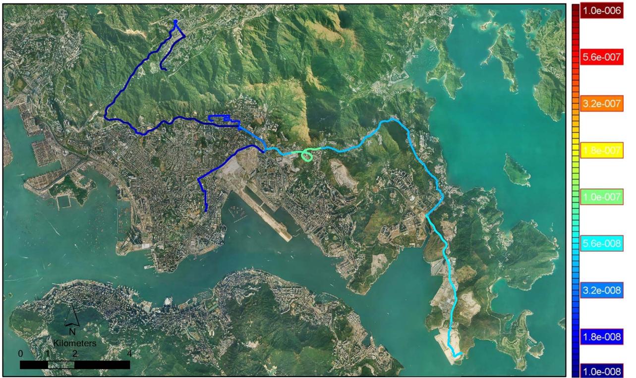
13.11.1 Individual Risk Results
The individual risk
(IR) contours associated with the Project are shown in Figure 13.5, Figure 13.6, and Figure 13.7. In Figure 13.6 and Figure 13.7, the ‘indoor’
refers to the population located inside buildings, and the ‘outdoor’ refers to
the population located outside buildings i.e. in open area. At the same
distance from a potential explosion, persons located inside buildings are more
vulnerable to explosion than persons located outside buildings as they are
exposed to more hazards such as debris from broken windows, etc. This explains
a higher individual risk for indoor population.
For the delivery
routes, the IR data represent the highest individual risk, occurring on the
road in the same lane as the explosives delivery truck. It is observed that the
maximum IR is about 8.8´10E-8 per year. This
is a low risk when compared to Hong Kong Risk Guidelines which require the
offsite IR from a fixed installation to be below 10-5 per year.
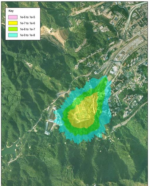
The temporary storage magazine is in a remote area. The individual risk
contours of 1 x 10⁻⁵ per year extend outside the site boundary. However this
impacts only on grassland areas where there is no continuous presence of
people. The presence of people in these
areas will be rare, with the nearest building being the Construction & Demolition material sorting facilities located about
400 m to the west of the temporary magazine site. A presence factor of 2 hours/day (about 8%) has been given to an
outside person being present in the area within 100 metres of the temporary magazine. The most exposed population group will be Mines
Delivery personnel who will be making/ receiving deliveries at the jetty. Such
persons are not expected to be present more than 8% of the time (up to 4
personnel in 2 trucks, 2 hours per day, 6 days per week) which would translate
to a presence factor of 0.08. The IR for specific individuals offsite would
therefore be about one order of magnitude less than that indicated by the IR
contours, and clearly less than 10-5 per year for all the off-site areas. Hence
it can be concluded that individual risk is acceptable.
Figure 13.5
Maximum IR for the
Delivery Routes from TKO Area 137 Magazine
Figure
13.6
IR of Proposed TKO Area 137 Magazine
Indoor Outdoor
13.11.2 Societal Risk Results
The societal risk results for explosives storage,
transport and use for SCL (TAW-HUH) have been combined to produce
the overall societal risk results for the base case and the worst case (Figure 13.7).
The Base Case
represents the risks associated with the envisaged blasting programme. It can
be seen that the risks lie in the ALARP region.
The Worst Case
represents the maximum risks associated with the worst blasting scenario. The
risks, as expected, are higher than the base case but still within the ALARP
region.
Figure 13.8 shows the F-N curve for the Base Case with a
breakdown by storage, transport and use. It is observed that risks from the
temporary magazine and use of explosive are negligible compared to the
transport risks. Indeed, the temporary magazine is located in a remote area
with very low population density nearby. The risk related to use of explosives
is also low compared to transport due to the stringent controls in place
throughout the blasting process.
The F-N curves for
both base case and worst case are within the As Low as Reasonably Practicable
(ALARP) Region as per HK EIAO-TM. Therefore, mitigation measures need to be
considered to reduce the risk. The ALARP assessment is provided in Section 9 of
Appendix 13A.
The potential Loss
of Life (PLL) for the base case and the worst case are given in Table
13.7 and Table
13.8 respectively. The
PLL for this project has been evaluated at 4.85 x 10⁻⁴ per year. The maximum PLL
value for the Project is estimated at 6.32 x 10⁻⁴ per year, which is obtained
from the worst case.
Figure
13.7 F-N
Curves for Storage, Transport and Use of Explosives
Figure 13.8
F-N
Curve for Base Case with Breakdown by Transport, Storage and
Use
Table 13.7 Potential Loss of Life for
Base Case
|
Base Case
|
PLL (per year)
|
Percentage Contribution (%)
|
|
Storage of Explosives
|
|
|
TKO Area 137
Magazine
|
9.17E-07
|
0.19%
|
|
|
|
|
|
Transport of Explosives
|
|
TKO Area 137 to
Ma Chai
Hang Ventilation
Building
|
1.80E-04
|
37.11%
|
|
TKO Area 137 to Shansi Street
Shaft
|
1.34E-04
|
27.63%
|
|
TKO Area 137 to Hin Keng Portal
|
1.62E-04
|
33.40%
|
|
|
|
|
|
Use of Explosives
|
|
|
|
Construction of
Lion Rock Tunnel (Ground shock from blast face)
|
4.73E-06
|
0.98%
|
|
Construction of
Ho Man Tin Tunnels (Ground shock from blast face)
|
6.99E-07
|
0.14%
|
|
Full load
detonation of explosives during transport to blast faces for Lion Rock Tunnel
(Blast effect)
|
3.41E-07
|
0.07%
|
|
Full load
detonation of explosives during transport to blast faces for Lion Rock Tunnel
(Ground shock)
|
8.62E-09
|
0.00%
|
|
Full load
detonation of explosives during transport to blast faces for Ho Man Tin
Tunnels (Blast effect)
|
2.12E-07
|
0.04%
|
|
Full load
detonation of explosives during transport to blast faces for Ho Man Tin
Tunnels (Ground shock)
|
1.32E-06
|
0.27%
|
|
Gas piping
rupture due to Ground shock and Blast effect (Tertiary Effect)
|
1.58E-07
|
0.03%
|
|
LPG Gas Station
Failure (Tertiary Effect)
|
1.07E-07
|
0.02%
|
|
|
|
|
|
Total
|
4.85E-04
|
100.00%
|
Table 13.8
Potential Loss of Life for Worst Case
|
Worst Case
|
PLL (per year)
|
Percentage Contribution (%)
|
|
Storage of Explosives
|
|
|
TKO Area 137
Magazine
|
9.17E-07
|
0.15%
|
|
|
|
|
|
Transport of Explosives
|
|
TKO Area 137 to
Ma Chai
Hang Ventilation
Building
|
2.32E-04
|
36.71%
|
|
TKO Area 137 to Shansi Street
Shaft
|
1.74E-04
|
27.53%
|
|
TKO Area 137 to Hin Keng Portal
|
2.16E-04
|
34.18%
|
|
|
|
|
|
Use of Explosives
|
|
|
|
Construction of
Lion Rock Tunnel (Ground shock from blast face)
|
5.68E-06
|
0.90%
|
|
Construction of
Ho Man Tin Tunnels (Ground shock from blast face)
|
8.38E-07
|
0.13%
|
|
Full load
detonation of explosives during transport to blast faces for Lion Rock Tunnel
(Blast effect)
|
4.09E-07
|
0.06%
|
|
Full load
detonation of explosives during transport to blast faces for Lion Rock Tunnel
(Ground shock)
|
1.03E-08
|
0.00%
|
|
Full load
detonation of explosives during transport to blast faces for Ho Man Tin
Tunnels (Blast effect)
|
2.54E-07
|
0.04%
|
|
Full load
detonation of explosives during transport to blast faces for Ho Man Tin
Tunnels (Ground shock)
|
1.58E-06
|
0.25%
|
|
Gas piping
rupture due to Ground shock and Blast effect (Tertiary Effect)
|
1.90E-07
|
0.03%
|
|
LPG Gas Station
Failure (Tertiary Effect)
|
1.28E-07
|
0.02%
|
|
|
|
|
|
Total
|
6.32E-04
|
100.00%
|
13.11.3 ALARP Assessment
Since the risks
posed by the project, for both cases considered, are within the ALARP region
specified in EIAO-TM Annex 4, this implies that risk reduction measures and /
or alternate options should be explored for the Project.
It was found that
the risks arising from explosives transport are much more significant than that
of explosives storage; hence the ALARP assessment focuses on the transportation
aspects of explosives.
Where the risk falls
into the ALARP region, the risks associated with each probable hazardous event
should be reduced to a level ‘as low as reasonably practicable’. This firstly
requires the identification of any ‘practicable’ options regardless of their
cost. A mitigation option is considered ‘practicable’ if an engineering
solution exists and can be implemented on the SCL (TAW-HUH) project regardless
of the cost without affecting the project construction programme. Secondly, the
extent to which the risk should be reduced is usually measured as a trade off
between the risk reduction, i.e. the safety benefits and the cost of the risk
reduction measure. A mitigation option is considered ‘reasonable’ if the cost
of implementing the option is not grossly disproportionate to the achieved
safety benefits.
Risk mitigation
measures may take the form of engineered measures, controls in the zones most
impacted by the hazardous scenarios presented by this project, or operation and
procedural controls.
Approach to
ALARP Assessment
The approach
consists of identifying potential justifiable mitigation measures, assessing their
practicability for this project and evaluating their cost and comparing with
the safety benefits of implementing the measures. Combinations of mitigation
measures are also considered.
The safety benefits
are evaluated as follows:
Safety Benefits =
Value of Preventing a Fatality x Aversion Factor x Reduction in PLL value
x Design life of mitigation measure
The Value of
Preventing a Fatality (VPF) reflects the tolerability of risk by the society
and therefore the monetary value that the society is ready to invest to prevent
a fatality. For the purpose of this assessment and for consistency with
previous studies, the Value of Preventing a Fatality is taken as HK$33M per
person, which is the same figure as used in previous Hazard Assessment studies
(derived from ref.5 but updated to current prices.
Depending on the
level of risk, the value of preventing a fatality may be adjusted to reflect
people’s aversion to high risks or scenarios with potential for multiple
fatalities. The methodology for application of the ‘aversion factor’ follows
that developed by EPD (ref.18), in which the aversion factor is calculated on a
sliding scale from 1 (risks at the lower boundary of the ALARP region of the
Risk Guidelines) up to a maximum of 20 (risks at the upper boundary of the
ALARP region). The adjusted VPF using the aversion factor of 20 is HK$660M.
This value is a measure of how much the society is willing to invest to prevent
a fatality, where there is potential for an event to cause multiple fatalities.
With reference to Appendix 13A, the maximum justifiable expenditure for this
Project is calculated as HK$ 0.62M assuming the design life of mitigation
measure is 1.5 years based on the construction phase of the SCL (TAW-HUH)
project during which storage and transport of explosives will be involved, with
the PLL of 6.23 x 10⁻⁴ per year, which is obtained from the Worst Case.
For an ‘achievable’
mitigation measure to be potentially justifiable, its cost should be less than
the Maximum Justifiable Expenditure.
Potential
Justifiable Mitigation Measures
The potential
options that have been examined in the ALARP assessment include the following
categories.
·
Options
eliminating the need for a temporary Magazine or eliminating the risk (e.g. Use
of alternative methods of construction (‘hard rock’ TBMs));
·
Options
reducing significantly the distance run by contractors’ explosive trucks such
as closer magazine sites and alternative routes. The temporary magazine and
route options considered are summarised below:
- Based
on SCL/KTE Magazine Site Selection Report (MTR 2), numerous alternative
magazine sites to TKO Area 137 for the area were considered (41 in total)
However, none of the
alternative candidate sites could either meet the Commissioner of Mines’
external separation requirements or are located farther than the proposed
magazine. Therefore, no alternative temporary magazine site option has been
considered for the ALARP assessment.
Based on a review of the possible transport routes for this project, Po Lam
Road and Anderson Road have been presented as alternative routes for explosives
deliveries from the TKO Area 137 magazine site to the Ma Chai
Hang Ventilation Building and Shansi Street Shaft and Sai
Sha Road (via Sai Kung) has
been presented as an alternative route for explosives deliveries from the TKO
Area 137 magazine site to the Hin Keng
Portal. These route options have been selected for further cost-benefit
evaluation;
·
Options
reducing significantly the quantities of explosives to be used such as use of
‘hard rock’ TBM or alternatives to cartridged emulsion.
- It is possible to use smaller explosive charges for
initiating explosives such as ‘cast boosters’. The main explosive component of
‘cast boosters’ is PETN. Using such explosives will reduce the weight of
explosives to be transported. However, PETN has a higher TNT equivalency. This
will also not eliminate the need for detonating cord. This option has been selected for
further cost benefit evaluation.
·
Options
considering improved explosive truck design; and
·
Options
considering better risk management systems and procedures.
In summary,
the following options have been considered for cost-benefit analysis.
·
Option
1: Alternative Routes - Po Lam Road, Anderson
Road and Sai Sha Road
(via Sai Kung)
·
Option
2: Use of Smaller Quantities of Explosives
The PLL for Options
1 and 2 are compared to the PLL for the appropriate Worst Case (the relevant
alternative routes for specific delivery points and the use of cast boosters
for the whole project). This was used as the basis for the cost-benefit
analysis/ ALARP assessment presented in Table 13.9.
Other options
considered practicable have been either recommended for implementation or
assessed comparing the implementation cost with the maximum justifiable
expenditure. The evaluation for each option is shown in Table 13.10. More details are available in Section 9 of Appendix 13A.
Table 13.9 Potential Loss of Life for Worst
Case, Options 1 and 2
|
Case
|
MCH/ Shansi St
|
Hin Keng
Portal
|
Overall
|
|
|
PLL per year
|
PLL per year
|
PLL per year
|
|
|
|
|
|
|
Worst Case
(Transport and Storage)
|
4.06 x 10⁻⁴
|
2.16 x 10⁻⁴
|
6.23 x 10⁻⁴
|
|
Option 1:
Alternative Routes
- Po Lam Road,
- Anderson Road,
- Sai Sha Road (via Sai Kung)
|
4.23 x 10⁻⁴
4.21 x 10⁻⁴
-
|
-
-
2.68 x 10⁻⁴
|
|
|
Option 2: Use of
Smaller Quantities of Explosives
|
-
|
-
|
3.39 x 10⁻⁴
|
Table13.10 ALARP Assessment Results
|
Option
Description
|
Practicability
|
Implementation
Cost
|
Safety
Benefits or Justifiable Expenditure
|
ALARP
Assessment
Result
|
|
Use
of alternative methods of construction (TBMs)
|
Not
Practicable
|
>
HK$ 100M
|
HK$
0.62M
|
Neither
practicable nor justified.
|
|
Use of Magazines Closer to
the Construction Sites
|
Not
Practicable
|
-
|
-
|
Closest
practicable magazine site to the construction sites has been selected
|
|
Use
of different explosive types (different types of detonating cord)
|
Pose
some limitations
|
HK$ 1M
|
No
safety benefit
|
Not
Justified
|
|
Alternative
Routes (Option Case 1)
|
Practicable
|
-
|
Negative
|
Clear Water Bay Road preferred
|
|
Use
of Smaller Explosives Quantities
(Option Case 2)
|
Practicable
|
>
HK$ 0.50M
|
HK$
0.28M
|
Use of cast boosters is not
cost effective. The cast booster option will be explored further in line with
the use of best practice in explosives selection. [1]
|
|
Safer
explosive truck (reduced fire load)
|
Practicable
|
-
|
-
|
Based
on low implementation costs, this option has been directly incorporated in
recommendations
|
|
Reduction
of Accident Involvement Frequency (training programme etc.)
|
Practicable
|
-
|
-
|
Based
on low implementation costs, this option has been directly incorporated in
recommendations
|
|
Reduction
of Fire Involvement Frequency (better emergency response, extinguisher types
etc.)
|
Practicable
|
-
|
-
|
Based
on low implementation costs, this option has been directly incorporated in
recommendations
|
Note: [1] Please
refer to Hazard to Life Assessment Final Report, Section 9.6.3, 5th paragraph of Appendix 13A.
13.11.4 Cumulative Risk Assessment
Cumulative risk assessment analyses the combined
risks of fatality arising from exposure to hazards due to storage, handling and
transport of dangerous goods in various projects being undertaken concurrently.
The projects that potentially interface with the
SCL (TAW-HUH) Project are: the Harbour Area Treatment
Scheme Stage 2A (HATS2A) project, the Kwun Tong Line Extension (KTE), Central
Kowloon Route (CKR), and the Shatin to Central Link – Cross Harbour
Section. Among the projects mentioned, the HATS2A project has been identified
as potentially overlapping with SCL (TAW-HUH) according to the project
schedules and information on geographical location for explosives activities.
HATS2A is an on-going project with the blasting period up to November 2013,
which potentially overlaps with SCL (TAW-HUH) explosives delivery schedule for
two months period on some section of explosives delivery routes. Projects other
than HATS2A are not geographically aligned with the SCL (TAW-HUH) placement
(alignment, worksites, magazine site or transport routes) or not
chronologically aligned with the blasting programme.
Therefore, cumulative risk is considered for HATS2A
project and SCL (TAW-HUH) according to the current best available blasting
information from relevant authorities and project proponent. Risk assessment
for HATS2A delivery route sections that overlaps with SCL (TAW-HUH) has been
described in Annex A of Appendix 13A.
The cumulative risk of the worst case scenario with
the consideration of a 20% increase in the number of deliveries for both
projects and conservatively an overlap period of 1 year for the explosives
delivery programme has been assessed. The resulting F-N curve remains within
the ALARP region (as shown in Figure 13.11), and the
presented conclusions would still apply. In this worst case the maximum
individual risk (IR) for the common routes has been aggregated.
As can be seen from Figures 13.9 in a worst
case scenario, the cumulative individual risk is less than 1E-05, and therefore
acceptable according to the risk criterion.
The pier in TKO Area 137 is used for the delivery
of explosives for other projects however the transport of explosives by Mines
Division is out of scope of this assessment and no cumulative risk assessment
is considered in TKO Area 137.
Figure 13.9 The
Maximum IR for the delivery route in common for the SCL (TAW-HUH) and HATS 2A
Projects

Figure 13.11 F-N
Curves showing the Cumulative Societal Risk for the common delivery routes for
the HATS2A and SCL (TAW-HUH) Projects
in the Worst Case of a 1 year overlap
As can be seen the
risk from the combined projects remains within the ALARP region. ALARP assessment
has been conducted for the SCL (TAW-HUH) project for the storage and transport
of explosives and presented in Section 9 of Appendix 13A.
13.12
PHI
Hazard Assessment for Construction and Operation Phases of the Project
13.12.1 Introduction
This Section summarises methodology and results of the Hazard Assessment
(HA) for the Shatin Water Treatment Works (STWTW) in connection with the
construction and operation of the Shatin to Central Link (SCL). The detailed HA
report is provided as Appendix 13C.
The STWTW is
designated as a Potentially Hazardous Installation (PHI). Part of the proposed
SCL railway extension and Hin Keng
Station will be located within the 1000m Consultation Zone of the Chlorine
Store of the STWTW and therefore a hazard assessment is required.
Purpose of the PHI Hazard Assessment
Section 3.4.5
of the EIA Study Brief for this project (ESB-191/2008) specifies Hazard to Life
assessments to be conducted. Part of this requirement addresses risks in
relation to Shatin WTW as follows:
The Applicant shall carry out hazard assessment to
evaluate potential hazard to life during construction and operation stages of
the Project due to Sha Tin Water Treatment Works.
The hazard assessment shall include the following:
(i) Identify hazardous
scenarios associated with the on-site transport, storage and use of chlorine at
Sha Tin Water Treatment Works and then determine a
set of relevant scenarios to be included in a Quantitative Risk Assessment
(QRA);
(ii) Execute a QRA of the set of hazardous
scenarios determined in (i), expressing population
risks in both individual and societal terms;
(iii) Compare individual and societal risks with
the criteria for evaluating hazard to life stipulated in Annex 4 of the TM; and
(iv) Identify and assess practicable and cost-effective risk
mitigation measures.
The
methodology to be used in the hazard assessment should be consistent with previous
studies having similar issues (e.g. “Reassessment of Chlorine Hazard for Eight
Existing Water Treatment Works” commissioned by Water Supplies Department).
The STWTW is
designated as a Potentially Hazardous Installation (PHI) owing to its use and storage
of chlorine in 1 tonne drums. Part of the railway
alignment and the future station at Hin Keng will be located within the 1000m Consultation Zone of
the Chlorine Store of the STWTW (Figure 13.12).
Societal risks from a PHI depend on surrounding
population levels. Consultation Zones are established around PHIs to control
developments in the vicinity and prevent population accumulating to the point
where societal risks may become unacceptable. Any new development within the
Consultation Zone of a PHI that may lead to an increase in population requires
a hazard assessment to be conducted to ensure that the societal risks remain
acceptable. The purpose of this assessment, therefore, is to assess risks from
STWTW to the surrounding population including the construction and operational
phases of SCL and Hin Keng
Station. The criteria and guidelines for assessing Hazard to Life are stated in
Annexes 4 and 22 of the Technical Memorandum (EIAO-TM Criteria).
Figure
13.12 Hin Keng
Station and SCL Alignment
13.12.2 Previous QRA study for Shatin WTW
In 1997, the Water Supplies Department (WSD)
commissioned ERM to carry out a Reassessment of Chlorine Hazards for Eight Existing
Water Treatment Works.
The approved methodology for these QRA studies is
detailed in the 8 WTW Study Methodology Report (ref. 19).
Results
for the STWTW (ref. 20) showed that:
·
The
risk was in the ‘ALARP region’; and
·
The
maximum number N of fatalities was assessed at over 900
The previous QRA study for STWTW (ERM, 2001) was
based on the following operational data:
·
223
tonnes of chlorine storage;
·
7.5
mg/l dosing giving a consumption of 3359 tonnes/year; and
·
Population
based on 1997 data, projected to year 2006.
13.12.3 Shatin WTW
Location
Shatin WTW is located at the head of a valley on Keng Hau Road, Hin
Tin to the south-west of Shatin new town. The site is approximately rectangular
in shape and measures 400m north to south by 300m east to west. The treatment
plant comprises a South Works and a North Works. The chlorination house is
located in the south-west corner of the site. The site location is shown in Figure 13.13.
Figure
13.13 Shatin
WTW and its Surrounding
Basic Operating Data
Detailed description of STWTW operations and
relevant safety features is given in Appendix 13C.
Water Supplies Department is planning a major STWTW refurbishment
programme, which is scheduled to commence in mid-2012. During the
refurbishment, since parts of the plant will have to be temporarily shut down,
the water throughput will decrease and accordingly, chlorine storage and usage
levels will be significantly reduced. Following completion of the refurbishment
at the end of 2016 water throughput will return to 1,227 Mld.
Chlorine dosage levels were assumed at 7.5 mg/l in ERM (2001) but current
dosing levels are below 2 mg/l. This will be further reduced to 1.7 mg/l
following the refurbishment, due to the introduction of new treatment
technology. This will result in a permanent reduction in chlorine usage once
refurbishment is completed in 2016. Details are presented in Table 13.11.
Table 13.11 Scenarios Considered in QRA
|
Scenario
|
Assessment year
|
Maximum Chlorine Storage at WTW (tonnes)
|
Weighted Average Chlorine Storage Time Distribution
Assumed in the QRA (tonnes, % of time)
|
Average Chlorine Usage at WTW (tonnes per year)
|
|
Scenario 1: SCL Construction (before WTW
refurbishment starts)1
|
2011
|
221
|
203
(10%)1
183
(80%)
158
(10%)
|
896
|
|
Scenario 2: Simultaneous SCL
Construction and WTW
refurbishment
|
2014
|
158
|
158
(100%)
|
642
|
|
Scenario 3: SCL Operation Period 1 (after
completion of WTW refurbishment)
|
2016
|
190
|
190
(20%)
150
(80%)
|
761
|
|
Scenario4: SCL Operation Period 2
(surrounding population growth taken into
account)
|
2031
|
190
|
190
(20%)
150
(80%)
|
761
|
|
Assumed in 2001 QRA
|
2006
|
223
|
223
(100%)
|
3359
|
Surrounding Topography
Shatin WTW is located at 30m above the Principal
Datum (PD) and is surrounded on three sides by hills rising to approximately
300m. To the north-east the land slopes gently downwards towards the town of Shatin. The topography is
of particular relevance; since chlorine is a dense gas the spread of chlorine
cloud from any large release would be restricted by the neighbouring hills and
directed towards the populated areas.
13.12.4 SCL Facilities
Of interest to this QRA is the proposed Hin Keng Station as well as the
SCL alignment and construction works areas within the Consultation Zone of
STWTW. The proposed location of the Hin Keng Station and the SCL alignment in relation to the STWTW
are shown in Figure 13.13.
The proposed Hin Keng Station construction site is located approximately
450m to the north-east of Shatin WTW chlorine store, but only some 90 m from
the WTW site entrance and its access road which is used by the trucks
delivering chlorine to the WTW. Similarly, the SCL tunnel entrance work area is
located about 375 m from the chlorine store and 150 m from the WTW access road.
13.12.5 Meteorological Conditions
For the sake of consistency, this study uses the
same meteorological data set as was used in the previous QRA (ref. 20), i.e.
the data recorded at the Shatin weather station in the year 1996 by the Hong
Kong Observatory. The weather data
have been rationalised into different combinations of wind direction, speed and
atmospheric stability class. The
probabilities of occurrence of each combination during day and night are
presented in Appendix 13C (Table 2.2).
13.12.6 Population Data
The approach to the population data used in this
study is as per the 2001 QRA for Shatin WTW (ref. 20). The population data from
the 2001 study were updated to reflect the current situation and the current
projections to the assessment years for construction and operational phases of
the project.
All the population levels were defined for a number
of GIS-based polygon, point and line population units, based on the latest
information from sources such as 2006-based by-census available from the Centamap website, Education Bureau website, 2007 Annual
Traffic Census (ref. 12), site surveys and telephone interviews etc.
SCL construction worker population and the
passenger data for MTR trains and stations are based on the information
provided by MTR.
The population data methodology and the final
population data used in this study are detailed in Appendix 13C. The total population levels are greater than
those used in the 2001 QRA (ref. 20) due to general population growth in the
area.
13.12.7 Hazard Identification
Hazard identification exercise was based on the
review of past accidents and Hazard and Operability (HAZOP) Study performed for
STWTW. Details are provided in Appendix 13C.
Various possible mechanisms for a chlorine release
identified during the HAZOP study and the review of past accidents have been
categorised in terms of the releasing inventory, hole
size and phase of release as shown in (Table 13.12). The table also screens out scenarios considered to
present negligible off-site risk.
Table 13.12
Characterisation of Chlorine Release Scenarios
|
Chlorine
release scenario
|
Outcome
|
Releasing
inventory (tonnes)
|
Hole
size (diameter)
|
Phase
|
|
1.
ACCESS ROAD
|
|
|
|
|
1.1 Truck fire
|
Considered to result in
melting of the fusible plugs on up to three drums (1):
|
3
|
3x6mm
|
liquid
|
|
1.2 Fire on the roadside
|
Considered to present
negligible off-site risk as truck does not park on site other than within chlorine
building
|
-
|
-
|
-
|
|
1.3 Manoeuvring
accident
|
Considered
to result in a single drum – small leak (eg valve
gland failure)
|
1
|
3mm
|
liquid
|
|
1.4 Rollover
|
Single drum - small
leak(e.g. valve gland failure)
Single drum - medium leak(e.g. guillotine failure of drum valve)
|
1
1
|
3mm
8mm
|
liquid
liquid
|
|
|
Three drums - medium leak
(e.g. guillotine failure of drum valves on three drums)
|
3
|
3x8mm
|
liquid
|
|
|
Fire (outcomes as item 1.1
above)
|
|
|
|
|
1.5 Collision
|
Single drum - rupture
Fire (outcomes as item 1.1 above)
|
1
|
-
|
liquid
|
|
1.6 Load- shedding
|
Single drum - small leak
|
1
|
3mm
|
liquid
|
|
|
Single drum - medium leak
|
1
|
8mm
|
liquid
|
|
1.7 Spontaneous drum failure
|
Single drum - medium leak
|
1
|
8mm
|
liquid
|
|
|
Single drum - large leak
(e.g. dislodgement of a fusible plug)
|
1
|
20mm
|
liquid
|
|
|
Single drum – rupture
|
1 (inst)
|
-
|
liquid
|
|
2. DRUM
HANDLING
|
|
|
|
|
|
|
|
|
|
2.1 Dropped drum
|
Single drum - medium leak
|
1
|
8mm
|
liquid
|
|
|
Single drum - large leak
(e.g. dislodgement of fusible plugs)
|
1
|
20mm
|
liquid
|
|
|
Single drum - rupture
|
1 (inst)
|
-
|
liquid
|
|
2.2 Collision of drum with
another object
|
Considered to present
negligible off-site risk as crane operates at low speed and drum valves are
protected by steel caps.
|
-
|
-
|
-
|
|
2.3 Accidental impact of
drum on pigtail during setdown at standby position
|
Pigtail - guillotine
failure
|
1
|
4.5mm
|
two-phase
|
|
2.4 Dropped drum due to
overextension of truck crane
|
Considered to present
negligible off-site risk as truck crane would only rarely be used
|
-
|
-
|
-
|
|
2.5 Dropped drum due
to incorrect alignment of
monorail track
|
As item 2.1 above
|
|
|
|
|
3.
CONTAINERS IN STORAGE
|
|
3.1 Leaking chlorine drums
|
Single drum - medium leak
|
1
|
8mm
|
liquid
|
|
|
Single drum - large leak
|
1
|
20mm
|
liquid
|
|
|
Single drum - rupture
|
1 (inst)
|
-
|
liquid
|
|
3.2 Overfilled drums
leading to overpressurisation on thermal expansion
|
As item 3.1 above
|
|
|
|
|
3.3 Impurities in chlorine
drum leading to explosion or leak
|
As item 3.1 above
|
|
|
|
|
3.4 Object falls onto
chlorine containers
|
Considered to present
negligible off-site risk as there are no objects likely to fall which could
cause significant damage to the drums.
|
-
|
-
|
-
|
|
3.5 Fire (external or
internal)
|
Considered to present negligible
off-site risk as chlorine stores are 2 hour fire-rated structures. The most significant internal source
of fire is considered to be the chlorine truck. However, pessimistically, all truck
fires are modelled as occurring outdoors
|
-
|
-
|
-
|
|
3.6 External explosion
|
Considered to present
negligible off-site risk as there are no significant sources of external
explosion present
|
-
|
-
|
-
|
|
3.7 Lightning strike
|
Considered to present negligible
off-site risk as the chlorine store is lightning protected and the time spent
by the truck on the access road is minimal
|
-
|
-
|
-
|
|
3.8 Extreme wind
|
Considered to present negligible
off-site risk as chlorine store is designed for typhoon loading
|
-
|
-
|
-
|
|
3.9 Flooding
|
Considered to pose
negligible risk as could only affect empty drums
|
-
|
-
|
-
|
|
3.10 Construction
activities
|
No construction activities
inside the chlorine store are anticipated during the construction and
operational phases of this project.
|
-
|
-
|
-
|
|
3.11 Subsidence
|
Considered to present
negligible off-site risk
|
-
|
-
|
-
|
|
3.12 Earthquake(2)
|
Overhead crane dislodged from
rails:
Single drum-rupture
Roof collapse:
Multiple drum-rupture
|
1 (inst)
42 (inst) (5)
|
-
|
liquid
|
|
3.13 Aircraft crash
|
Roof collapse:
Multiple drum-rupture
(similar to earthquake)
|
42 (inst)(5)
|
-
|
liquid
|
|
3.14 Sabotage
|
Considered to present
negligible off-site risk (issues of site security were considered in the
HAZOP studies and appropriate actions have been raised.)
|
-
|
-
|
-
|
|
3.15 Vehicle crash
|
Considered to present negligible
off-site risk due to robustness of chlorine store
|
-
|
-
|
-
|
|
3.16 Electromagnetic
interference
|
Considered to present
negligible off-site risk as precautions are adopted in the design of the
electrical systems.
|
-
|
-
|
-
|
|
4. CONNECTION
AND DISCONNECTION OF CHLORINE CONTAINERS
|
|
4.1 Human error or
equipment failure during connection or disconnection of drums
|
Pigtail - guillotine
failure
|
1
|
4.5mm
|
two-phase
|
|
5. CHLORINATION SYSTEM
|
|
5.1 - 5.5 Failures associated
with the chlorination system pipework
|
Liquid chlorine pipework - guillotine failure
|
1.05(3)
|
4.5mm(4)
|
two-phase
|
|
5.6 - 5.7 Failure of
evaporator
|
Evaporator - leak or
rupture
|
1.05
|
4.5mm
|
two-phase
|
Notes
(1) In the
2001 QRA a mixture of “old” and “new” chlorine drums was assumed (with 6 and 1
fusible plug, respectively). According to the recent WSD information, the “old”
drums are no longer in use, so only the “new”-type drums are considered
(2) For assessment of effects of earthquake on chlorine
store see Appendix
13C (Annex G)
(3) Inventory of drum (1 tonne) and evaporator (50kg)
(4) Diameter of liquid chlorine pipework
is 20mm but limiting orifice size is that of pigtail, i.e. 4.5mm.
(5) The
values listed are for 221 tonnes storage. For reduced storage scenarios they
are reduced in proportion to the storage levels (see discussion in Appendix
13C Annex
G).
13.12.8 Consequence Analysis
Methodology
The
assessment of the consequences of a chlorine release essentially involves three
steps:
·
modelling
the initial release of chlorine (whether inside or outside the chlorine building);
·
modelling
the dispersion of chlorine in the atmosphere;
·
assessing
the toxic impact to people off-site (whether indoors or outdoors).
In this study, the methodology for the consequence
analysis follows that of the Eight WTWs Study as detailed in the Methodology
Report (ref. 19) and the STWTW QRA (ref. 20) and is summarised below. Details
are provided in Appendix 13C.
Initial Release of
Chlorine
The
initial release of chlorine or 'source term' is modelled using standard
discharge rate formulae as detailed in ref. (19). Releases direct from the
chlorine container are the most significant and, in the case of chlorine drums,
these are modelled as liquid releases.
The rapid flashing of chlorine which occurs
following a liquid leak from a drum is conservatively assumed to result in 100%
entrainment of the liquid as aerosol with no rain-out. For catastrophic (instantaneous) liquid
releases the rapid boiling of the chlorine on contact with the ground is
assumed to result in entrainment of twice the initial flash fraction as
aerosol, following Lees (ref. 21).
The remainder of the liquid chlorine is modelled as a spreading,
evaporating pool.
For releases of chlorine within the chlorine
building, a simple 'perfect mixing' model is used to account for the initial
dilution of chlorine. Instantaneous releases of 1 tonne of chlorine are assumed
to result in pressurisation of the building to the extent that there could be a
release of chlorine via weak points in the building structure, e.g. door
seals. Continuous releases are
assumed to be entirely contained, except in the event of failure of the Contain
and Absorb system for which two modes of failure are considered: normal
ventilation remains on or a door is left open.
Dispersion of
Chlorine in the Atmosphere
Following the Eight WTWs Study, advanced techniques
are used for prediction of the dispersion of chlorine in the atmosphere. The
effects of buildings and variable ground terrain on the dispersion of chlorine
in the atmosphere are modelled. The modelling of the dispersion of chlorine in
the atmosphere involves three elements:
·
Wind
tunnel simulations;
·
Computational
Fluid Dynamics (CFD); and
·
Flat
terrain dispersion modelling.
The wind tunnel and CFD studies represent the
'state of the art' in dense gas dispersion modelling and provide the only
rigorous means of accounting for the effects of buildings and complex terrain.
Wind tunnel testing has been used to investigate a range of release conditions,
wind directions and wind speeds in near-neutral atmospheric conditions. CFD has
been used to determine the influence of atmospheric stability on the dispersion
of chlorine and provide a broad comparison against the wind tunnel results for
neutral stability. Both the wind tunnel testing and CFD modelling have included
off-site high rise buildings as well as on-site buildings as these have a
significant influence on the dispersion of the chlorine.
The role of the flat terrain
dispersion modelling has been to provide the 'source term' for both the wind
tunnel and CFD studies. The model used was DRIFT (ref. 22), an integral
dispersion model developed by AEA Technology under the sponsorship of the UK
Health and Safety Executive.
Toxic Impact
Assessment
The probit equation used to estimate the likelihood of fatality
due to exposure to chlorine is that recommended for use in QRA studies by the
Dutch Government (ref. 23); it incorporates the findings of recent
investigation into chlorine toxicity.
Table 13.13 shows the relationship between the chlorine
concentration and the probability of fatality for the TNO probit
assuming a 10 minute exposure.
Table 13.13 Chlorine
Toxicity Relationship
|
Chlorine
concentration (ppm)
|
Probit
value for 10 min exposure (TNO probit)
|
Probability
of fatality
(LD = Lethal Dose)
|
|
251
|
3.17
|
0.03 (LD03)
|
|
557
|
5.00
|
0.50 (LD50)
|
|
971
|
6.28
|
0.90 (LD90)
|
In risk
assessments for toxic gas releases it is a common practice to take into account
the possibility of escape of exposed persons. This is because at lower
concentrations of the gas, people may be able to obtain protection by moving
indoors or directly out of the cloud.
The escape modelling methodology followed in this
study is similar to that developed by the UK Health and Safety Executive (ref.
24). It assumes that a person out
of doors will have a probability of escape dependent on the chlorine cloud
concentration, with escape occurring either directly out of the cloud or to a
nearby building. The methodology
takes into account the dose received during escape as well as the subsequent
dose in the place of refuge.
Suitable conservative assumptions are made for the time of escape
bearing in mind the debilitating effect of the chlorine gas.
Incorporating all the above considerations it is
possible to calculate an ‘effective’ outdoors fatality probability, i.e. the
fatality probability that can be applied to the total outdoor population at any
given location taking into account the probability of escape.
The consequence analysis gives three fatality
probability contours for each release scenario, corresponding to 3%, 50% and
90% nominal outdoor fatality probability. The effective outdoors fatality
probabilities corresponding to these levels of fatality are shown in Table 13.14.
Table 13.14 Effective
Outdoors Probability of Fatality
|
Nominal
outdoor fatality probability
(for
a person remaining outdoors)
|
%
of population attempting escape
|
Effective
outdoor fatality probability
(taking
into account the probability of escape)
|
|
90%
|
0%
|
90%
|
|
50%
|
80%
|
31%
|
|
3%
|
80%
|
0.7%
|
Following similar previous studies undertaken in Hong Kong and elsewhere, it is assumed that the
probability of fatality for a person indoors is 10% of that for a person
remaining outdoors, i.e. nominal outdoor fatality probability.
Protection is also considered for people on the
upper floors of high rise buildings. This is based on data on the typical
height of a chlorine cloud provided by the dispersion modelling.
Certain
groups of people, i.e. the young, the elderly and the infirm will be more
sensitive to the effects of chlorine than others. This is taken into account in
the QRA by increasing the fatality rate applied to certain sensitive receivers
such as nurseries, primary schools, old people homes and hospitals.
In line with data published in ref. (25) and risk
criteria applied to sensitive developments in the UK and Australia, the
fatality rate for these groups of people is set a factor of 3.3 higher than for
the average population.
Consequence Analysis Results
Initial Release of
Chlorine
The results of the 'source term' modelling of
chlorine releases are summarised in Appendix 13C (Table 4.3).It
is apparent from that table that releases from a drum due to melting of the
fusible plugs or dislodgement of the plugs occur sufficiently rapidly to cause
emptying of the drum in a short period of time (within a few minutes).
Therefore these release cases are treated as effectively instantaneous
releases.
It is also apparent that the chlorine building has
a significant effect in modifying the release of chlorine to the atmosphere,
given failure of the Contain and Absorb system. The rate of chlorine release is
reduced dramatically (e.g. for a medium leak the rate of chlorine to atmosphere
is reduced from 1.4 kg/s to 0.3 kg/s or 0.13 kg/s) and the chlorine becomes
diluted in the building air. The failure mode of the Contain and Absorb system
'Normal ventilation remains on' is a more
severe case than 'Door left open' in terms of the chlorine release rate to
atmosphere. This is because the normal ventilation (typically 2.6 air changes
per hour) provides a more rapid release of chlorine to the environment than if
a door is left open (normal ventilation shutdown, chlorine scrubber system in
operation).
Chlorine Dispersion Modelling Results
The results of wind tunnel testing for Shatin WTW are presented in Appendix 13C (Table 4.4
and Annex B). The key findings of the wind tunnel testing may be summarised as
follows:
·
the
wind tunnel results show that the LD03 contour only exceeds the site boundary
for 1 tonne instantaneous releases.
For 1.4 kg/s and 0.5 kg/s continuous releases the LD03 does not extend
off-site; and
·
the LD
contours for the 1 tonne instantaneous release cases are strongly influenced by
the topography and buildings near Shatin WTW. In particular:
- the chlorine clouds are constrained by the hills
surrounding the WTW on three sides.
However it is noted that the LD03 contour does extend to an elevation of
100m above Principal Datum (NNE wind direction) with significant concentrations
of chlorine also present at greater elevations (e.g. 30 ppm at 200m above PD);
and
- the nearest high rise blocks of the Hin Keng Estate
act as an effective barrier to chlorine dispersion in the WSW direction with
the chlorine cloud instead diverting down the Shatin valley (i.e. following the
path of least resistance).
The results of the CFD modelling for Shatin WTW and
Tai Po Tau WTW are presented in Appendix 13C (Table 4.5
and Annex C). The key findings may
be summarised as follows:
·
Atmospheric
stability does not significantly influence the hazard range of either a 1.4
kg/s continuous release of chlorine or a 1 tonne instantaneous release of
chlorine for the two weather conditions of most interest in this study (i.e. D
- neutral stability and F - stable conditions). This is because, in the presence of
buildings and complex, heavily-vegetated terrain, atmospheric stability has
less of an influence on chlorine dispersion;
·
For B
(unstable conditions) the CFD results for Tai Po Tau WTW indicate that the
chlorine hazard range is significantly reduced compared to neutral conditions
(i.e. a factor of 2.5 shorter for a 1 tonne instantaneous release). HSL indicate that this is due to the
unstable wind field which significantly enhances vertical dispersion of the
chlorine. However, as B conditions
account for no more than 20% of the weather in Hong Kong, this is not
considered a significant factor for the QRA (i.e. risks are not considered to
be significantly overestimated by ignoring B conditions); and
·
For F
(stable conditions) the CFD results for Tai Po Tau WTW indicate that, whilst
the chlorine hazard range is not significantly affected by atmospheric
stability, the direction of travel of the chlorine cloud may be affected. At Tai Po Tau WTW, the chlorine releases
in F conditions more closely followed the topographic contours than the
equivalent releases in D conditions, which followed the direction of the wind.
The results of the flat terrain dispersion
modelling using DRIFT are presented in Appendix 13C (Table 4.6
and Annex A). From the modelling results it is possible to derive a
relationship between the chlorine release rate (or release quantity) and the
downwind hazard range. The relationship is used in the QRA, as described below.
Table 13.15 compares the key results from the wind tunnel
testing, CFD modelling, and DRIFT flat terrain dispersion modelling.
Table 13.15
Comparison of Wind Tunnel, CFD and DRIFT Results (Neutral stability, 2m/s wind
speed)
|
Release case
|
Maximum
extent of LD03 contour (m)
|
|
|
Wind tunnel
|
CFD
|
DRIFT
|
|
0.2
kg/s continuous
|
<125
|
-
|
182
|
|
1.4
kg/s continuous
|
<125
|
260
|
550
|
|
1
tonne instantaneous
|
250-650
|
255
|
600
|
From Table 13.15 the following key points emerge:
·
the
chlorine hazard range predicted by the wind tunnel testing and CFD modelling is
generally shorter than that predicted by the DRIFT flat terrain dispersion
modelling, particularly for continuous-type releases. This highlights the importance of
modelling the effects of buildings and complex terrain, which act to increase
turbulence and cause greater mixing of the chlorine. (It should also be noted that
there is an inherent limitation in models such as DRIFT, whereby the surface
roughness chosen must be small in relation to the cloud height. For dense gas release this limits the
scope of DRIFT-type simulations to relatively smooth terrain, which is not
applicable to Hong Kong conditions);
·
the
hazard range predicted by the wind tunnel testing for the 1.4 kg/s continuous
release case is significantly shorter than that predicted by the CFD modelling
(less than half). The reason for
this is not certain, however an independent technical review of the wind tunnel
testing highlighted the limitation of modelling this type of release in the
wind tunnel (1:500 scale) due to the difficulty of accurately simulating
turbulence close to the ground near the source of the release. It is possible, therefore, that in the
wind tunnel the degree of turbulence was greater than would occur in practice
for this type of release. In view
of this, the QRA uses the CFD modelling results for this release, in preference
to those generated by the wind tunnel; and
·
the
hazard range predicted by the wind tunnel for 1 tonne instantaneous releases
are greater than those predicted by the CFD modelling. The reason for this is not clear,
however as the wind tunnel results err on the conservative side (whilst eliminating
the pessimism in the DRIFT-type predictions for these releases) they have been
used in preference in the QRA.
Rationalisation of Chlorine Dispersion
Modelling Results
The preceding sections have discussed the results
arising from the various strands of work on chlorine dispersion modelling. The following paragraphs summarise how
these results have been applied in the QRA. More details are provided in Appendix 13C (Annex D).
Wind tunnel testing: the wind direction-specific cloud shapes
generated in the wind tunnel have been used directly in the QRA. This has been
achieved through use of Graphical Information Systems (GIS) software which is
described in further detail below.
Another output of the wind tunnel testing was the influence of wind
speed on the chlorine hazard range.
From the wind tunnel test results for all eight WTWs a simple scale
factor was derived to modify the cloud contours for the 2m/s wind speed case to
determine those for the 5m/s case.
CFD modelling: the
CFD modelling results show no significant influence of atmospheric stability on
the chlorine hazard range (for D and F conditions), therefore this parameter is
not considered further in the QRA.
However the CFD results for the 1.4 kg/s continuous release case (D2
weather conditions), which are consistent for Shatin WTW and Tai Po Tau WTW,
are used in the QRA in preference to those from the wind tunnel.
DRIFT modelling: the
DRIFT flat terrain dispersion modelling results are not used directly in the
QRA. However the relationships
derived from the DRIFT modelling for the chlorine release rate/quantity versus
hazard range are used to scale the wind tunnel results for the complete range
of release scenarios which need to be considered in the
QRA.
Chlorine Cloud
Height
Information on the height of a chlorine cloud has
been obtained from the wind tunnel simulations, CFD modelling and DRIFT flat
terrain dispersion modelling. This is useful for determining the degree of
protection of people inside high rise buildings. Details are provided in Appendix 13C.
13.12.9 Rationalisation of Chlorine Release
Scenarios and Estimation of Scenario Frequencies
Rationalisation of
Chlorine Release Scenarios
The
consequence analysis from wind tunnel testing and CFD modelling shows that it
is only certain, severe types of chlorine release which could produce fatal
off-site concentrations of chlorine. The release cases which fall into this category
are external continuous releases of 1.4 kg/s or more (equivalent to guillotine
failure of a drum valve) and instantaneous releases of 1 tonne or more whether
external or internal.
These results mean that many of the chlorine
release scenarios identified in Table 13.12 can be eliminated from further consideration in
the QRA. Details are provided in Appendix 13C. The results of this ‘rationalisation’ process are
shown in Table
13.16 which groups the release scenarios into 'events' having identical
release characteristics (i.e. the same release rate, duration and phase of
release).
Table 13.16 Release
Scenarios Included in QRA
|
Event
Ref
|
Component
scenarios
|
Release
rate (or quantity) to atmosphere
|
Type
of release
|
Release
location
|
|
RU1TSML
|
Rollover
Loadshedding
Spontaneous leak
|
1.4 kg/s
|
Continuous
|
Access road
|
|
RU1TMML
|
Rollover
Truck fire
|
4.2 kg/s
|
Continuous
|
Access road
|
|
RU1TSRU
|
Truck impact
Truck fire
Spontaneous failure
|
1 tonne
|
Instantaneous
|
Access road
|
|
EU1TMRU
|
Earthquake: roof collapse,
ground acceleration 0.7g
|
26.8(1) tonnes
|
Instantaneous
|
Chlorine store
|
|
EU1TMRU1G
|
Earthquake: roof collapse,
ground acceleration 1g
|
26.8(1) tonnes
|
Instantaneous
|
Chlorine store
|
|
AU1TMRU
|
Aircraft crash
|
26.8(1) tonnes
|
Instantaneous
|
Chlorine store
|
Note (1): the values listed are for 221 tonnes
storage. For reduced storage scenarios they are reduced in proportion to the
storage levels. For large instantaneous releases, such as the rupture of 42
drums in an earthquake, only 64% of the chlorine is estimated to be released
instantaneously to atmosphere as vapour and entrained aerosol. This comprises the initial vapour flash
fraction (19%) plus the entrained aerosol (2 x 19%) plus the contribution from
the evaporating chlorine pool over the first minute (7%).
Frequency Estimation
Having
identified the chlorine release scenarios of interest, the next step in the
Hazard Assessment is to determine their frequency of occurrence. This is based on the approach adopted in
ref. (20).
The base frequency data used in the frequency
calculations are shown in Appendix 13C (Table 5.4).
Actual frequencies are determined from these base failure data and the
operational parameters of the WTW such as chlorine use, chlorine storage
levels, length of the access road etc. The resulting total event frequencies
are presented in Table 13.17.
Table 13.17 Event
Frequencies
|
Event
Ref
|
Component
scenarios
|
Frequencies
(per
year)
|
Time
periods during which event could occur
|
|
RU1TSML1
|
Rollover
Loadshedding
Spontaneous leak
|
3.21E-6
7.79E-7
2.54E-7
|
All except Night
All except Night
All except Night
|
|
|
Total
|
4.24E-6
|
|
|
RU1TMML1
|
Rollover
Truck fire
|
2.35E-7
4.52E-7
|
All except Night
All except Night
|
|
|
Total
|
6.87E-7
|
|
|
RU1TSRU1
|
Truck impact
Spontaneous drum failure
Total
|
7.66E-7
1.25E-7
8.91E-7
|
All except Night
All except Night
|
|
EU1TMRU
|
Earthquake
|
4.0E-8
|
All
|
|
EU1TMRU1G
|
Earthquake
|
1.25E-8
|
All
|
|
AU1TMRU
|
Aircraft crash
|
1.44E-9
|
All
|
Note 1: Frequencies for the access road events are proportional to the
number of chlorine trucks per year and are shown here for the WTW chlorine
usage of 896 tonnes (150 trucks) per year. Frequencies for other scenarios were
reduced according to the annual number of trucks and the length of the access
route assumed.
13.12.10 Quantitative Risk Assessment
Risk Assessment Methodology
The QRA combines information on the consequences of
chlorine releases with information on the likelihood of releases to generate
two measures of risk -individual risk and societal risk. Individual risk is the chance of death
per year to a specified individual at a specific location. Societal risk is the risk to the
population as a whole.
The QRA has been undertaken using a GIS-based
software GISRisk, developed for the 8WTW
project. The GIS component of the
software enables the complex cloud shapes generated by the wind tunnel to be
input directly into the QRA. It
also provides a graphical interface by which the population data, chlorine
cloud (LD) contours and individual risk contours can be viewed on a base map of
the area. GISRisk
is an application of standard, well-validated, commercial software, i.e. ESRI's
ARCVIEW GIS software, Microsoft Access and Microsoft Excel. The main outputs
from the software are as follows:
·
Individual
risk in the form iso-risk contours overlaid on a base map of the area;
·
Societal
risk in the form of an FN curve, which is a graphical representation of the
cumulative frequency (F) of N or more fatalities plotted against N on a log-log
scale; and
·
Societal
risk in the form of a Potential Loss of Life (PLL) value, which expresses the
risk to the population as a whole and for each scenario and its location. The PLL is an integrated measure of
societal risk obtained by summing the product of each f-N pair, as below:
PLL
= f1N1+f2N2+…
+ fnNn
Risk Criteria
The Hong Kong Planning Standards and Guidelines
(HKPSG), Chapter 12 require that development proposals within the Consultation
Zone of a Potentially Hazardous Installation (PHI) should be assessed against
Government Risk Guidelines (HKRG) to ensure that risks to the public are
confined to within acceptable limits.
Acceptable risk levels are defined as follows:
·
Individual
Risk: The maximum involuntary individual risk of death associated with
accidents arising at PHIs should not exceed 1 chance in 100,000 per year
(10-5/yr); and
·
Societal
Risk: The societal risk associated with a PHI should comply with the FN diagram
(Figure
13.1). Three areas of risk are
shown:
Acceptable where risks are so low that no action is
necessary;
Unacceptable where risks are so high that they should usually
be reduced regardless of the cost or else the hazardous activity should not
proceed; and
ALARP (As Low As
Reasonably Practicable) where the risks
associated with each probable hazardous event at the PHI should be reduced to a
level as low as reasonably practicable, usually measured as a trade off between
the risk reduction afforded and the cost of that reduction. Risk mitigation
measures may take the form of either engineered measures at the PHI or development
(i.e. population) controls in the vicinity of the PHI. In the case of a new
development within the Consultation Zone of an existing PHI the onus is on the
developer to implement such measures as are necessary to ensure that risk
levels at the development site are ALARP.
Scenarios Considered for
Base Case Assessment
Four scenarios have been considered
in the QRA including two stages of the construction phase and the two periods
of the SCL operation. The main assumptions of these scenarios, based on the WTW
operational data and supplementary information from WSD are listed in Table 13.11. The chlorine storage levels and their time distribution for the future scenarios have been
agreed with WSD.
Results of the QRA
The FN curves for each scenario listed in Table 13.11 are presented in Figure 13.14 to Figure 13.17. Table 13.19
summarises the maximum N numbers derived from these figures. PLL results are
discussed in detail in Appendix 13C.
Scenario 1 (SCL
Construction before WTW refurbishment)
FN curve for the 2011 construction Phase Scenario is
shown in Figure 13.14. The risks to
total population within consultation zone and SCL construction population are
in the “ALARP” zone of HKRG. The risk to SCL construction population, when
considered on its own, falls within the “acceptable” region.
Scenario 2
(Simultaneous SCL Construction Phase and WTW Refurbishment)
For the 2014 construction phase (Figure 13.15), during the WTW refurbishment
period FN curve is again in the “ALARP” region, even that the additional
population of the refurbishment workers, located very close to the potential
chlorine release locations is taken into account.
The risk to SCL construction population, when
considered on its own, falls within the “acceptable” region.
Scenarios 3 and 4
(Operational Phase Periods 1 and 2)
The Societal Risk results for the Operational Phase fall in the “ALARP”
region of the HKRG (Figures 13.16 and 13.17). The risks to the SCL population alone (considering HIK Station and the
train populations) lie within “acceptable” region.
Figure
13.14 FN Curves: Scenario 1 (SCL Construction before WTW Refurbishment)
Figure 13.15 FN Curves: Scenario 2 (Simultaneous
SCL Construction and WTW Refurbishment)
Figure
13.16 FN Curves: Scenario 3 (Operational Phase 2016)
Figure
13.17 FN Curves: Scenario 4 (Operational Phase 2031)
Table 13.18 Maximum
N Value within the FN Chart for the Scenarios considered in QRA
|
Scenario
|
Assessment
year
|
Max
N for
F
> 1 x 10⁻⁹
|
|
Scenario
1: SCL Construction before WTW refurbishment 1
|
2011
|
990
|
|
Scenario
2: Simultaneous SCL Construction and WTW refurbishment
|
2014
|
864
|
|
Scenario
3: SCL Operation Period 1 (after completion of WTW refurbishment)
|
2016
|
900
|
|
Scenario4:
SCL Operation Period 2 (surrounding population growth taken into account)
|
2031
|
900
|
|
2001
QRA (ref. 20)
|
2006
|
980
|
Societal Risk Result Analysis and Discussion
The high number of fatalities shown in the figures
above and Table
13.18 are due to the low frequency/high fatality events such as a multiple
drum failures which can result from the chlorine store roof collapse during a
significant (ground acceleration greater than 0.7g) earthquake.
While the earthquake scenarios are dominant for the
high N values of the FN curve, the chlorine truck accident scenarios that can
affect only the populations close to WTW and on their own contribute to about
560 fatalities have higher frequencies than earthquakes, and contribute about
50% to 80% to the total PLL.
For more discussion of the societal risk results
see Section 6.3.2 of Appendix 13C.
Individual Risk
The individual risk levels are calculated for a hypothetical
person spending 100% of their time outdoors in the vicinity of the Shatin
WTW.
Figure 13.18 presents the individual risks obtained for the
Scenario 1, but assuming the maximum chlorine storage of 221 tonnes and 896
tonnes usage. Risks for other scenarios will be slightly lower due to the lower
average chlorine storage and dosage levels (Table 13.11). As can be seen, the risks are low and nowhere outside
the WTW site boundary does the individual risk exceed 10-5 per year. It is
therefore concluded that Shatin WTW complies with the individual risk criteria.
Figure 13.18 Individual Risk Contours
Results Summary
The 2001 STWTW QRA predicted the societal risk
within the “ALARP” region of the HKRG, but very close to the 1000 fatality
criterion. Any increase in
population due to natural growth or any new development including transient
construction workforce might therefore be expected to result in exceedance of
the HKRG criteria (ie N>1000).
Nevertheless, societal risk levels for all
scenarios studied are within the ALARP region (N<1000). This is due to the
lower chlorine storage and use anticipated during and after the WTW
refurbishment. For the SCL construction period before the WTW refurbishment
begins, WSD has agreed to maintain the chlorine storage time distribution (see
the first row of Table 13.11) that will not lead to an exceedance of the
N<1000 criterion.
In terms of the Potential Loss of Life, the SCL
construction contributes about 42%, and 19% of the total PLL value for the 2011
and 2014 scenarios, respectively, while for both operational phase scenarios (2016
and 2031) the PLL for the SCL passengers and HIK Station population amounts to
about 33% of the total PLL. Of the background population units, the highest
contribution to PLL results from Hin Keng Estate and road
population of Che Kung Miu
Road, and, during the WTW refurbishment, from the refurbishment workforce
The individual risk levels are low and in
compliance with HKRG.
13.12.11 ALARP Assessment
Since the societal risk levels for all scenarios
considered lie in the ALARP zone of the HKRG, mitigation measures are required
to reduce the risks to levels As Low As Reasonably Practicable. In order to
select and justify the most suitable risk mitigation, a detailed analysis has
been carried out (Appendix 13C, Section 7) concluding that none of the proposed
mitigating options could be deemed practicable based on the cost-benefit
analysis.
Nevertheless, the following measures reducing the risks
to the SCL staff, construction workers and passengers are recommended for
implementation as a matter of good practice:
·
Installation
of on-site gas monitors in all relevant SCL construction/operation areas;
·
Establishment
of emergency response and evacuation plans (co-operation of various
parties/departments required. For the operational phase the emergency plan
should also include adequate procedures for controlling the tunnel ventilation
system and stopping of the SCL train traffic in order to prevent the trains
moving into the affected areas.); and
·
Safety/emergency
response/evacuation training and drills for all personnel
A QRA has been
carried out to assess the hazard to life issues arising from the storage,
transport and use of explosives during construction of the SCL (TAW-HUH)
Project.
The criterion of
Annex 4 of the EIAO-TM for Individual Risk is met with regards to the hazards
to life posed by transport, storage and use of explosives. The assessment
results show that the societal risk for the storage and use of explosives lies
within the acceptable region, and the transport of explosives lies within the
ALARP region when compared to the criteria stipulated in the EIAO-TM. A
detailed ALARP assessment has been undertaken considering a wide range of
mitigation measures and the results show compliance with the ALARP principles
provided that the following recommendations are followed.
The criterion of
Annex 4 of the EIAO-TM for Societal Risk is also met with regards to the
hazards to life posed by the Shatin Water Treatment Works during both
construction and operational phases of the project. The assessment results show
that the societal risk lies within the ALARP region of the HKRG. An ALARP
assessment has been carried out by identifying all practicable mitigation
measures and the results show compliance with the ALARP principles provided
that the following recommendations are followed.
Following the ALARP principles, the following
recommendations are justified and should be implemented to meet the EIAO-TM
requirements:
·
The
truck design should comply with the Requirements for Approval of an Explosives
Delivery Vehicle (CEDD 2) and limit the amount of combustibles in the cabin.
The fuel carried in the fuel tank should also be minimised to reduce the
duration of any fire;
·
The
explosive truck accident frequency should be minimized by implementing a
dedicated training programme for both the driver and his attendants, including
regular briefing sessions, implementation of a defensive driving attitude. In
addition, drivers should be selected based on good safety record, and medical
checks;
·
The
contractor should as far as practicable combine the explosive deliveries for a
given work area;
·
Only
the required quantity of explosives for a particular blast should be
transported to avoid the return of unused explosives to the magazines.
·
Whenever
practicable, a minimum headway between two consecutive truck convoys of 10 min
is recommended; and
·
The
explosive truck fire involvement frequency should be minimised by ensuring the
implementation of a robust emergency response and training to make sure the
adequate fire extinguishers are used and attempt is made to evacuate the area
of the incident or securing the explosive load if possible. All explosive
vehicles should be equipped the required amount and type of fire extinguishers
and shall be agreed with Mines Division;
·
The
Contractor should as far as practicable use the preferred transport route; and
·
The
Contractor should coordinate explosives deliveries with the delivery of
chlorine to Shatin Water Treatment Works in order to avoid overlapping.
General Recommendations
Blasting activities
including storage and transport of explosives should be supervised and audited
by competent site staff to ensure strict compliance with the blasting permit
conditions. The following general recommendation should also be considered for
the storage and transport of explosives:
·
The
security plan should address different alert security level to reduce opportunity
for arson / deliberate initiation of explosives. The corresponding security
procedure should be implemented with respect to prevailing security alert
status announced by the Government.
·
Emergency
plan (i.e. magazine operational manual) shall be developed to address
uncontrolled fire in magazine area and transport. The case of fire near an
explosive carrying truck in jammed traffic should also be covered. Drill of the
emergency plan should be carried out at regular intervals.
·
Adverse
weather working guideline should be developed to clearly define procedure for
transport explosives during thunderstorm.
·
The
magazine storage quantities need to be reported on a monthly basis to ensure
that the two day storage capacity is not exceeded.
Storage of Explosives in Magazine Store
The magazine should
be designed, operated and maintained in accordance with Mines Division
guidelines and appropriate industry best practice. In addition, the following
recommendations should be implemented:
·
A
suitable work control system should be introduced, such as an operational
manual including Permit-to-Work system, to ensure that work activities
undertaken during the operation of the magazine are properly controlled.
·
There
should be good house-keeping within the magazine to ensure that combustible
materials are not allowed to accumulate.
·
The
magazine shall be without open drains, traps, pits or pockets into which any
molten ammonium nitrate could flow and be confined in the event of a fire.
·
The
magazine building shall be regularly checked for water seepage through the
roof, walls or floor.
·
Caked
explosives shall be disposed of in an appropriate manner.
·
Delivery
vehicles shall not be permitted to remain within the secured fenced off
magazine store area.
·
Good
housekeeping outside the magazine stores to be followed to ensure combustibles
(including vegetation) are removed.
·
A speed
limit within the magazine area should be enforced to reduce the risk of a
vehicle impact or incident within the magazine area.
·
Traffic
Management should be implemented within the magazine site, to ensure that no
more than 1 vehicle will be loaded at any time, in order to avoid accidents
involving multiple vehicles within the site boundary. Based on the construction
programme, considering that 6 trucks could be loaded over a peak 2 hour period,
this is considered feasible.
·
The
design of the fill slope close to the magazine site should consider potential
washout failures and incorporate engineering measures to prevent a washout
causing damage to the magazine stores.
Transport of Explosives
General Recommendations:
The following
measures should be considered for safe transport of explosives:
·
Detonators
shall not be transported in the same vehicle with other Class 1 explosives.
Separation of vehicles should be maintained during the whole trip.
·
Location
for stopping and unloading from truck to be provided as close as possible to
shaft, free from dropped loads, hot work, etc. during time of unloading.
·
Develop
procedure to ensure that parking space on the site is available for the
explosive truck. Confirmation of parking space should be communicated to truck
drivers before delivery. If parking space on site cannot be secure, delivery
should not commence.
·
During
transport of the explosives within the tunnel, hot work or other activities
should not be permitted in the vicinity of the explosives offloading or
charging activities.
·
Ensure
lining is provided within the transportation box on the vehicle and in good
condition before transportation.
·
Ensure
that packaging of detonators remains intact until handed over at blasting site.
·
Emergency
plan to include activation of fuel and battery isolation switches on vehicle
when fire breaks out to prevent fire spreading and reducing likelihood of
prolonged fire leading to explosion.
·
Use
only experienced driver(s) with good safety record.
·
Ensure
that cartridged emulsion packages are damage free before every trip.
Contractors Licensed Vehicle Recommended
Safety Requirements:
·
Battery
isolation switch;
·
Front mounted
exhaust with spark arrestor;
·
Fuel
level should be kept as far as possible to the minimum level required for the
transport of explosives;
·
Minimum
1 x 9 kg water based AFFF fire extinguisher to be provided;
·
Minimum
1 x 9 kg dry chemical powder fire extinguisher to be provided;
·
Horizontal
fire screen on cargo deck and vertical fire screen mounted at least 150mm
behind the drivers cab and 100mm from the steel cargo compartment, the vertical
screen shall protrude 150mm in excess of all three ( 3 ) sides of the steel
cargo compartment;
·
Cigarette
lighter removed;
·
Two ( 2
) battery powered torches for night deliveries;
·
Vehicles
shall be brand new, dedicated explosive transport vehicles and should be
maintained in good operating condition;
·
Daily
checks on tyres and vehicle integrity;
·
Regular
monthly vehicle inspections;
- Fuel system
- Exhaust system
- Brakes
- Electrics
- Battery
- Cooling system
- Engine oil leaks
·
Vehicle
log book in which monthly inspections and maintenance requirements are
recorded; and
·
Mobile
telephone equipped.
Recommended
Requirements for the Driver of the Explosive Vehicles:
The driver shall:
·
be
registered by the Commissioner of Mines and must be over the age of 25 years
with proven accident free records and more than 7 year driving experience without
suspension.
·
hold a
Driving License for the class of vehicle for at least one ( 1 ) year;
·
adopt a
safe driving practice including having attended a defensive driving course;
·
pass a
medical check and is assessed as fit to drive explosives vehicles;
·
not be
dependent on banned substances;
Some of the following requirements may also apply to the vehicle
attendant(s).
·
The
driver is required to attend relevant training courses recognized by the
Commissioner of Mines. The training courses should include the following major
subjects, but not limited to:
- the laws and Regulations relating to the transport
of explosives;
- security and safe handling during the transport of
explosives;
·
Attend
training courses provided by the explosives manufacturer or distributor,
covering the following:
- explosives identification;
- explosion hazards; and
- explosives sensitivity;
- the dangers which could be caused by the types of
explosives;
- the packaging, labelling and characteristics of the
types of explosives;
- the use of fire extinguishers and fire fighting
procedures; and
- emergency response procedures in case of accidents.
The driver should additionally be responsible for the following:
·
The
driver shall have a full set of Material Safety Data Sheets ( MSDS ) for each
individual explosive aboard the vehicle for the particular journey;
·
The
MSDS and Removal Permit ( where applicable ) shall be produced to any officer
of the Mines Division of CEDD upon request;
·
A card
detailing emergency procedures shall be kept on board and displayed in a
prominent place on the drivers door;
·
Before
leaving the magazine the driver together with and/or assisted by the shotfirer
shall check the following:
·
Packaging
integrity and labelling;
·
Check
that the types and quantities of explosives loaded onto the vehicle are as
stipulated in the Removal Permit(s);
·
Check
that the explosive load does not exceed the quantities stated in the removal
permit;
·
Check
the condition and integrity of the cargo compartment or box;
·
Check
that detonators are not loaded in the explosives cargo compartment and vice
versa;
·
Check
that the cargo is secured and cannot be damaged during the delivery;
·
Ensure
that the appropriate placards and a red flag are displayed before leaving the
magazine;
·
Be
competent to operate all equipment onboard the vehicle including fire
extinguishers and the vehicle emergency cut-off switches;
·
Prohibit
smoking when the vehicle is loaded with explosives;
·
When
explosives are loaded, ensure the vehicle is not left unattended;
·
Be
conversant with emergency response procedures.
Specific Recommended
Requirements for the Explosive Vehicle Attendants:
When the vehicle is
loaded with explosives, it shall be attended by the driver and at least one (1)
other person authorized by the Commissioner of Mines. The vehicle attendant
shall:
·
Be the
assistant to the driver in normal working conditions and in case of any
emergency
·
Be
conversant with the emergency response procedures
·
Be
competent to use the fire extinguishers and the vehicle emergency cut-off
switches
·
One of
the vehicle attendant(s) should be equipped with mobile phones and the relevant
MSDS and emergency response plan.
Type of Explosives &
their Disposal
For explosive selection, the following should be considered
·
Cartridged
Emulsions with perchlorate formulation should be avoided;
·
Cartridged
Emulsions with high water content should be preferred.
If disposal is required for small quantities, disposal should be made in
a controlled and safe manner by a Registered Shotfirer.
Use of Explosives
The following recommendations should be considered for the safe use of
explosives.
·
Blast
charge weight (MIC) should be within the maximum MIC as specified for the given
section.
·
Temporary
mitigation measures such as blast doors or heavy duty blast curtains should be
installed at the access adits, shafts/ portals and at suitable locations
underground to prevent flyrock and control the air overpressure.
·
Blasting
from multiple faces as well as different locations will be carried out for this
project. Good communication and control will need to be adopted in ensuring
that the works are carried out safely.
·
It is
intended that complete evacuation of the underground tunnels need not be
carried out and secure refuge areas should be identified to workers in the
area.
·
A Chief
Shotfirer and a Blasting Engineer shall be employed in addition to the normal
blasting personnel to ensure that the works are coordinated between blasting
areas and between adjacent contracts.
·
Shotfirer
to be provided with a lightning detector, and appropriate control measures
should be in place.
·
A speed
limit for the diesel vehicle truck and bulk emulsion truck in the tunnel should
be enforced. The truck may be escorted while underground to ensure route is
clear from hazards and obstructions.
·
Hot
work should be suspended during passage of the diesel vehicle truck and bulk
emulsion truck in the tunnel.
·
For any
construction works related to use of explosives near gas facilities and gas
pipes, the requirements of the Code of Practice on Avoiding Danger from Gas
Pipes must be respected, in particular, to ensure liaison/coordination with
HKCG with sufficient notice of planned works and to follow prescribed emergency
procedures in case of leaks.
·
A
detailed liaison between the contractor and HKCG should be established. HKCG
should be notified about the blasting schedule in written format within a
reasonable period of time prior to blasting in order to ensure the gas safety
during the construction period. Also, liaison should be made with HKCG to
develop an emergency plan.
Shatin Water Treatment Works PHI
The following
measures reducing the risks to the SCL staff, construction workers and
passengers are recommended for implementation as a matter of good practice:
·
Installation
of on-site gas monitors in all relevant SCL construction/operation areas;
·
Establishment
of emergency response and evacuation plans (co-operation of various
parties/departments required. For the operational phase the emergency plan
should also include adequate procedures for controlling the tunnel ventilation
system and stopping of the SCL train traffic in order to prevent the trains
moving into the affected areas.); and
·
Safety/emergency
response/evacuation training and drills for all personnel
1. MTR,
Consultancy Agreement No. NEX/2201, SCL Tai Wai to Hung Hom Section Preliminary Design Draft Final Report (MTR 1)
2. ERM, West Island Line: Hazard to Life Assessment for the
Transport Storage and Use of Explosives, 2008 (EIA153/2008) (ERM, 2008)
3. HSC,
Selection and Use of Explosion Effects and Consequence Models for Explosives,
Advisory Committee on Dangerous Substances, 2000 (ESTC, 2000)
4. DNV, The
Risk Assessment of the Transport of Explosives in Hong Kong QRA Report,
Environmental Protection Department Hong Kong Government, 1997, EPD CE63/94
(DNV, 1997)
5. ACDS,
Risk from Handling Explosives in Ports, HSC Advisory Committee on Dangerous
Substances, HMSO, UK, 1995 (ACDS, 1995)
6. P A Moreton, An
Investigation of the Relative Risks from the Road Transport of Blasting
Explosives in Maximum Size Loads of 5te and 16te, February 1993, SRD/HSE R596 (Moreton, 1993)
7. United
Nations, Recommendations on the Transport of Dangerous Goods – Manual of Tests
and Criteria, 5th Revised Edition, 2009 (TDG-Test Manual, 2009)
8. United
Nations, Recommendations on the Transport of Dangerous Goods – Model
Regulations, 16th Revised Edition, 2009 (TDG-Model Regulation, 2009)
9.
CEDD, Guidance Note on
Requirements for Approval of an Explosives Delivery Vehicle, http://www.cedd.gov.hk/eng/services/mines_quarries/doc/gn_03_edv.pdf (CEDD 2)
10.
CEDD, How to apply for a
Mode A Explosives Store Licence, http://www.cedd.gov.hk/eng/services/mines_quarries/doc/mode_a_store.pdf (CEDD 3)
11. Lands
Department, Geographic Information System (GIS) database, http://www.landsd.gov.hk/mapping/en/digital_map/mapprod.htm The
latest information on the GIS map of buildings from the Lands Department used
in this study comes from 2007/2008 (LD, 2008)
12. Transport
Department, Annual Traffic Census 2007 (ATC, 2007)
13. Transport
Department, "Road Traffic Accident Statistics”, Government of Hong Kong
S.A.R, 2007 (and previous years) (TD, 2007a)
14.
Transport Department, Road
Traffic Accidents at Junction by Junction Type, Junction Control and Severity
2007, http://www.td.gov.hk/FileManager/EN/Content_1943/07fig2.12e.pdf (TD, 2007b)
15. UK Health and Safety Executive (UK HSE)’s Explosives Incidents Database
Advisory Service (EIDAS)
16. Incident database retrieved from US Mine Safety and Health
Administration (MHSA)
17. DOCEP,
Incident Log Reports retrieved from http://www.docep.wa.gov.au/resourcesSafety/Content/Dangerous_Goods/Incident_log_reports/index.htm (DOCEP)
18. EPD,
Technical Note: Cost Benefit Analysis in Hazard Assessment, Environmental
Protection Department, Rev. January 1996. (EPD, 1996)
19. ERM, Reassessment of Chlorine Hazard for Eight
Existing Water Treatment Works: Methodology Report, Final Report, 24
September 1997.
20. ERM, Reassessment of Chlorine Hazard for Eight
Existing Water Treatment Works: Hazard Assessment for Shatin Water Treatment
Works, Final Report, January 2001
21.
Lees F P (1996), Loss prevention in the Process
Industries, Butterworth Heinemann
22.
Webber, D M, S J Jones, G A Tickle, and T Wren
(1992), UKAEA Report SRD/HSE R587 “ A model of dispersing gas cloud, and the
computer implementation DRIFT – II Steady Continuous Releases”
23.
TNO, "Methods for the Determination of
Possible Damage to People and Objects Resulting from Releases of Hazardous
Materials", CPR 16E, Green Book, 1992
24. Lees and Ang (1989), Safety
Cases within the CIMAH Regulations 1984, Ch12 - Quantitative Risk Assessment of
Major Hazard Installations: 3, The HSE Risk Assessment Tool
25.
Withers, R.M.J. and F.P. Lees (1985), "The
Assessment of Major Hazards: The Lethal Toxicity of Chlorine. Part 1. Review of Information on Toxicity". Journal of Hazardous Materials, 12,
231-282. Part 2. Model of Toxicity
to Man". Journal of Hazardous
Materials, 12, p. 283-302
26.
ERM, Express Rail Link: Hazard to Life
Assessment for the Transport and Storage of Explosives, 2009 (ESB-197/2008)
(ERM, 2009)
27.
CEDD, Geoguide 4 – Guide to
Cavern Engineering, Chapter 5, pp77-78.
28.
MTR, Consultancy Agreement No. NEX/2201, Shatin
Central Link (East West Line) & Kwun Tung Line Extension – Location Study
on Explosive Magazine, April 2010 (MTR 2)