| PRACTICAL DESIGN AND INSTALLATION |
| |
|
| 4.1 |
A portable submersible pump should be provided in order to allow flexibility in operation. This pump can be used to recycle the plant effluent to maintain the STP in a working condition when incoming flow is low. |
| |
|
| 4.2 |
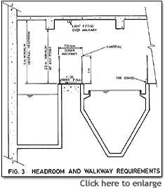
A general headroom of 3 m should be maintained for enclosed or underground STP with artificial ventilation. This may be reduced to 2.5 m at localized points, e.g. under beams. |
 |
| |
|
| 4.3 |
For enclosed STP, a minimum air volume of 14 m3 should be provided. Artificial ventilation should be provided with not less than 10 air changes per hour. Ventilation exhaust pipes should be carried up to a height not less than 1 m above the roof of the building at which the STP is located. |
|
| |
|
| 4.4 |
Access walkways of minimum 0.75 m clear width should be maintained within the STP for access to all areas requiring maintenance and operation. Walkways should have safety rails (preferably stainless steel) and toe boards. Walkways should be laid to a 1:25 crossfall to prevent ponding if of solid construction and they should not be obstructed by crossing pipework. |
| |
|
| 4.5 |
Where levels vary, staircases should be provided and not catladders or step irons. |
| |
|
| 4.6 |
All tanks should be provided with stainless steel ladder or step irons for access. Mild steel should not be used. Step irons should be spaced at 300 mm c/c horizontally and 250 mm c/c vertically. |
| |
|
| 4.7 |
If a tank has to be covered, stainless steel or aluminium alloy open mesh flooring should be used (aluminium should however not be used in chlorination facilities located in confined space). Open mesh flooring should be designed for 5kPA uniformly distributed load. |
| |
|
| 4.8 |
Provision of an emergency by-pass to the STP is not allowed under normal circumstances. |
| |
|
| 4.9 |
Fresh water taps for hoses and handwashing should be provided in the STP at convenient locations and should be shown on the drawings. |
| |
|
| 4.10 |
Electrical distribution boards and control panels should be installed in locations not liable to flooding and the locations shall be shown in the drawings. Panels should have a dehumidifying heater. |
| |
|
| 4.11 |
The control panel should incorporate a mimic/schematic diagram and all labels should be in both English and Chinese. All values, penstocks, pumps etc. should be appropriately labelled. |
| |
|
| 4.12 |
Hours run meters should be provided for all major equipment to record the total hours of operation. They should be of the non-resettable type. |
| |
|
| 4.13 |
Coarse screens should be provided to precede pumps. Fine screens should be placed downstream of equalization tanks equipped with air ejectors so as to minimize organic solids content in the screenings. |
| |
|
| 4.14 |
Mechanical screens should be the static type or of the type having the rakes moving in the bar openings and not on the bar. Either manual or mechanical by-pass screens should always be provided. The duty screen channel should have a high level overflow into the standby screen channel so that the flow diverts automatically through the standby screen in case the duty one is blocked. |
| |
|
| 4.15 |
Excessive screen channel width which results in shallow depth of flow should be avoided. In case of small developments where the smallest mechanical screen commercially available is still too wide, a manual screen may be used.
Bars of screen should be extended to the invert of the channel. For manual screens, consideration should be given to:
- access by operator;
- ease of removal of screenings by operator, including provision of suitable rake;
- draining of screenings;
- bagging and storage of screenings.
|
| |
|
| 4.16 |
A perforated/mesh type drain tray (of stainless steel or plastic material) should be provided to allow the screenings to drain prior to packaging. |
| |
|
| 4.17 |
Pump sumps (including equalization tanks) should be designed to limit the pump starts to not more than 10 times/hour. |
 |
| |
|
| 4.18 |
Electrical voltage for level sensors in pump sumps should not exceed 24 V to avoid electrical hazard. |
| |
|
| 4.19 |
High level alarms should be provided in all pump sumps. This should be in the form of visual and audio alarms connected to a suitable constantly manned location. |
|
| |
|
| 4.20 |
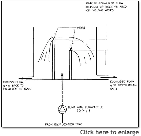
Pumps should be carefully chosen to correspond to the design duty point. Flow regulation tanks with control weir should be used if only bigger pumps are available. |
| |
|
| 4.21 |
Comminutors, especially the enclosed type, are discouraged as they often cause operational problems in the STP. |
| |
|
| 4.22 |
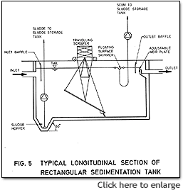
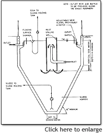
Sedimentation tanks should be designed either as rectangular horizontal flow tank, or as square/circular upward flow tank. For horizontal flow tank, the length to width ratio should not be less than 2. The use of tanks with length to width ratio between 1 and 2 should be avoided.
  |
| |
|
| 4.23 |
Upward flow sedimentation tanks should be provided with minimum 60o hopper wall slopes to facilitate easy sludge collection and removal. |
| |
|
| 4.24 |
Horizontal flow sedimentation tanks should be provided with a mechanical scraper system on a nominal floor slope, discharging to a sludge hopper. Twin tanks should preferably be used. If single tank is used, the scraper should be of the type that allows the underwater parts to be maintained without the need of shutting down the tank. |
| |
|
| 4.25 |
Adjustable weirs should be used for sedimentation tanks to enable fine levelling.
V-notch weirs should be used where wide flow variation occurs. The side-wall height should be not less than 1 m in order to avoid sludge carryover. The layout should be such that the inlet arrangement never becomes submerged in sludge. |
| |
|
| 4.26 |
A chamber should be provided at the final sedimentation tank outlet after the weir for installation of recirculation pump in the event that the actual initial flow is much lower than the design flow (see 4.1 above). |
| |
|
| 4.27 |
Sludge in sedimentation tanks should be removed as frequently as possible, at least once per day by a suitable sludge withdrawal device such as submersible sludge pumps, airlifts or valves. A scum removal device should also be provided. The sludge and scum removal device should have independent adjustable control. Inspection trough should be provided at the discharge end for inspecting the quality of sludge withdrawn so that adjustment to the withdrawal system may be made accordingly. |
| |
|
| 4.28 |
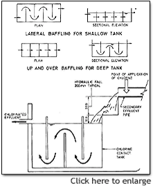
Chlorination facility should include a flash mixing device followed by a plug flow contact tank. Baffles should be provided in chlorination tanks to prevent short-circuiting. Lateral baffling should be used for shallow tanks and up-and-over baffling should be used for deep tanks. Dechlorination facility may be required in situations where the residual chlorine poses hazard to fisheries or shellfisheries. |
 |
| |
|
| 4.29 |
When tertiary treatment is required, disinfection (chlorination, ultra-violet radiation, ozonation, etc.) should be placed after tertiary treatment. |
| |
|
| 4.30 |
Sludge storage tanks should be provided with aerators when they are located in enclosed plant rooms to maintain the aerobic condition of the sludge. However, sludge storage tanks should preferably be ventilated separately to the exterior. Decanting facilities should be fitted to sludge storage tanks. Supernatant should be returned to the equalization tank. |
|
| |
|
| 4.31 |
Sludge pumps should be designed with positive suction head to minimize the possibility of clogging. |
| |
|
| 4.32 |
The diameter of the sludge draw-off pipework should be of a minimum diameter of 80 mm in order to prevent pipe blockages. |
| |
|
| 4.33 |
A sludge dewatering machine capable of attaining 30% w/w dry solids content for landfill disposal and a sludge tank for emergency storage of 14 days sludge volume should be provided. For small STP serving less than 100 population, it may be acceptable to provide only a sludge storage tank for wet disposal provided that:
- a storage tank capable of holding 60 days sludge volume be provided,
- vehicular access is maintained for desludging tankers,
- written confirmation is provided from a desludging contractor undertaking to carry out the work and specifying the ultimate disposal site for the wet sludge.
|
| |
|
| 4.34 |
An automatic flow measuring device with non-resettable type totalizer should be provided at suitable location for measuring the flow for STP serving a population of more than 50. |
| |
|
| 4.35 |
An easily accessible sampling point should be provided for taking samples of the treated effluent. |
| |
|
| 4.36 |
A minimum lighting intensity of 300 lux should be provided in the STP. Lights should be located where they are accessible for maintenance and replacement. |