Page
7.2 Legislative
Requirements and Evaluation Criteria
7.3 Study
Objectives and Methodology
7.8 Consequence
analysis for Storage and Transport of Explosives
7.9 Consequence
analysis for Use of Explosives
7.11 Hazard
Assessment for High Pressure Underground Town Gas Transmission Pipeline
7.12 Cumulative
Risk Assessment
LIST
OF TABLES
Table 7.1 Drill
and Blast – Explosives Requirements (Summary)
Table 7.2 Drill
and Blast – Typical Project Profiles
Table 7.3 Drill and
Blast – Initiating Systems
Table 7.4 Summary
of Explosives Deliveries and Transport Quantities.
Table 7.5 Scenarios
Considered in the QRA Study
Table 7.8 Potential
Loss of Life for Base Case
Table 7.9 Potential
Loss of Life for Worst Case
Table 7.10 Potential Loss
of Life for Base Case and Sensitivity Case
Table 7.12 Ignition
Probabilities from Cox, Lees and Ang Model
LIST
OF DIAGRAMS
Diagram 7.01
- Hong Kong Government Risk Guidelines
Diagram 7.02 - Schematic Diagram of QRA Process
Diagram 7.03 - Proposed Magazine Location and
Explosives Transport Route
Diagram 7.04 - Maximum Individual Risk Contours for
Delivery Route (Outdoor Population)
Diagram 7.05 - Maximum Individual Risk Contours for
Delivery Route (Indoor Population)
Diagram 7.06 - Individual Risk Contours for Magazine
(Outdoor Population)
Diagram 7.07 - Individual Risk Contours for Magazine
(Indoor Population)
Diagram 7.08 - F-N Curves for Storage, Transport and
Use of Explosives
Diagram 7.09 - F-N Curves Breakdown by Storage,
Transport and Use of Explosives
Diagram 7.10 - Framework for the Tolerability of
Individual Risk in IGEM
Diagram 7.11 - IGEM F-N Criterion Envelope
Diagram 7.12 - Individual Risk Contours for the HP
Underground Town Gas Transmission Pipeline
Diagram 7.13 - Societal Risk Curve for Construction
Stage
Diagram 7.14 - Societal Risk Curve for Operational
Stage
Diagram 7.15 - Societal Risk Curve with IGEM F-N
Criterion Envelope for Construction Stage
Diagram 7.16 - Societal Risk Curve with IGEM F-N
Criterion Envelope for Operational Stage
Diagram 7.17 - Cumulative Individual Risk Contours
Diagram 7.18 - FN Curves of Cumulative Risks
LIST
OF APPENDICES
Appendix 7.01 Hazard to Life Assessment for
Storage and Transport of Explosives
Appendix 7.02 Hazard to Life Assessment for the
Use of Explosives
Appendix 7.03 High Pressure (HP) Underground Town
Gas Transmission Pipelines
7
Hazard
to Life
7.1
Introduction
7.1.1
Background
7.1.1.1 This section of the EIA presents a summary of the analysis and findings of the Hazard to Life Assessment (also referred as Quantitative Risk Assessment (QRA)) undertaken for the proposed relocation of STSTW to caverns.
7.1.1.2 The proposed relocated STSTW will be located underneath Nui Po Shan within a granitic pluton, which comprises some of the freshest and hardest crystalline rocks in Hong Kong. The underground caverns vary in size, with proposed cavern span up to 32m (internal) and standard arch height to span ratio shall be 1:5. Approximately 3.7 million m3 (bulk volume) of rock will need to be excavated based on the proposed cavern layout. To ensure the timely completion of the Project, the only feasible, practical and economical method of excavation for such a large volume of rock is by drill and blast method with multiple blast faces. Drill and blast method is well established in Hong Kong, with lots of experiences for construction of tunnels and recently caverns greater than 24m in span. Other construction methods, i.e. drill and break, and the use of TBM are considered not suitable for cavern construction, taking into account the various cavern geometries, construction cost, programme and practicability. In particular, the required excavation dimensions are far in excess of the current capability of TBM technology. The excavation rates for drill and break method would fall way short of the necessary rate to complete the Project on time, being significantly smaller than the production rate of drill and blast method. Furthermore, in view of the large quantity of rock to be excavated, the provision of a magazine site would provide a more reliable explosive supply, allowing flexible blasting time and multiple faces under different excavation sequence, giving maximum tunnel production rates and the shortest construction period.
7.1.1.3 The alternative for project explosives magazine has been fully considered. In particular, utilizing the Kowloon Explosives Depot (KED), an existing government explosive storage facility as temporary explosive storage for the required quantities of Category 1 dangerous goods for the Project use. However, Mines Division (MD) of CEDD confirmed that KED is not able to provide round-the-clock service for the Contractor and as such not considered as a feasible option. Therefore, it is mandatory to select a suitable explosives magazine for the CSTW project to ensure the cavern excavation is on schedule and ultimately meeting the construction programme.
7.1.1.4 With reference to the EIA Study Brief, if storage, use and transport of explosives for rock blasting is required and the location of overnight storage of explosives magazine is in close vicinity to populated areas, a Hazard to Life Assessment is required.
7.1.1.5 The QRA for storage, transport and use of explosives relates to the construction stage of the Project, in which blasting activities are expected, would be presented in this section. Since no explosives will be handled during the operational stage, no QRA would be conducted for the operational stage.
7.1.1.6 The Hazard to Life assessment under this section of EIA, addresses, in particular, the following:
·
Storage of explosives (Category 1 dangerous goods, comprising
cartridged emulsion, detonating cord and detonators) at the proposed temporary
magazine including handling of
explosives within the magazine site;
·
Transport
of explosives to the delivery point; and
·
Use
of explosives including handling of explosives from the delivery point to the
blast faces.
7.1.1.7 In addition, there are several high pressure (HP) underground town gas transmission pipelines in the vicinity of the project boundary, potential hazard impacts from the gas pipelines are also required to be assessed.
7.1.1.8 Details of the QRA for the Project are presented in the following Appendices 7.01 to 7.03:
·
Appendix 7.01: Hazard to Life assessment for
storage and transport of explosives from the proposed magazine to the delivery
point;
·
Appendix 7.02: Hazard to Life assessment for the use of
explosives including the hazard impact assessment on town gas facilities; and
·
Appendix 7.03: Hazard to Life assessment for high pressure
underground town gas transmission pipelines.
7.2
Legislative Requirements and Evaluation
Criteria
7.2.1.1 The key legislation and guidelines that are considered relevant to the Hazard to Life Assessment for the Project are as follows:
·
Dangerous Goods Ordinance, Chapter 295;
·
Environmental Impact Assessment Ordinance
(EIAO), Chapter 499;
·
Institution of Gas Engineers and Managers
(IGEM); and
·
The EIA Study Brief (ESB-273/2014), Section
3.4.5.
7.2.2
EIAO Technical Memorandum (EIAO-TM)
7.2.2.1 The requirement for a QRA of projects that involve the storage, transport, use of dangerous goods and HP underground town gas transmission pipelines where a risk to life is a key issue with respect to the Hong Kong Government Risk Guidelines (HKRG) is specified in Section 12 of the EIAO-TM.
7.2.2.2
The
relevant authority for a QRA study relating to an explosives magazine storage
facility and the transport of the explosives is the EPD, as specified
in Annex 22 of the EIAO-TM; while for a QRA study relating to HP underground
town gas transmission pipelines the relevant authority is Electrical and
Mechanical Services Department (EMSD).
7.2.2.3 Annex 4 of the EIAO-TM specifies the Individual and Societal Risk Guidelines.
7.2.3
Hong Kong Government Risk Guidelines
(HKRG), EIAO-TM Annex 4
7.2.3.1 Individual risk (IR) is the predicted increase in the chance of fatality per year to an individual due to a potential hazard. The individual risk guidelines require that the maximum level of IR should not exceed 1 in 100,000 per year i.e. 1 x10⁻⁵ per year.
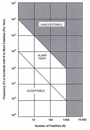
7.2.3.2 Societal risk expresses the risks to the whole population. The HKRG is presented graphically in Diagram 7.01. It is expressed in terms of lines plotting the frequency (F) of N or more deaths in the population from incidents at the installation. Two F-N risk lines are used in the HKRG that demark “acceptable” or “unacceptable” societal risks. The intermediate region indicates the acceptability of societal risk is borderline and should be reduced to a level which is “as low as is reasonably practicable” (ALARP). It seeks to ensure that all practicable and cost effective measures that can reduce risk will be considered.
Diagram 7.01 - Hong Kong Government Risk Guidelines
7.3
Study Objectives and Methodology
7.3.1.1 The objective of the QRA study is to assess the risk to life of the general public from the hazards that arise from the storage, transport, use of the explosives and HP underground town gas transmission pipelines that are required to facilitate the construction of the Project. The results of the QRA should then be compared with the HKRG.
7.3.1.2
The
detailed requirements
of the study are given in Section 3.4.5 of the EIA study brief. The main
requirements are:
·
To
identify hazardous scenarios associated with the storage, transport, use of
explosives and HP underground town gas transmission pipelines and then determine a set of
relevant scenarios to be included in the QRA;
·
To
execute a QRA of the set of hazardous scenarios determined and express
population risks in both individual and societal terms;
·
To
compare the individual and societal risks with the Criteria for Evaluating
Hazard to Life stipulated in Annex 4 of the EIAO-TM; and
·
To
identify and assess practicable and cost effective risk mitigation measures.
7.3.1.3
The
methodology of the hazard assessment should be consistent with previous studies
having similar issues.
7.3.1.4
The
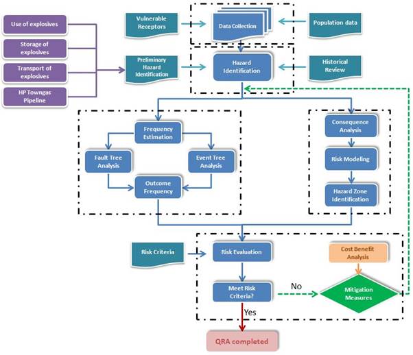
elements of the QRA are shown schematically in Diagram 7.02. It includes the following:
·
Collection
and review of relevant data for the proposed explosives magazine, the transport
from the magazines, the use of explosives at the works areas and HP
underground town gas transmission pipelines, as well as population and vulnerable receptors, such as slopes,
retaining walls etc., in the vicinity of storage, the tunnel and cavern construction, and the
proposed transport routes;
·
Hazard
identification. A review of
literature and accident databases was undertaken and updated. These formed the
basis for identifying all the hazardous scenarios for the QRA study;
·
Frequency
estimation. The frequencies, or the likelihood, of the various outcomes that
result from the hazards associated with the storage, transport and use of
explosives was taken
primarily from the ERM 2009 study [1] and ERM 2008 study [2], which has been
accepted by the relevant authorities. Where necessary, to consider specific
factors applicable for the Project, recent accident statistics, and to reflect the current knowledge
on the explosives’ properties, these frequencies were modified or updated
making reference, as far as possible to published references; such as the
previous Hong Kong studies, UK Health and Safety Executive (UK HSE),
United States Department of Defense (US DoD), Dutch Netherlands Organisation
for Applied Scientific Research (TNO), latest accident statistics from the
Transport Department (TD) and Fire Services Department (FSD), etc.;
·
For
all identified hazards, the frequency assessment has been documented and the
consequences were modelled;
·
The
consequence models employed in this study include:
o
Blast
effects including overpressure, flying debris, fireball, etc.: the Explosives
Storage and Transport Committee (ESTC) model [3], developed by the UK Health and Safety Commission (HSC).
Although, there have been a number of recent studies suggesting that the ESTC
(2000) models should be reviewed for applicability to explosive stores and
transport, these models are still the recommended models in the UK and adopted
in the ERM 2008 study [2].
o
Ground
shock / vibrations generated from an explosion: Ground vibration models
developed as part of the West Island Line (WIL) methodology [2]. Key sensitive
receivers were preliminarily screened based on the threshold limits of Peak
Particle Velocity (PPV), i.e. PPV ≥ 66mm/s for slope, PPV ≥ 100mm/s for
building and PPV ≥ 25mm/s for gas pipes. A detailed QRA was conducted as per
the WIL methodology [2] for those features with PPV exceeding the threshold
limits.
o
Thermal
and toxic effects: Probit equations for thermal impact and toxic impact are
used to estimate the consequence of any gas release from the HP underground
town gas transmission pipelines. Default sets of the probit equations in Phast
Risk 6.7 are adopted.
·
The
frequency model related to the transport and storage of explosives was taken
from the ERM 2009 study [1]. The frequency model related to the use of
explosives was taken from the ERM 2008 study [2] with human factor study and
Fault Trees updated to reflect the particular conditions of this study such as
blast face areas, number of sectors at the work face, number of production hole
and Maximum Instantaneous Charge (MIC) per production hole.
·
The
consequence and frequency data were subsequently combined using internationally
well recognised risk summation software. By summing up all hazard events,
individual risk and societal risk associated are obtained.
·
Finally,
the results from the risk assessment were compared to the EIAO-TM Criteria.
Recommendations have been made where required to ensure compliance with EIAO-TM
Criteria, relevant best practice, and to reduce the overall risk levels.
Diagram 7.02 - Schematic Diagram of QRA Process
7.3.1.5
The
methodology used in this hazard assessment is consistent with previous studies.
Details of the analysis can be found in Appendix 7.01, Appendix 7.02 and Appendix 7.03.
7.4
Facility Details
7.4.1
Project Overview
7.4.1.1 The layout of the cavern complex has been developed based on considerations of a number of disciplines, especially the sewage treatment process. The footprint consists of a series of parallel caverns aligned along the long axis of the complex. The process caverns have a generally consistent excavated pan of around 32m but the height of the caverns varies dependent on the sewage treatment process being undertaken in each cavern.
7.4.1.2 Two access tunnels are proposed to connect to the caverns. One of the tunnel portals is located at the junction of Mui Tsz Lam Road and A Kung Kok Street and the other portal is located close to the current DSD site on Mui Tsz Lam Road. A ventilation shaft is also proposed at the southwest side of the caverns.
7.4.2
Statutory / Licensing Requirements
7.4.2.1 The statutory / licensing requirements with respect to the explosives (Category 1 Dangerous Goods) or the oxidizing substances (Category 7 Dangerous Goods) which are used to prepare explosives at the construction work area as well as relevant government departments / authorities’ advice and practice on the proposed transport and storage of explosives for the blasting activities, are summarized below.
Category 1 Explosives and Blasting
Agents
· Responsible authority: The Commissioner of Mines
· Applicable regulations / guidance notes:
-
Supply of detonators
and cartridged emulsion explosives (under the Dangerous Goods (General)
Regulations Cap. 295B);
-
Approved explosives for
blasting in Hong Kong (under the Dangerous Goods (General)
Regulations Cap. 295B);
-
Blast design (under the
Dangerous Goods (General) Regulations Cap. 295B);
-
Blast loading and
execution (under the Dangerous Goods (General) Regulations Cap. 295B);
-
Removal of explosives
(under Regulation 4 of the Dangerous Goods (General) regulations Cap. 295B);
-
Approval of an
explosives carrying vehicle (under CEDD’s “Guidance Note on Requirements for
Approval of an Explosive Delivery Vehicle”);
-
Explosives carrying
vehicle design features and safety requirements (under CEDD’s “Guidance Note on
Requirements for Approval of an Explosive Delivery Vehicle”);
-
Explosive magazine
(under CEDD’s document “How to Apply for a Mode A Explosives Store Licence”);
-
Explosives produced at
site (under Regulation 31A of the Dangerous Goods (General) Regulations Cap.
295B);
-
Explosives load per
truck (in accordance with the Removal Permit issued under the Dangerous Goods (General)
Regulations Cap. 295B);
- Guidance
Notes on How to Apply for a Blasting Permit; and
- Guidance
Note on Licensing of a Manufacturing Unit for Explosives at a Blast Site.
Category 7 Strong Supporters of Combustion
· Responsible authority: Fire Services Department
· Applicable regulations:
-
Storage of oxidizing
agents (under Dangerous Goods (General) Regulations Cap. 295B)
7.4.2.2 This Project will generally use bulk emulsion as the main blasting agent. Bulk Emulsion is delivered to site as an oxidizing agent, and it is converted into an explosive by the addition of a gassing agent at the blast face, immediately before inserting it into the blast holes. Only cartridged emulsion, detonators and detonating cord will be transported to site as Category 1 Dangerous Goods. Therefore, the storage and transport requirements for explosives (i.e. Category 1 dangerous goods) are the minimum required quantities for the Project.
7.4.3
Temporary Storage Magazine Details
7.4.3.1
A new temporary surface
magazine site is proposed to be constructed at the end of A Kung Kok Shan Road.
The design, construction and operation of the magazine will comply with the
general requirements from the Commissioner of Mines [5].
7.4.3.2
The magazine is
designed to store sufficient quantities of explosives for two days so as to
allow blasting to be carried out 24 hours per day and provide a buffer in the
event of delivery interruption to the magazines by MD.
7.4.3.3
The magazine is located
in area of low population density. It comprises 3 magazine structures with each
storing maximum 500kg of explosives.
7.4.3.4
To ensure the security
of explosive, security fence including overhang covered in barbed wire will
surround the Mode A Explosive Store.
Security guards will be on duty 24 hours, with a guard hut located at
the entrance. The guard hut will be provided with a register of authorised
persons who are permitted to enter the compound. CCTV system will also be
installed to provide 24 hours surveillance and video record. Each of the
magazine buildings is a single-storey, detached and bunded structure, which is
fenced and secured in accordance with the Commissioner of Mines’ requirements.
Details of the requirements are defined in the CEDD document “How to Apply for
a Mode A Explosives Store Licence” [5].
Surface road access suitable for 11-tonne trucks is also provided for
delivery of explosives.
7.4.3.5
The quantities of
explosives in kg mentioned in the report are represented in gross weight,
unless they are clearly specified as Trinitrotoluene (TNT) equivalent kg.
7.4.3.6 The scenario of not having a magazine has also been studied. The blasting works, hence the construction programme, will be substantially affected without the provision of a magazine site due to the resources constraints of the MD of CEDD in delivery of explosives. Based on our preliminary assessment, the construction time of the Project will have to be prolonged by 10 years to 2037. The existing STSTW will be over 50 years old by 2037 which is well beyond its design life. Unless significant rehabilitation is carried out to the existing STSTW in the near future, it is unlikely that the STSTW could provide the required services in terms of treatment capacity/removal efficiency by 2037. It is considered not cost effective to spend significant amount to rehabilitate the existing STSTW which would be relocated to caverns soon after the rehabilitation.
7.4.4
Transport Route Details
7.4.4.1 MD will deliver explosives to the magazine on a daily basis, from where explosives will be transferred to the work areas by the contractor(s) for the daily or twice-daily blasts depending on requirements for construction. Loads will be limited to a maximum of 200 kg per truck or less in accordance with the Removal Permit issued by MD.
7.4.4.2 The explosives will be delivered from the magazine, via a site access road to A Kung Kok Shan Road, A Kung Kok Shan Road, A Kung Kok Street and Mui Tsz Lam Road to the work areas as shown in Diagram 7.03. The total length of transport route is around 4.1km.
Diagram 7.03 - Proposed Magazine Location and Explosives
Transport Route

7.4.4.3 According to the current construction programme, a maximum of 3 deliveries per day will be required. In addition to cartridged emulsion and detonating cord, detonators will also be transported. Cartridged emulsions and detonating cords will be transported in the same vehicle while detonators will be transported in a separate explosives carrying vehicle.
7.4.4.4 The explosives carrying vehicles for delivery of explosives from the magazine site to the construction site boundary, used as the basis for this QRA, will have the following key safety features according to “Guidance Note on Requirements for Approval of an Explosives Delivery Vehicle” published by CEDD Mines Division:
·
Manual
fuel isolation switch;
·
Forward
mounted exhaust with spark arrestor;
·
All
electrical wiring or electrical devices will be shrouded in fire resisting
conduits;
·
Fuel
tank will be protected from accidental damage, and designed to prevent
accumulation of spilt fuel on any part of the vehicle;
·
Two
fire extinguishers will be mounted on an easily accessible position on the
vehicle;
·
Fire
resistant material will be fitted between the wheel arches and the goods
compartment;
·
Lockable
wood lined steel or aluminium receptacles mounted on the vehicle
tray; and
·
Fold
down / up explosives warning signs and rotating flashing light.
7.4.4.5 In addition, a fire screen will be fitted between the cab and the load compartment and between the load compartment and the chassis.
7.4.4.6 There will only be one delivery point from magazine to construction site. For the blasting of ventilation shaft, explosives will be delivered to blasting site by manual transfer due to short distance away from magazine site. Manual transfer to ventilation shaft is considered as onsite transport of explosives and discussed in Section 3.4 of Appendix 7.02.
7.4.5
Use of Explosives Details
7.4.5.1 Explosives will be used for the construction of the cavern, access tunnels, ventilation adit and ventilation shaft.
7.4.5.2 The initial excavation of the tunnels will be carried out by mechanical methods. Drill and blast excavation as top heading and bench will then be adopted for initial blasting, followed by full face excavation if ground conditions are suitable. Blasting cover protection will be provided to all shaft / portal prior to blasting being carried out.
7.4.5.3 The following safeguards will be implemented during blasting:
·
Vibration
blast Monitoring – It is required that every in Hong Kong should be monitored
to record the blast induced ground vibration. A blast engineer is responsible
for ensuring that the vibration levels at all identified sensitive receivers
are monitored for each blast and the vibration level in terms of PPV are
recorded.
·
Initial
Blasts – Initial blasts will be conducted with cartridged emulsion explosives,
and will be carried out for the first series of blasts for the tunnels and
different areas of the Project. The initial blasts are to demonstrate that the
different types of blasting are safe, and the blasting monitoring and control
procedures are effective.
·
Advance
Notice of Blasts – Highly visible warning notices / signals will be posted near
the intended blasting locations to warn the public that blasting will take
place.
·
Safety
Management System – The contractor(s) is required by Law to have a
comprehensive Safety Management System, and the system should be implemented
and supervised by on-site safety teams. Independent third party auditors will
make annual checks of documentation and safety records.
·
Public
Safety Measures – Site hoarding, security guards, and warning signage shall be
installed at both the construction site and magazine site as public safety
measures. Resident Engineers should organize District Council Meetings and
Public Relations Programmes during the construction project. Also, there will
be safety training and inspection provided by Construction Industry Council
(CIC) and Labour Department.
7.4.6
Base Case and Worst Case for Quantitative
Risk Assessment
7.4.6.1 The actual construction programme will depend on the detailed design and appointed contractor(s). It may also depend on the actual achievable progress rates which may vary due to specific site conditions (e.g. geology). To consider the uncertainty in the envisaged construction programme, a Base Case, which accounts for expected programme variations, and a Worst Case, which presents the worst programme scenario, have been considered for the assessment.
7.4.6.2
The blasting activities together with the
required amount of explosives is summarized in Table 7.1.
The actual amount of explosives (i.e. Category 1 dangerous goods) is calculated
based on different tunnels and caverns profiles described in Table
7.2 and the Initiating Systems listed in Table 7.3.
Note that both cartridged emulsion and detonating cord may be used as part of
the initiating system, and also as part of the main blasting explosives (in the
perimeter holes). Detonators are used solely as part of the initiating system.
Table 7.1 Drill
and Blast – Explosives Requirements (Summary)
|
Works Area |
Delivery Point |
Blast Face |
Approximate No. of Blasts |
Explosive Load (kg/ blast) |
|
Single Access Tunnel Top
Heading |
Mui Tsz Lam Road |
Access Tunnel |
40 |
76.1-433.5 |
|
Single Access Tunnel Bench |
Mui Tsz Lam Road |
Access Tunnel |
40 |
21.7-178.5 |
|
Full Access Tunnel Top
Heading |
Mui Tsz Lam Road |
Access Tunnel |
202 |
70.9-382.5 |
|
Full Access Tunnel Bench |
Mui Tsz Lam Road |
Access Tunnel |
101 |
25.1-255 |
|
Secondary Access Tunnel Top
Heading |
Mui Tsz Lam Road |
Access Tunnel |
81 |
70.9-382.5 |
|
Secondary Access Tunnel
Bench |
Mui Tsz Lam Road |
Access Tunnel |
81 |
20.5-453 |
|
Ventilation Shaft |
A Kung Kok Shan Road |
Ventilation Shaft |
36 |
28.8-100 |
|
Ventilation Tunnel |
Mui Tsz Lam Road |
Ventilation Tunnel |
198 |
51.5-255 |
|
Branch Tunnel Top Heading |
Mui Tsz Lam Road |
Tunnel |
114 |
65.2-326.4 |
|
Branch Tunnel Bench |
Mui Tsz Lam Road |
Tunnel |
114 |
19.7-140.3 |
|
Cavern Top Heading |
Mui Tsz Lam Road |
Cavern |
1516 |
70.9-382.5 |
|
Cavern Bench |
Mui Tsz Lam Road |
Cavern |
1516 |
38.2-510 |
Table 7.2 Drill
and Blast – Typical Project Profiles
|
Tunnels/ Caverns Profile Description |
Section Area (m2) |
No. of production holes |
No. of perimeter holes |
Cartridged Emulsion (kg) |
Detonating Cord (kg) |
Detonators (kg) |
|
Single Access
Tunnel Top Heading (CE) |
170 |
365 |
85 |
423.3 |
10.2 |
0.45 |
|
Single Access
Tunnel Top Heading (BE) |
170 |
160 |
85 |
45.5 |
30.6 |
0.25 |
|
Single Access
Tunnel Bench (CE) |
70 |
150 |
20 |
176.1 |
2.4 |
0.17 |
|
Single Access
Tunnel Bench (BE) |
70 |
68 |
20 |
14.5 |
7.2 |
0.088 |
|
Full Access Tunnel
Top Heading (CE) |
150 |
330 |
80 |
372.9 |
9.6 |
0.41 |
|
Full Access Tunnel
Top Heading (BE) |
150 |
145 |
80 |
42.1 |
28.8 |
0.23 |
|
Full Access Tunnel
Bench (CE) |
100 |
300 |
20 |
252.6 |
2.4 |
0.32 |
|
Full Access Tunnel
Bench (BE) |
100 |
95 |
20 |
17.9 |
7.2 |
0.12 |
|
Secondary Access
Tunnel Top Heading (CE) |
150 |
330 |
80 |
372.9 |
9.6 |
0.41 |
|
Secondary Access
Tunnel Top Heading (BE) |
150 |
145 |
80 |
42.1 |
28.8 |
0.23 |
|
Secondary Access
Tunnel Bench (CE) |
60 |
150 |
20 |
150.6 |
2.4 |
0.17 |
|
Secondary Access
Tunnel Bench (BE) |
60 |
58 |
20 |
13.3 |
7.2 |
0.078 |
|
Ventilation Shaft (CE) |
50 |
150 |
40 |
96.8 |
3.2 |
0.19 |
|
Ventilation Shaft (BE) |
50 |
70 |
40 |
20.8 |
8 |
0.11 |
|
Ventilation Tunnel (CE) |
100 |
214 |
60 |
247.8 |
7.2 |
0.27 |
|
Ventilation Tunnel (BE) |
100 |
95 |
60 |
21.6 |
21.6 |
0.16 |
|
Branch Tunnel Top
Heading (CE) |
128 |
280 |
76 |
317.3 |
9.1 |
0.36 |
|
Branch Tunnel Top
Heading (BE) |
128 |
120 |
76 |
37.8 |
27.4 |
0.20 |
|
Branch Tunnel Bench
(CE) |
55 |
140 |
20 |
137.9 |
2.4 |
0.16 |
|
Branch Tunnel Bench
(BE) |
55 |
52 |
20 |
12.5 |
7.2 |
0.072 |
|
Cavern Top Heading
(CE) |
150 |
330 |
80 |
372.9 |
9.6 |
0.41 |
|
Cavern Top Heading
(BE) |
150 |
145 |
80 |
42.1 |
28.8 |
0.23 |
|
Cavern Bench (CE) |
200 |
400 |
20 |
507.6 |
2.4 |
0.42 |
|
Cavern Bench (BE) |
200 |
200 |
20 |
31 |
7.2 |
0.22 |
Note 1: The following abbreviations apply: CE - Cartridged Emulsion, BE – Bulk Emulsion Explosives
Note 2: Typical
project profiles given for an assumed pull length of 4.5m. For some tunnel
sections, this is not achievable due to the proximity of sensitive receivers.
Table 7.3 Drill and Blast – Initiating Systems
|
Explosive Type |
Quantity per
Production/ Perimeter Hole |
|
Cartridged emulsion |
0.125 kg (125 g per cartridged emulsion) 1 |
|
Detonating cord |
0.08 kg/m based on density of 0.04 kg/m (40
g/m) |
|
Detonator |
0.001 kg (0.9 g each) |
Note 1: For
blast where MIC is lower than 2 kg and Bulk Emulsion cannot be used; 0.208 kg
cartridged types may be used.
Base Case for the
Hazard to Life Assessment
7.4.6.3 When three blasts in two days scenario is expected, consumption of explosives is estimated to be 540kg in total per day. Delivery frequency will be 3 times daily for explosives (i.e. Category 1 dangerous goods) with maximum loading of 200kg per truck. Detonators shall be transported in a separate explosives carrying vehicle.
7.4.6.4 From a yearly basis point of view, blasting will be carried out 25 days per month on average, and the annual number of explosives delivery is thus estimated to be 900. The assessment year of the project is 2022.
Table 7.4 Summary
of Explosives Deliveries and Transport Quantities
|
Delivery Point |
Explosive Deliveries in Peak Delivery Period (trips/year) |
Peak Transport Quantity (kg/trip) |
|
Mui Tsz Lam Road Portal |
900 |
200 |
Worst Case for the
Hazard to Life Assessment
7.4.6.5 There is possibility that the actual construction programme differs from the envisaged construction programme due to construction uncertainties or different construction methods adopted by different contractors. Such a case may result in more delivery trips and return trips may be made. Overall, a 20% increase in the number of deliveries compared to the base case scenario may result in the worst case based on previous project experience.
7.5
Population Data
7.5.1.1 Population in the vicinity of the explosives magazines is estimated based on the site surveys and information gathered from Geographic Information System (GIS) database and aerial maps. There is no known (current or future) buildings or any other structures in the hazard zone of the proposed Magazines.
7.5.1.2 Population data used for the transport risk assessment have been collected by a combination of site surveys, Base District Traffic Model (BDTM), Annual Traffic Census (ATC), and Centamap. For areas where information is not available, information will be collected by various methods such as site surveys. Four types of population have been considered which include:
· Building population;
· Road population;
· Train population; and
· Pedestrian population on footpaths and pavements next to the delivery route.
7.5.1.3 The population data adopted in the QRA is detailed in Appendix 7.01.
7.6
Hazard
Identification
7.6.1
General
7.6.1.1 Hazard identification consisted of a review of the following:
· Explosives properties;
· Scenarios presented in previous relevant studies;
· Historical accidents; and
· Discussions with explosives and blasting specialists.
7.6.2
Hazards of Explosives
7.6.2.1 Explosives present a hazard to both property and people. This hazard manifests itself in the following ways:
· Blast and pressure wave;
· Flying fragments or missiles;
· Thermal radiation; and
· Ground shock.
7.6.2.2 In the case of explosions, the biggest damage is usually caused by the blast effects. The blast and pressure waves can cause injury to sensitive human organs such as the ears and lungs. However, considerable overpressures are required for fatalities to occur, and consequently people need to be fairly close to the scene of the direct explosion effects to be significant.
7.6.2.3 Other effects due to the blast or overpressure are associated with damage to buildings and other structures/ objects or the impact of debris and fragments from damaged building structure, and the vehicle or container in which the explosives are held. Moreover, injury may occur when people are displaced or swept away, or due to the violent movement of internal organs within the body.
7.6.2.4 An explosion may result in the formation of a short duration fireball since the fuel content of the emulsion is oxidised. However, although it is generally the case that the thermal hazards from an explosives detonation event is of less concern than the blast and fragment hazards.
7.6.3
Review of Incidents
7.6.3.1 A review of reported safety incidents involving storage, transport and disposal of explosives (in industrial applications) was carried out. Records were retrieved mainly from the UK HSE’s Explosives Incidents Database Advisory Service (EIDAS) [6], US Mine Safety and Health Administration (MHSA) [7] and Western Australia’s Department of Consumer and Employment Protection (DOCEP) [8]. The records provided are also supplemented with information obtained from various sources. An analysis of accident data is provided in Section 5 and Section 6 of Appendix 7.01.
7.6.4
Scenarios for Hazard Assessment
7.6.4.1 The scenarios considered in this QRA are summarized in Table 7.5.
Table 7.5 Scenarios
Considered in the QRA Study
|
Tag |
Scenario |
|
Storage of Explosives |
|
|
ST01 |
Detonation of
full load of explosives in one store in A Kung Kok Shan site. |
|
Transport of Explosives |
|
|
ST02 |
Detonation of
full load of explosives in one contractors’ truck on public roads from
magazine site to construction site boundary. |
|
Use of Explosives |
|
|
U01 |
Higher than expected
vibrations generated at the blast face due to human errors or other reasons
such as manufacturing defects causing deviation from the confirmed design. |
|
U02 |
Vibrations due to the
detonation of a full load of explosives within the tunnel/ ventilation shaft
while transferring explosives to the appropriate blast site. |
|
U03 |
Blast effects including
debris and overpressure due to the detonation of a full load of explosives
within the tunnel/ ventilation shaft. Blast effects are modelled at the
portal ignoring attenuation factors along the tunnel. |
|
U04 |
Blast and vibration effects
due to accidental explosion of the full load of explosives during onsite
transport of explosives. |
7.7
Frequency Analysis
7.7.1
Introduction
7.7.1.1 Deflagration or detonation explosion may occur during the transportation of explosives from the magazine to the construction site. This accidental explosion can be caused by spontaneous fire (non-crash fire), fire after a vehicle crash (crash fire), impact initiation in crash (crash impact) or spontaneous explosion during the normal condition of transport which may occur if the cargo load contains ‘unsafe explosives’.
7.7.1.2 In this study, a fault tree has been developed to assess the overall explosion frequency as applicable to the Project contractors’ trucks based on the latest information available on the explosives properties, vehicle incident frequencies provided by the TD and FSD, and the specific explosive transport vehicle design and operation to be used as part of the Project. The details of the frequency assessment are provided in Section 6 of Appendix 7.01.
7.7.2
Frequency Analysis for Storage of
Explosives
7.7.2.1 The overall initiating event frequency within the storage magazine is based upon the UK HSE recommended value of 1 × 10⁻⁴ per storehouse year. Additional risk due to manual transfer of explosives, lightning strike, aircraft crash, hill / vegetation fire, earthquake and other site specific considerations for the Project were also considered but their contribution was negligible (see Section 6 of Appendix 7.01).
7.7.3
Frequency Analysis for Transport of
Explosives
7.7.3.1 Based on Hong Kong vehicle accident data, the frequencies of explosives initiation during road transport are estimated as 7.69 x 10⁻¹⁰/km for the truck on non-expressway using a fault tree approach [1]. The fault tree model has considered the frequencies of non-crash fire, crash fire, crash impact and unsafe explosive. Adjustment factors were applied to the model to account for the probabilities of explosive initiation due to thermal stimulus or crash impact.
7.7.4
Frequency Analysis for Use of Explosives
7.7.4.1 A failure mode analysis was carried out to determine the potential failure modes associated with the use of explosives, leading to higher than expected vibration. The scenario of 2 or more MIC detonated at the same time was identified for the risk assessment. Fault Tree Analysis (FTA) was conducted, in conjunction with human factor assessment, to determine the occurrence frequency of 2 or more MIC detonated at the same time (see Section 4 of Appendix 7.02). The derived frequencies are increased by 25% to account for actual scenarios. Table 7.6 summarizes the overall frequency for failure scenarios leading to higher than expected vibrations for the Project.
Table 7.6 Overall
Frequency for Failure Scenarios Leading to Higher than Expected Vibration
(Scenario U01 in Table 7.5)
|
Sections |
Occurrence Frequency for multiple MIC detonated at the same time
(Occurrence per project) |
||||
|
2 MIC |
3 MIC |
4 MIC |
5 MIC |
6 MIC |
|
|
Access Tunnels and Ventilation Tunnel |
1.36E-02 |
1.15E-04 |
1.17E-06 |
1.17E-06 |
1.17E-06 |
|
Ventilation Shaft |
5.06E-04 |
4.28E-06 |
4.35E-08 |
4.35E-08 |
4.35E-08 |
|
Cavern |
4.26E-02 |
3.61E-04 |
3.67E-06 |
3.67E-06 |
3.67E-06 |
7.7.4.2
For the Worst Case scenario, the overall number
of blasts is increased by 20% to account for potential deviation from the
envisaged construction programme.
7.7.4.3 For an accidental initiation of the full load explosives when explosives are delivering from the delivery point to the blast faces, a failure frequency of 7.69×10⁻¹⁰ per truck-km per year was used.
7.7.4.4 Since the transport length within the tunnels will vary as the blasting proceeds, the average transport length was assumed as half of the tunnel length for all deliveries in accordance with the WIL Study [2]. The overall transport length comprises the length of the access tunnel combined with half of the cavern length. The frequencies of accidental explosion during delivery to blast sites are given in Table 7.7.
Table 7.7 Frequency
of Accidental Explosion due to Detonation of Full Load of Explosives during
Delivery to Blast Site (Scenarios U02 to U04 in Table 7.5)
|
Delivery
Scenario |
Descriptions |
Frequency (/
year) |
|
D01 |
Initiation of explosives during delivery from delivery point at Mui Tsz Lam Road to Main Portal |
4.84E-08 |
|
D02 |
Initiation of explosives during delivery from portal to blast site through main access tunnel. |
9.34E-08 |
|
D03 |
Initiation of explosives during delivery from Ventilation Shaft Portal to Ventilation Shaft Blast Site. |
1.33E-08 |
7.7.4.5 For accidental initiation of explosives occurring within the tunnel (Delivery Scenario D02), the blast effects are considered at the tunnel portal, while the vibration effects are considered at the truck location in accordance with the WIL Study [2]. Vibration effect is only considered in Delivery Scenario D02 and D03 as the delivery from portal to blast site is in confined space.
7.7.4.6 For the Worst Case scenario, the number of delivery is increased by 20% to account for potential deviation from the envisaged construction programme.
7.8
Consequence analysis for Storage and
Transport of Explosives
7.8.1.1 The probability of fatality due to blast over-pressure, have been estimated using the method detailed by the UK HSE’s ESTC [3]. The fatality contours are calculated at 90%, 50%, 10%, 3% and 1% fatality. Details of the model and the results are given in Section 7 of Appendix 7.01.
7.8.1.2 Special features such as slopes or gas pipes along the transport routes or near the magazine sites were identified with respect to the potential secondary hazards. These aspects of risk were evaluated separately, and were found either insignificant or already covered by applying the blast overpressure-fatality model (i.e. ESTC model [3]).
7.9
Consequence analysis
for Use of Explosives
7.9.1.1 The use of blasting to excavate tunnels and carven in rock presents a hazard to both property and people. Three different degrees of consequences were considered in this study, and details are given in Appendix 7.02.
· Primary effect – Ground vibration and blast effects;
· Secondary effect – Effects associated with building collapse, slope failure, and impact of debris and fragments from damaged features;
· Tertiary effect – Landslide and boulder fall etc.
7.9.1.2 The probability of fatality due to blast effects are estimated by using the ESTC model [3]. The probability of fatality due to possible damage / failure of building or slope, due to ground vibration are modelled using methods detailed in the Hong Kong CEDD Geo Reports [11] and WIL Study [2]. The fatality contours are calculated at 90%, 50%, 10%, 3% and 1% fatality.
7.9.1.3 Ground vibration levels at a given receptor depend on the separation distance between the receptor and the blasting point. Method published in the Hong Kong CEDD Geo Reports [11] is adopted to estimate the ground vibration levels.
7.9.1.4 Secondary and tertiary effects, if any, are modelled consistently with the WIL methodology [2].
7.10
Risk Summation
7.10.1
Overview
7.10.1.1 Consequences and their corresponding frequencies are summed up for the whole Project using Phast Risk 6.7. By summing up all hazard events, Individual Risk and Societal Risk associated with the identified hazardous scenarios are obtained and compared with the criteria set out in Annex 4 of the EIAO-TM to determine their acceptability.
7.10.2
Individual Risk Results
7.10.2.1 The individual risk (IR) contours associated with the Project are shown in Diagram 7.04, Diagram 7.05, Diagram 7.06 and Diagram 7.07. In the Diagrams, the ‘indoor’ refers to the population located inside buildings, and the ‘outdoor’ refers to the population located outside buildings, i.e. in open area. At the same distance from a potential explosion, persons located inside buildings are more vulnerable to explosion than persons located outside buildings as they are exposed to more hazards such as debris from broken windows, etc. This explains a higher individual risk for indoor population.
7.10.2.2 For the delivery routes, the IR data represent the highest individual risk, occurring on the road in the same lane as the explosives carrying vehicle. It is observed that the maximum IR is less than 1×10⁻⁶ per year. This is a low risk when compared to HKRG which require the offsite IR from a fixed installation to be below 1×10⁻⁵ per year.
7.10.2.3 The Project magazine is located in remote area and with a gate at A Kung Kok Shan Road where the entrance of the magazine access road is located. The IR contours of 1×10⁻⁵ per year extend outside the site boundary. However, there will be no non-construction population entering the magazine access road. Therefore, no public will be exposed to an individual risk of 1×10⁻⁵ per year, and thus the level of individual risk associated with storage of explosives should be acceptable.
Diagram 7.04 - Maximum Individual Risk Contours for
Delivery Route (Outdoor Population)

Diagram 7.05 - Maximum Individual Risk Contours for
Delivery Route (Indoor Population)

Diagram 7.06 - Individual Risk Contours for Magazine
(Outdoor Population)

Diagram 7.07 - Individual Risk Contours for Magazine
(Indoor Population)

7.10.3
Societal Risk Results
7.10.3.1 The societal risk results for explosives storage, transport and use have been combined to produce the overall societal risk results for the base case and the worst case (see Diagram 7.08). The breakdown of F-N curves by storage, transport and use of explosives for base case is shown in Diagram 7.09.
7.10.3.2 The Base Case represents the risks associated with the envisaged blasting programme; while the Worst Case represents the maximum risks associated with the worst blasting scenario. It can be seen that both risks lie in the lower ALARP region.
7.10.3.3 The F-N curves for both Base Case and Worst Case are within the ALARP Region as per EIAO-TM. Therefore, mitigation measures need to be considered to reduce the risk. The ALARP assessment is provided in Section 9 of Appendix 7.01.
7.10.3.4 The Potential Loss of Life (PLL) for the Base Case and the Worst Case are given in Table 7.8 and Table 7.9 respectively. The PLL for this project has been evaluated at 2.84×10⁻⁵ per year. The maximum PLL value for the Project is estimated at 3.40×10⁻⁵ per year, which is obtained from the Worst Case. It is observed that there is no risk from the magazine as it is located in a remote area with a gate at the entrance of the magazine access road. Risk associated with use of explosives is relatively low compared to the transport risks. Indeed, the risk related to use of explosives is low due to the stringent monitoring and controls in place throughout the blasting process.
Diagram 7.08 - F-N Curves for Storage, Transport and Use
of Explosives

Diagram 7.09 - F-N Curves Breakdown by Storage, Transport
and Use of Explosives

Table 7.8 Potential
Loss of Life for Base Case
|
Case: Base Case |
PLL (per year) |
Contribution (%) |
|
Storage of Explosives |
||
|
Detonation of full load of explosives in one store in A
Kung Kok Shan site |
0 |
0 |
|
Transport of Explosives |
|
|
|
A Kung Kok Shan Road to Mui Tsz Lam Road |
2.76E-05 |
97 |
|
Use of Explosives |
|
|
|
Full load detonation of explosives during transport from
delivery point to portal |
3.05E-07 |
1 |
|
Full load detonation of explosives during transport from
portal to blast face |
4.68E-07 |
2 |
|
Higher than expected ground vibration during construction
of cavern, tunnels and shaft causing |
2.61E-08 |
~0 |
|
Total |
2.84E-05 |
100 |
Table 7.9 Potential Loss of Life for Worst Case
|
Case: Worst Case |
PLL (per year) |
Contribution (%) |
|
Storage of Explosives |
||
|
Detonation of full load of explosives in one store in A
Kung Kok Shan site |
0 |
0 |
|
Transport of Explosives |
|
|
|
A Kung Kok Shan Road to Mui Tsz Lam Road |
3.31E-05 |
97 |
|
Use of Explosives |
|
|
|
Full load detonation of explosives during transport from
delivery point to portal |
4.06E-07 |
1 |
|
Full load detonation of explosives during transport from
portal to blast face |
5.62E-07 |
2 |
|
Higher than expected ground vibration during construction
of cavern, tunnels and shaft causing |
3.14E-08 |
~0 |
|
Total |
3.41E-05 |
100 |
7.10.4
ALARP Assessment
7.10.4.1 Since the risks posed by the Project, for both cases considered, are within the ALARP region specified in EIAO-TM Annex 4, this implies that risk reduction measures and / or alternative options should be explored for the Project.
7.10.4.2 It was found that the risks arising from explosives transport are much more significant than that of explosives storage; hence the ALARP assessment focuses on the transportation aspects of explosives.
7.10.4.3 Where the risk falls into the ALARP region, the risks associated with each probable hazardous event should be reduced to a level ‘As Low As Reasonably Practicable’. This firstly requires the identification of any ‘practicable’ options regardless of their cost. A mitigation option is considered ‘practicable’ if an engineering solution exists and can be implemented on the project regardless of the cost without affecting the project construction programme. Secondly, the extent to which the risk should be reduced is usually measured as a trade-off between the risk reduction, i.e. the safety benefits and the cost of the risk reduction measure. A mitigation option is considered ‘reasonable’ if the cost of implementing the option is not grossly disproportionate to the achieved safety benefits.
7.10.4.4 Risk mitigation measures may take the form of engineered measures, controls in the zones most impacted by the hazardous scenarios presented by this Project, or operation and procedural controls.
Approach to ALARP
Assessment
7.10.4.5 The approach consists of identifying potential justifiable mitigation measures, assessing their practicability for this project and evaluating their cost and comparing with the safety benefits of implementing the measures. Combinations of mitigation measures are also considered.
7.10.4.6 The safety benefits are calculated by the following equation:
Safety benefits = Value of Preventing a Fatality x Aversion Factor x Reduction in PLL value x Design Life of mitigation measure
7.10.4.7 The Value of Preventing a Fatality (VPF) represents the monetary value that the society is willing to invest to prevent a fatality, i.e. the tolerability of risk by the society. The VPF value is taken as HK$33M per person in this project. The VPF value is adjusted according to different level of risks to reflect people’s aversion to high risks with probability of multiple fatalities [1]. The application of the aversion factor of this study follows the EPD’s Technical Note on Cost Benefit Analysis developed in 1996. The aversion factor is calculated on a sliding scale from 1 (risks at the lower boundary of the ALARP region of the Risk Guidelines) up to a maximum of 20 (risks at the upper boundary of the ALARP region of the Risk Guidelines). The adjusted VPF using the aversion factor of 20 is HK$660M. This is the value to measure how much the society is willing to invest to prevent a fatality, where there is potential for an event to cause multiple fatalities.
7.10.4.8 The cost of implementing potential justifiable mitigation measures is checked against the Maximum Justifiable Expenditure first. The value of Maximum Justifiable Expenditure will be calculated by assuming the risk is reduced to zero. Justifiable mitigation measures will be further analysed considering the actual reduction in PLL in the calculation of safety benefit. The equation of Maximum Justifiable Expenditure is as follows:
Maximum Justifiable Expenditure = Value of Preventing a Fatality x Aversion Factor x Maximum PLL value x Design Life of mitigation measure
7.10.4.9 For a justifiable mitigation measure, its cost should not be greater than the value of Maximum Justifiable Expenditure. In this study, the calculated Maximum Justifiable Expenditure is HK$0.09M based on the Worst Case Scenario.
Potential Justifiable Mitigation Measures
7.10.4.10 The potential mitigation measures are listed in the following:
· Options eliminating the need for a Magazine;
· Options considering alternative delivery route;
· Options reducing the quantities of explosives to be used;
· Options reducing the number of trips to be carried out by contractor’s explosives trucks;
· Options reducing the quantities of explosives to be transported at each trip by contractor’s explosives truck;
· Options considering improved explosives carrying vehicle design; and
· Options considering better risk management systems and procedures
7.10.4.11
In summary, the practicable options to be assessed in the cost-benefit
analysis are the reduction of explosives quantities to be transported for each
delivery trip and use of smaller quantities of explosives.
7.10.4.12 For Sensitivity Case 1, the total number of fatalities is reduced in the Sensitivity Case, but the frequency of 1 to 5 fatalities is higher than those in the Base Case. It is due to the increased frequency of explosives transport fitting the construction programme. The PLL for Sensitivity Case 1 is higher than that for Base Case, and the option for reducing the quantities of explosives to be transported at each trip is considered not justifiable. The PLL for this case is compared to the PLL for the Base Case in Table 7.10.
7.10.4.13 For the use of cast boosters or mini cast boosters, the unit cost of cast booster is around HK$7.5 higher than the unit cost of cartridged emulsion based on information provided by the supplier. With the consideration that over 620,000 cast booster will be required in this Project, the cost of this option is estimated to be at least HK$4.6M higher than the cost of using the cartridged emulsion for initiating bulk emulsion.
7.10.4.14 The additional cost of utilizing cast boosters would be much higher than the Maximum Justifiable Expenditure and therefore not justifiable on a cost basis. Whilst the additional cost of utilizing cast boosters is not justifiable on a cost basis, the contractor should be encouraged to make use of cast boosters to reduce explosive storage and transport quantities.
7.10.4.15 Other options considered practicable have been recommended for implementation. More details are available in Section 9 of Appendix 7.01.
Table 7.10 Potential
Loss of Life for Base Case and Sensitivity Case
|
Case |
PLL (per year) |
|
Base Case (Storage and Transport) |
2.76×10⁻⁵ |
|
Sensitivity Case 1 |
3.33×10⁻⁵ |
7.11
Hazard Assessment for High Pressure
Underground Town Gas Transmission Pipeline
7.11.1
Introduction
7.11.1.1 This section summarizes methodology and results of the Hazard Assessment for the HP underground town gas transmission pipeline in connection with the construction and operation of the Project. The details are provided in Appendix 7.03.
7.11.1.2 The criteria and guidelines for assessing the Hazard to Life are stated in Annex 4 of the EIAO-TM. Criteria for individual risk levels and societal risk levels for gas pipelines recommended by the IGEM are also considered in this study. Diagram 7.10 and Diagram 7.11 show the IGEM risk guidelines.
Diagram 7.10 - Framework for the Tolerability of
Individual Risk in IGEM

Diagram 7.11 - IGEM F-N Criterion Envelope

7.11.2
The Gas Facilities
7.11.2.1 The HP underground town gas transmission pipeline to Sha Tin originates at the Tai Po Gas Production Plant, runs subsea along Tolo Harbour and Shing Mun River to the offtake and pigging station in City One, Sha Tin. The HP underground town gas transmission pipeline continues towards Ma On Shan along Tate’s Cairn Highway and Sai Sha Road, and arrives the downstream Sai O pigging station. According to the information provided by the Hong Kong and China Gas Company (HKCG), the length of HP underground town gas transmission pipeline between the 2 pigging stations is approximately 7.8km, of which 1.9km lies in the vicinity of the proposed transport route of explosives between A Kung Kok Shan Road and the Project Site.
7.11.2.2 Along this section, there is also a pair of 750mm diameter twin HP submarine town gas transmission pipelines running along Shing Mun River, which is more than 150m away from the proposed transport route of explosives as well as the Project Site. The Project also proposed to install 2,000mm diameter emergency outfall by pipe jacking method across Shing Mun River Channel, HKCG has been consulted on the potential impact to the gas pipelines during construction and operation of the sewerage pipes. Advices from HKCG including to provide a minimum vertical separation of 10m between the gas pipelines and the sewerage pipes, and to control the vibration acting on the gas pipelines to less than 25mm/s PPV and the peak magnitude over the gas pipelines to less than 0.2mm will be incorporated to the design of the sewerage pipes during detail design stage. With the considerations of the separation distance and the design of the sewerage pipes, the HP submarine town gas transmission pipelines are not further considered in this study. Diagram 7.03 shows the alignment of the gas pipelines.
7.11.2.3 The HP pipeline is constructed of steel with specification API X52. The nominal wall thickness for the pipe is 12.7mm and the maximum operating pressure is 35 bar. The pipeline is provided with internal epoxy coating, external fusion bonded epoxy coating, sacrificial anodes cathodic protection system, and a minimum earth cover of 1.1m. The leak detection system uses low pressure sensors at above ground installations (AGIs), the operator can initiate remote shutdown of valves at AGIs if needed. In addition of remote isolation at AGIs, manual isolation of intermediate sections in the HP network can also be achieved through manual ball valves located in underground chambers.
7.11.3
Surrounding Population
7.11.3.1 Construction of the Project is tentatively scheduled to substantially commence in 2018 for completion in 2028, and the peak cavern construction year is Year 2022. Assessment years for construction stage and operational stage of the Project would thus be Year 2022 and Year 2028 respectively.
7.11.3.2 The main population groups in the vicinity of the 1.9km section of the proposed transport route of explosives interfacing with the HP underground town gas transmission pipeline are considered in the assessment. It includes residential population, government and institutional population and transport population.
7.11.3.3 Land and building populations are estimated based on site surveys, Centamap, and data from the enhanced 2011-based Territorial Population and Employment Data Matrix (TPEDM) provided by the Planning Department. Planning Department, Lands Department, Civil Engineering and Development Department, and Home Affairs Department have been consulted on the population assumptions.
7.11.3.4 Road populations are estimated based on the traffic data obtained from the latest ATC [12] and BDTM developed by the TD.
7.11.3.5 Train population is estimated based on the maximum carrying capacity of the Ma On Shan Line. The increase of train compartments of the Ma On Shan Line with the commissioning of the section between Tai Wan and Hung Hom stations of SCL in 2018 has already been taken into account.
7.11.3.6 The population data methodology and the population data used in this HP underground town gas transmission pipelines study are detailed in Appendix 7.03.
7.11.4
Time Modes
7.11.4.1 To be consistent with the hazard assessment for the storage, transport and use of explosives, population in 3 day categories with 4 time periods per day are considered in this study. A total of 6 time modes are being considered, they are Night, AM Peak, PM Peak, Weekday Daytime, Saturday Daytime and Sunday Daytime.
7.11.5
Meteorological Conditions
7.11.5.1 Meteorological data is obtained from Sha Tin Weather Station (2014) where wind speed, stability class, weather class and wind direction are available. This data represents the weather conditions for the whole year in 2014 and has already taken into account of seasonal variations, and is therefore considered applicable for the assessment.
7.11.6
Hazard Identification
7.11.6.1 Hazard identification exercise was based on the review of past accidents, design parameters of the gas pipelines and behaviour of town gas. Details are provided in Appendix 7.03.
7.11.6.2 From the incident review by UK HSE (1995) [9], some common causes of failure gas pipelines are identified below:
(a) External events;
(b) Pipe corrosion;
(c) Defective pipe and welds Vehicle impact;
(d) Equipment malfunction and improper operations; and
(e) Spontaneous & partial failure.
7.11.7
Frequency Analysis
7.11.7.1 Subsequent to the hazard identification, the likelihoods of various release scenarios are estimated by FTA. There are combinations of hazard initiating events, as identified in previous section, which would lead to release scenarios.
7.11.7.2
The base frequency data used in the frequency
calculations are shown in Section 3 of Appendix 7.03. The
estimated likelihoods of various releases of town gas at the HP Gas Pipeline
are summarized in Table 7.11.
Table 7.11 Estimated
Occurrence Frequencies of Significant Town Gas Releases at the HP Underground
Town Gas Transmission Pipelines
|
Release Case |
Frequency of Occurrence/ Year |
|
Spontaneous Failure of HP Gas Pipeline (Full Bore Rupture) |
2.90E-07 |
|
Partial Failure of HP Gas Pipeline (4” Hole Leak) |
3.71E-06 |
|
Partial Failure of HP Gas Pipeline (2” Hole Leak) |
5.80E-06 |
|
Partial Failure of HP Gas Pipeline (1” Hole Leak) |
5.80E-06 |
|
Partial Failure of HP Gas Pipeline (10mm Hole Leak) |
3.90E-06 |
7.11.8
Consequence Analysis
7.11.8.1 Consequence and impact analysis is conducted to provide a quantitative estimate of the likelihood and number of deaths associated with the range of possible outcomes (i.e. fireball, jet fire, flash fire etc.) which are resulted from the identified failure cases. In this study, Phast Risk 6.7, upgraded version of DNV SAFETI, is used.
7.11.8.2 All the releases will be modeled assuming 7.8km pipeline section (which has an inventory of about 50 tonnes), i.e. the section between the offtake station at City One and the downstream Sai O pigging station.
7.11.8.3 The possible hazardous outcomes from town gas release include the following:
· Fireball;
· Jet fire;
· Flash fire;
· VCE (Vapour Cloud Explosion); and
· Unignited toxic release.
7.11.8.4 In order to calculate the risk from flammable materials, information on ignition sources present in the study area needs to be identified. Such data is included in the risk model for each type of ignition source (i.e. point sources, line sources and area sources). The risk calculation program (MPACT) built into Phast Risk then predicts the probability of a flammable cloud being ignited as the cloud moves downwind over ignition sources.
7.11.8.5 In general, the probability of immediate or delayed ignitions depends on the scale of release, the presence and location of ignition sources, and the weather conditions.
7.11.8.6 For town gas release analysis, ignition probabilities for pipelines were taken from the Cox, Lees and Ang model [10], which is summarized in Table 7.12. To be conservative, the probability of immediately ignition is taken as 100% of the listed probability.
Table 7.12 Ignition
Probabilities from Cox, Lees and Ang Model
|
Leak Size |
Ignition Probability (Gas Release) |
|
Minor (<< 1kg/s) |
0.01 |
|
Major (1-50 kg/s) |
0.07 |
|
Massive (>50kg/s) |
0.3 |
7.11.9
Risk Evaluation
7.11.9.1 Risks arising from the HP underground town gas transmission pipeline are evaluated in terms of both individual and societal risks.
7.11.9.2 Individual risk is a measure of the risk to a chosen individual at a particular location. As such, this is evaluated by summing the contributions to that risk across a spectrum of incidents which could occur at a particular location.
7.11.9.3 Societal risk is a measure of the overall impact of an activity upon the surrounding community. As such, the likelihoods and consequences of the range of incidents postulated for that particular activity are combined to create a cumulative picture of the spectrum of the possible consequences and their frequencies. This is usually presented as an F-N curve and the acceptability of the results can be judged against the societal risk criterion under the risk guidelines.
Individual Risk
7.11.9.4 The associated individual risk levels are shown in Diagram 7.12. The risk level is based on 100% occupancy with no allowance made for shelter or escape, which can be referred from the user manual of Phast Risk.
7.11.9.5 The HKRG’s criterion for individual risk is that no person off-site shall be subject to an additional risk of 1×10⁻⁵/year; while the tolerability of individual risk in the IGEM Risk Guidelines is less than 1×10⁻⁶/year for general public.
7.11.9.6 The maximum individual risk is less than 1×10⁻⁷ per year. On this basis, it would appear that the level of individual risk associated with the HP underground town gas transmission pipeline should be acceptable since it meets both the HKRG and the IGEM Risk Guidelines.
Diagram 7.12 - Individual Risk Contours for the HP
Underground Town Gas Transmission Pipeline

Societal Risk
7.11.9.7 The F-N curves for construction stage and operational stage are shown in Diagram 7.13 and Diagram 7.14 respectively. The “without Project” scenarios for the 2 stages are also plotted in the Diagrams for comparison. As shown in Diagram 7.13 and Diagram 7.14, majority of the societal risks associated with the operation of the HP underground town gas transmission pipeline for both construction and operational stages fall in the “Acceptable” region, with number of fatality between 200 and 300 fall in the lower “ALARP” region.
7.11.9.8 Compared to the “without Project” scenarios for both construction and operational stages, it is found that the ALARP is due to the background population instead of the population induced by the Project.
7.11.9.9 The F-N curves are also plotted with the societal risk criterion envelope of IGEM in Diagram 7.15 and Diagram 7.16 for construction stage and operational stage respectively.
Diagram 7.13 - Societal Risk Curve for Construction Stage

Diagram 7.14 - Societal Risk Curve for Operational Stage

Diagram 7.15 - Societal Risk Curve with IGEM F-N
Criterion Envelope for Construction Stage

Diagram 7.16 - Societal Risk Curve with IGEM F-N
Criterion Envelope for Operational Stage

7.11.10
Conclusions and Recommendations
7.11.10.1 A Hazard to Life Assessment of the risks associated with operation of the HP underground town gas transmission pipeline has been conducted for both construction and operational stages of the Project.
7.11.10.2 The individual risk complies with both the HKRG and the IGEM Risk Guidelines.
7.11.10.3 The societal risk expressed in the form of F-N curves lies in the lower “ALARP” region of the HKRG for both construction stage and operational stage scenarios. Compared to the “without Project” scenarios for both construction and operational stages, it is found that the ALARP is due to the background population instead of the population induced by the Project.
7.11.10.4 It is recommended that adequate emergency response / evacuation plans for the project works areas and the future sewage treatment works staff are established and emergency training / drills for all relevant personnel conducted at regular intervals.
7.12
Cumulative Risk
Assessment
7.12.1.1 Apart from construction phase, explosives are not expected to be used, stored or transported, particularly during operation and decommissioning. As no other concurrent, planned or committed projects leading to any other hazardous events have been identified at the present stage, it is then reasonable to conclude there will be no potential cumulative impacts expected to arise due to other projects during the Project cycle.
7.12.1.2 This section addresses cumulative impacts of the Project related to explosives and the HP underground town gas transmission pipelines. These are presented as combined Individual Risk Contours and F-N curve following the same approach as the approved EIAs for the Kai Tak Development project [12] and the In-situ Reprovisioning of Sha Tin Water Treatment Works project [13].
7.12.1.3 The F-N curve for the construction stage of the Project is shown in Diagram 7.18. The Individual Risk contours presented in Diagram 7.17 show that cumulative risks are generally low and well below 10-6 per year at most area except for a small area around the magazine where no stationary public is expected.
Diagram 7.17 - Cumulative Individual Risk Contours

Diagram 7.18 - FN Curves of Cumulative Risks

7.13
Conclusions
7.13.1.1 A QRA has been carried out to assess the hazard to life issues arising from the storage, transport and use of explosives during construction of the Project.
7.13.1.2 The criterion of Annex 4 of the EIAO-TM for Individual Risk is met with regards to the hazards to life posed by storage, transport and use of explosives. The assessment results show that the societal risk for the storage and use of explosives lies within the acceptable region, and the transport of explosives lies within the lower ALARP region when compared to the criteria stipulated in the EIAO-TM. A detailed ALARP assessment has been undertaken considering a range of mitigation measures and the results show compliance with the ALARP principles provided that the following recommendations are followed.
7.13.1.3 The criterion of Annex 4 of the EIAO-TM for Individual Risk is met with regards to the hazards to life posed by the HP underground town gas transmission pipelines during both construction stage and operational stage. The assessment results show that the societal risk lies within the lower ALARP region of the HKRG. However, with the comparison of the ‘without Project’ scenarios, it is found that the ALARP is due to the background population instead of the population induced by the Project.
7.14
Recommendations
7.14.1
Recommendations for Meeting the ALARP
Requirements
7.14.1.1 The following recommendations are justified to be implemented to meet the EIAO-TM requirements:
· The truck should be designed to minimize the amount of combustible in the cabin. The fuel carried in the fuel tank should also be minimized to reduce the duration of any fire;
· The accident involvement frequency of the explosives carrying vehicle should be minimized through implementation of several administrative measures, such as providing training programme to the driver, regular “tool box” briefing session, implementing a defensive driving attitude, selecting driver with good safety record, and providing regular medical checks for the driver;
· Avoidance of returning unused explosives to the magazine, only the required quantity of explosives for a particular blast should be transported;
· Maintain a minimum headway of 10 minutes between two consecutive truck convoys whenever practicable; and
· The fire involvement frequency should be minimized by carrying better types of fire extinguishers and with bigger capacity onboard of the explosives carrying vehicle. Emergency plans and trainings could also be provided to make sure that the fire extinguishers are used adequately.
7.14.2
Recommendations for Explosives Storage in
Magazine
7.14.2.1 The magazine should be designed, built, operated and maintained in accordance with Mines Division guidelines and appropriate industry best practice. In addition, the following recommendations should be implemented:
· The security plan should address different alert security level to reduce opportunity for arson or deliberate initiation of explosives;
· Emergency plan should be developed to address uncontrolled fire in magazine area, and drill of the emergency plan should be regularly carried out;
· Suitable work control system should be set-up to ensure that work activities undertaken during operation of the magazine are properly controlled;
· Good house-keeping within the magazine to ensure no combustible materials are accumulated;
· Good house-keeping outside the magazine stores to ensure no combustible materials are accumulated; and
· Regular checking of the magazine store to ensure no water seepage through the roof, walls or floor.
7.14.3
Recommendations for Explosives Transport
7.14.3.1 The following recommendations should be implemented:
· Emergency plan should be developed to address uncontrolled fire during transport. Case of fire near an explosives carrying vehicle in jammed traffic should be included in the plan. Activation of fuel and battery isolation switches on vehicle when fire breaks out should also be included in the emergency plan to reduce likelihood of prolonged fire leading to explosion;
· Working guideline should be developed to define procedure for explosives transport during adverse weather such as thunderstorm;
· Detonators should be transported separately from other Class 1 explosives. Separation of vehicles should also be maintained through the trip;
· Develop procedure to ensure the availability of parking space on site for the explosives carrying vehicle. Delivery should not be commenced if parking space on site is not secured;
· Hot work or other activities should be banned in the vicinity of the explosives offloading or charging activities;
· Fire screen should be used between cabin and the load on the vehicle;
· Lining should be provided within the transportation box on the vehicle;
· Ensure packaging of detonators remains intact until handed over at blasting site;
· Ensure that cartridged emulsion packages are not damaged before every trip; and
· Use experienced driver with good safety record.
7.14.4
Recommendations for Explosives Use
7.14.4.1 The following recommendations should be implemented for the safe use of explosives:
· Blast Charge Weight should be within maximum MIC as specified for the given blast face;
· Temporary mitigation measures such as blast doors or heavy duty blast curtains should be installed at the portals or shafts and at suitable locations underground to prevent flyrock and control the air overpressure.
· Multiple faces blasting will be carried out for the construction of cavern in this project. Good communication and control will need to be adopted in ensuring that the works are carried out safely.
· It is not intended to carry out complete evacuation of the construction areas and secure refuge areas should be identified to workers in the areas.
· A Chief Shotfirer and a Blasting Engineer shall be employed in addition to the normal blasting personnel to ensure that the works are safe and coordinated between blasting areas.;
· Shotfirer to be provided with a lightning detector, and appropriate control measures should be in place;
· Speed limit for the diesel vehicle truck and bulk emulsion truck in the access tunnel and cavern should be imposed. The truck may be escorted while underground to ensure route is clear from hazards and obstructions; and
· Hot work should be suspended during passage of the diesel vehicle truck and bulk emulsion truck in the access tunnels and cavern.
· A boulder survey should be undertaken based on the likely PPV values that would result from the blasting process. Those boulders subject to the vibration higher than the allowable limit should be strengthened, removed, or constructed with boulder fence, prior to the commencement of blasting.
7.15
Reference
[1] ERM, 2009. Hong Kong Section of Guangzhou – Shenzhen – Hong Kong Express Rail Link: Hazard to Life Assessment for the Storage and Transport of Explosives.
[2] ERM, 2008. West Island Line: Hazard to Life Assessment for the Transport, Storage and Use of Explosives.
[3] HSC, 2000. Selection and Use of Explosion Effects and Consequence Models for Explosives, Advisory Committee on Dangerous Substances.
[4] DNV, 1997. The Risk Assessment of the Transport of Explosives in Hong Kong QRA Report, Environmental Protection Department Hong Kong Government.
[5] CEDD, How to Apply for a Mode A Explosive Store License.
[6] UK Health and Safety Executive (UK HSE), Explosives Incidents Database Advisory Service (EIDAS).
[7] Incident Database retrieved from US Mine Safety and Health Administration (MHSA).
[8] DOCEP, Incident Log Reports.
[9] Health & Safety Executive, UK, 1995. Risk from Hazards Pipelines in the United Kingdom, Arthur D Little, HSE Contract Research Report No. 82/1994, HMSO.
[10] Lee’s Loss Prevention of the Process Industries: Hazard Identification, Assessment and Control, 3rd edition, 2005.
[11] CEDD, Geoguide 4 – Guide to Cavern Engineering, Chapter 5, pp77-78.
[12] AECOM, 2008. Agreement No. CE 35/2006(CE) Kai Tak Development Engineering Study cum Design and Construction of Advance Works Kai Tak Development – Investigation, Design and Construction: Hazard to Life Assessment.
[13] AECOM, 2014. In-situ Reprovisioning of Sha Tin Water Treatment Works – South Works: Hazard to Life Assessment.
<End of Section 7>