11.1
Background
11.1.1 This
section of the EIA presents the analysis and findings of the Hazard to Life
Assessment undertaken for the Project.
11.1.2 In
accordance with Section 3.4.9 of the EIA Study Brief (ESB-323/2019), a hazard
to life assessment should be conducted to evaluate the risks associated with Potentially
Hazardous Installation (Sha Tin Water Treatment Works) and the LPG storage
installation at Worldwide Gardens during both construction and operation phases
of the Project.
Sha Tin Water Treatment
Works
11.1.3 The
Sha Tin Water Treatment Works (Sha Tin WTW) is designated as a Potentially
Hazardous Installation (PHI) owing to its use and storage of chlorine in 1
tonne drums. A Consultation Zone (CZ), centred at the chlorine store, of 1000m
radius but excluding the areas located at over 150m above sea level is
established around the Sha Tin WTW. Consultation Zones are established around
PHIs to control developments in the vicinity and prevent population
accumulating to the point where societal risks may become unacceptable. Any
new development within the CZ of a PHI that may lead to an increase in
population requires a hazard assessment to be conducted to ensure that the
societal risks remain acceptable.
11.1.4 According
to the latest information provided by the Water Supplies Department (WSD), it
is understood that the upgrading works of the disinfection facilities in Sha
Tin WTW will be completed in Year 2022, and all chlorine drums in Sha Tin WTW
would be removed by Q4 2022 after the on-site chlorine generation (OSCG) plant
is put into operation.
11.1.5 Based
on the tentative construction programme of this Project, the construction works
will be commenced in Year 2025, at which time the upgrading works of the Sha
Tin WTW would already been completed. As such, risk impact due to storage of
liquid chlorine in Sha Tin WTW would not be expected during the construction
and operation phases of this Project, and thus no hazard to life assessment for
the Sha Tin WTW is required.
LPG Storage
Installation
11.1.6 The
LPG Storage Installation (LPG Compound) in the Worldwide Gardens comprises of
two 2.4 tonnes (water capacity of 4.3 kL each) underground storage vessels,
which supplies LPG to the local residents of the Worldwide Gardens. Part of
the LRT Road at Sha Tin side and the works areas near the junction of Lion Rock
Tunnel Road and Hung Mui Kuk Road are located in close vicinity to the LPG
Compound. Hence, a Quantitative Risk Assessment (QRA) was carried out to
evaluate the potential hazard to life during both construction and operation
phases of the Project. Plate 11.1 shows the location of the LPG
Compound.
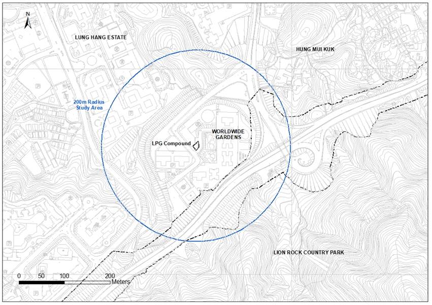
Plate 11.1 Location
of the LPG Compound
Objectives
11.2.1 The
Hazard to Life Assessment requirements for the LPG storage installations as
detailed in Appendix G of the EIA Study Brief are shown below:
(a)
Identify
hazardous scenarios associated with the on-site transport, storage and use of
gas as defined in the Gas Safety Ordinance (Cap. 51) at the LPG Storage
Installation and then determine a set of relevant scenarios to be included in a
Quantitative Risk Assessment (QRA);
(b)
Execute
a QRA of the set of hazardous scenarios determined in (a), expressing
population risks in both individual and societal terms;
(c)
Compare
individual and societal risks with the criteria for evaluating hazard to life
as stipulated in Annex 4 of the TM; and
(d)
Identify
and assess practicable and cost-effective risk mitigation measures.
EIAO TM Risk Criteria
11.2.2 Annex
4 of the EIAO-TM specifies the Individual and Societal Risk Guidelines. The
Hong Kong Risk Guidelines (HKRG) per the EIAO-TM Annex 4 states that the
individual risk is the predicted increase in the chance of fatality per year to
an individual due to a potential hazard. The individual risk guidelines require
that the maximum level of individual risk should not exceed 1 in 100,000 per
year i.e. 1×10⁻⁵ per year. Societal risk expresses the risks to the
whole population. It is expressed in terms of lines plotting the cumulative
frequency (F) of N or more deaths in the population from incidents at the
installation. Two F-N risk lines are used in the HKRG that demark “Acceptable”
or “Unacceptable” societal risks. To avoid major disasters, there is a vertical
cut-off line at the 1000 fatality level extending down to a frequency of 1 in a
billion years. The intermediate region indicates the acceptability of societal
risk is borderline and should be reduced to a level which is “as low as
reasonably practicable” (ALARP). It seeks to ensure that all practicable and
cost-effective measures that can reduce risk are considered. The HKRG is
presented graphically in Plate 11.2.
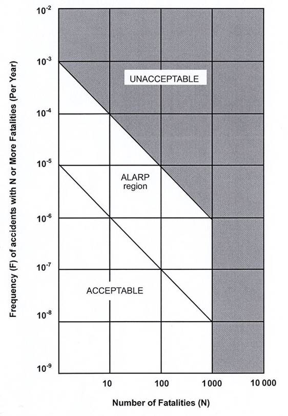
Plate 11.2 Societal
Risk Guidelines
11.3.1 This
assessment consists of the following six main tasks:
(a)
Data
/ Information Collection and Update: collect relevant data
/ information that is essential for the hazard assessment;
(b)
Hazard
Identification: identify credible set of hazardous scenarios associated
with the operation of the LPG Compound;
(c)
Frequency
Estimation:
estimate the frequencies of each hazardous event leading to fatalities based on
the collected data and operation data for LPG Compound with the support of
justifications from reviewing historical accident data and previous hazard
assessments;
(d)
Consequence
Analysis:
analyze the consequences of the identified hazardous scenarios;
(e)
Risk
Assessment and Evaluation: evaluate the risks associated with the
identified hazardous scenarios. The evaluated risks will be compared with HKRG
to determine their acceptability. Where necessary, risk mitigation measures
will be identified and assessed to comply with the “as low as reasonably
practicable” (ALARP) principle used in the HKRG; and
(f)
Identification
of Mitigation Measures: review the recommended risk mitigation
measures from previous studies. Practicable and cost-effective risk mitigation
measures will be identified and assessed as necessary. The risk outcomes of
the mitigated case will then be reassessed to determine the level of risk
reduction.
11.3.2 The
hazard assessment covers three scenarios:
·
Year
2033 without Project (Base case) – The risk imposed by the LPG Compound to the
planned population in 2033, in the absence of the Project.
·
Year
2033 with Project (Construction phase) – The risk imposed by the LPG Compound
to the planned population in 2033. This also accounts for the presence of the construction
workers operating in close vicinity of the LPG Compound and any potential
impacts associated with the construction activities.
·
Year
2041 (Operation phase) – The risk imposed by the LPG Compound to the planned
population in 2041 upon completion of the Project.
Study Area
11.4.1 The
LPG Compound is located at the southern direction of the commercial complex of
the Worldwide Gardens, which is currently occupied by the Anfield School. The
study area of 200m radius from the LPG compound was adopted in the study, as
shown in Plate 11.1.
11.4.2 Based
on information from survey maps and observations during the course of site
visit in May 2020, the LPG Compound is surrounded by Lung Pak Road, the Anfield
School and residential buildings. There is a 2m high cut slope located on the
north-west boundary of the LPG Compound.
Description of the LPG
Compound
LPG Storage
11.4.3 DSG
Energy Limited (DSG) is the operator of the LPG Compound which supplies LPG to
the local residents of Worldwide Gardens. According to the information
provided by DSG, the LPG Compound consists of two 2.4 tonnes (water capacity of
4.3 kL each) underground storage vessels, which are filled to a maximum
permissible level (85% of the maximum capacity) and equipped with two
vaporizers onsite. Furthermore, the two storage vessels were manufactured in
1998 and 2011 and were neither stress relieved nor radiographed.
LPG Delivery
and Transfer
11.4.4 LPG
is delivered to the LPG Compound by road tankers. The maximum capacity of the
road tanker is about 9 tonnes. Based on the information provided by DSG, there
are approximately 40 annual LPG deliveries and about 2 tonnes of LPG is being
transferred to the LPG Compound per delivery. The average resident time of the
LPG road tanker at the LPG Compound is around 45 minutes, which includes the
preparation time for facilitating the unloading operation.
11.4.5 Owing
to the site constraint, dedicated road tanker parking area is unavailable
within the LPG Compound and the LPG road tankers have to be parked at the
predefined area on the roadside next to the entrance of the LPG Compound during
unloading operation. This practice was adopted since its operation in the
1970s. As advised by DSG, precautionary measures specified for the concerned
LPG Compound are provided to minimize the potential risks due to this unloading
arrangement.
Population
11.4.6 Societal
risk is a measure of the consequence magnitude and the frequency of the
hazardous events. To establish the impact of any release (expressed as the
number of people likely to be affected), it is necessary to have a good
knowledge of the future population levels around the LPG Compound. This includes
residential population, institutional / commercial population and transport
population. However, the road tanker operators at the LPG Compound are
considered to be voluntary takers of risk and thus, excluded from the assessment.
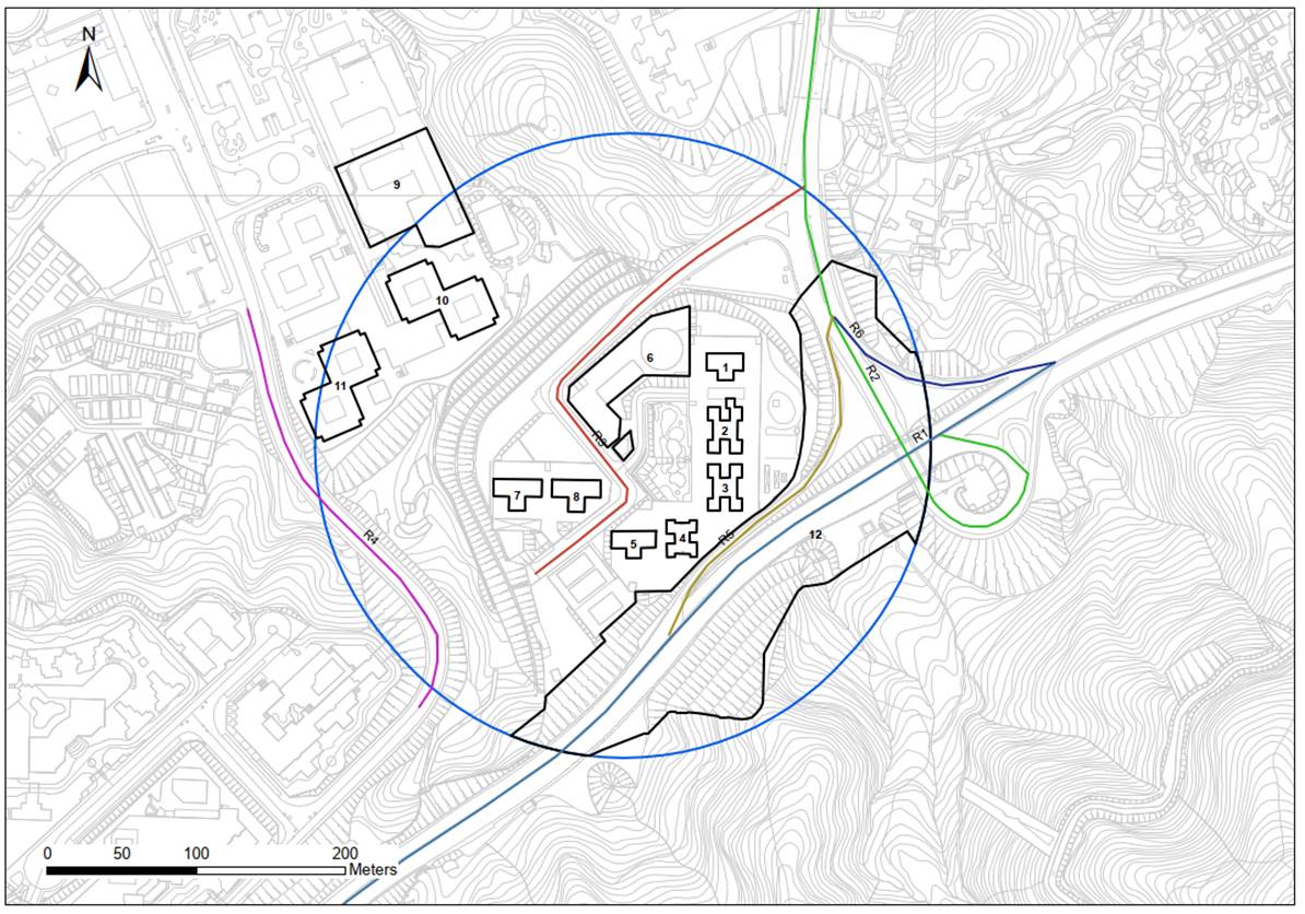
11.4.7 The
location of population groups and roads covered in the assessment is presented
in Plate 11.3, while photos of the surrounding population, as taken on
26th January 2021, are provided in Appendix 11.1. Additionally,
details on the estimated population for each population group are provided in Appendix 11.2.
Proposed Road Works for
the Project
11.4.8 Based
on the tentative construction programme of the Project, construction activities
on the portion of LRT Road and Hung Mui Kuk Road that fall within the 200 m
radius from the LPG Compound will be undertaken between Q4 of 2028 to Q2 of 2033.
These include:
·
Site
clearance
·
Slope
formation works
·
Noise
barrier & pipe pile wall/ L-shape retaining wall installation
·
Roadworks,
drainage, utilities, water mains
·
Landscape
works for slope
11.4.9 The
number of construction workers is estimated according to the Consultant’s
experience/ analysis based on projects of similar nature. It is assumed that
there will be 186 construction workers involved in the nearby construction
activities. This estimate represents the maximum number of nearby construction
workers envisaged during the peak construction period. The actual number of construction
workers engaged in the road widening works along the portion of Lion Rock
Tunnel Road and Hung Mui Kuk Road located within 200m radius study area is
expected to be smaller. Nonetheless, this estimate is applied as a
conservative approach.
Land and Building
Population
11.4.10 Hong Kong conducts
a population census once every ten years and a by-census in the middle of the
intercensal period. The Census data on the number of floors and units of the
residential developments, together with the Territory Population and Employment
Data Matrix (TPEDM) data on average household size, were used to estimate the
existing population of these developments.
11.4.11 The TPEDM
population projections for different Planning Data Zones (PDZ) were obtained
from the Planning Department (PlanD) to forecast the population for the
assessment years.
11.4.12 The
2016-based TPEDM data showed a negative growth of average domestic household
size in the PDZ 209 from 2016 to 2041. To be conservative, the residential
population in the future assessment years are assumed to remain the same as
those in Year 2016.
11.4.13 The
population in each area are listed in Table 11.1 and details on the
estimated population for each population group at different time modes and provided
in Appendix 11.2.
It is estimated with the following assumptions:
(a)
According
to 2016-based TPEDM data, a negative growth rate of -0.27% is observed for the
average domestic household size in Sha Tin District (i.e. PDZ 209) from 2016 to
2041, which decreases from 3.26 to 3.05. To be conservative, the average
domestic household size in the future assessment years are assumed to remain
the same as those in Year 2016 (i.e. 3.26).
(b)
For
Pok Oi Hospital Chan Kai Memorial College, the number of students was estimated
based on the maximum capacity per classroom (i.e. max. capacity of 45 students
for 26 classrooms), while the
number of staff recorded as of year 2020 is 56.
(c)
For
Anfield School, the number of students was estimated based on the maximum
capacity per classroom (i.e. max. capacity of 25 students for 12 classrooms and
max. capacity of 15 for 1 classrooms), while the
number of staff is estimated as 47.
(d)
School
populations was estimated based on the maximum student intake per class.
Furthermore, it is anticipated that majority of students attending Anfield
School and Pok Oi Hospital Chan Kai
Memorial College reside within Sha Tin District. According to
2016-based TPEDM data, a negative growth rate for residential population is
generally observed for PDZ 209 and the surrounding populations (i.e. PDZ 205,
206, 208, 210, 211, 384 and 385). As such, the changes in school populations
is expected to be minimal.
Occupancies
of different population groups at different time modes are summarised in Table 11.5. In
general,
(e)
The
weekday and weekend night-time population are assumed to be 100% of the maximum
residential population.
(f)
The
weekday and weekend daytime population are assumed to be 50% and 70% of the
residential population, respectively.
(g)
The
weekday daytime population is assumed to be 100% of the maximum school population.
(h)
An
average of 5% outdoor populations is considered for both residential and school
population group.
(i)
For
the proposed Project works area, the weekday and weekend daytime population are
assumed to be 100% and 50%, respectively and 100% outdoor population is
considered.
Table 11.1 Land and
Building Population Data
|
ID
|
Description
|
Population
|
|
|
Year 2033 – Base Case
[Note 1, 2]
|
Year 2033 – Construction Phase
|
Year 2041 – Operation Phase
|
|
|
1
|
Pine Court, Worldwide
Gardens
|
98
|
98
|
98
|
|
|
2
|
Hibiscus Court,
Worldwide Gardens
|
261
|
261
|
261
|
|
|
3
|
Lily Court, Worldwide
Gardens
|
261
|
261
|
261
|
|
|
4
|
Laurel Court,
Worldwide Gardens
|
274
|
274
|
274
|
|
|
5
|
Bauhinia Court, Worldwide
Gardens
|
137
|
137
|
137
|
|
|
6
|
Anfield School
|
362
|
362
|
362
|
|
|
7
|
Begonia Court,
Worldwide Gardens
|
150
|
150
|
150
|
|
|
8
|
Cypress Court,
Worldwide Gardens
|
150
|
150
|
150
|
|
|
9
|
Pok Oi
Hospital Chan Kai Memorial College
|
1226
|
1226
|
1226
|
|
|
10
|
Sheung
Sum House, Lung Hang Estate
|
|
10a
|
Low Block
|
1109
|
1109
|
1109
|
|
|
10b
|
High
Block
|
1275
|
1275
|
1275
|
|
|
11
|
Wai Sum
House, Lung Hang Estate
|
|
11a
|
Low Block
|
1109
|
1109
|
1109
|
|
|
11b
|
High
Block
|
1275
|
1275
|
1275
|
|
|
12
|
Proposed
Project Works Area [Note 3]
|
0
|
186
|
0
|
|
Note
1: Populations for residential were estimated based on domestic household
size in 2016-based TPEDM.
Note
2: School population for Pok Oi Hospital Chan Kai Memorial College and
Anfield School was estimated based on the school information from the Education
Bureau and school website.
Note 3: It
was assumed that there will be a maximum of 186 construction workers in the
nearby construction activities during the construction phase.
Road Population
11.4.14 The traffic
population considered in this assessment included the population travelling in
motor vehicles on Lion Rock Tunnel Road, Hung Mui Kuk Road, Chung Pak Road
& Lung Pak Street, Fu Kin Street and slip roads (i.e. LRT Road to Hung Mui
Kuk Road and Hung Mui Kuk Road to LRT Road). Speed limit on Lion Rock Tunnel
Road was assumed to be 80km/hr and 50km/hr was considered for the remaining
roads/ streets. The traffic population is predicted based on the following
equation:

11.4.15 Based on
the latest Annual Traffic Census (ATC) [2], the occupancies for each vehicle
type and vehicle mix were taken as the average at the core station no. 5024 (Lion
Rock Tunnel) which are considered representative of the road traffic in the
study area.
11.4.16 The traffic
population was assumed to be 100% outdoor. The estimated road population in
Year 2033 and Year 2041 are presented in Table
11.2 and Table 11.3, respectively and the detailed calculations are
provided in Appendix 11.2.
Table 11.2 Estimated
Road Population (Year 2033)
|
Population
ID
|
Description
|
Maximum Population [Note 1]
|
|
Daytime
|
Night-time
|
|
R1
|
Lion
Rock Tunnel Road
|
895
|
431
|
|
R2
|
Hung Mui
Kuk Road
|
711
|
341
|
|
R3
|
Chung
Pak Road & Lung Pak Street
|
10
|
8
|
|
R4
|
Fu Kin
Street
|
11
|
9
|
|
R5
|
Slip
road (Lion Rock Tunnel Road to Hung Mui Kuk Road)
|
20
|
15
|
|
R6
|
Slip
road (Hung Mui Kuk Road to Lion Rock Tunnel Road)
|
8
|
8
|
Note 1: Road
population was estimated based on Traffic Impact Assessment forecasted for Year
2034. This was conservatively applied for the assessed scenarios (i.e. Year 2033
– Base Case and Year 2033 – Construction Phase).
Table 11.3 Estimated
Road Population (Year 2041)
|
Population
ID
|
Description
|
Maximum Population [Note 1]
|
|
Daytime
|
Night-time
|
|
R1
|
Lion
Rock Tunnel Road
|
901
|
432
|
|
R2
|
Hung Mui
Kuk Road
|
711
|
341
|
|
R3
|
Chung
Pak Road & Lung Pak Street
|
10
|
8
|
|
R4
|
Fu Kin
Street
|
11
|
9
|
|
R5
|
Slip
road (Lion Rock Tunnel Road to Hung Mui Kuk Road)
|
20
|
15
|
|
R6
|
Slip
road (Hung Mui Kuk Road to Lion Rock Tunnel Road)
|
8
|
8
|
Note 1: Road
population was estimated based on Traffic Impact Assessment forecasted for Year
2041 and this was applied for Year 2041 – Operation Phase.
Time Modes
and Occupancies of Population Groups
11.4.17 Four
representative time modes were identified to address the variations in levels
of activities that could lead to a release and the variation in population in
the study area with time. Table 11.4 shows the time periods used in the
study. Furthermore, the assumptions of the occupancy rate for these specified
time modes including the indoor ratio considered for various population groups
are summarized in Table 11.5.
Table 11.4 Definitions
of Time Modes
|
Time
Period
|
Definition
|
Proportion of Time
|
|
Weekday
Day
|
Mon-Fri,
7am-7pm
|
35.71%
|
|
Weekday Night
|
Mon-Fri, 7pm – 7am
|
35.71%
|
|
Weekend Day
|
Sat-Sun, 7am-7pm
|
14.29%
|
|
Weekend Night
|
Sat-Sun, 7pm – 7am
|
14.29%
|
Table 11.5 Occupancies
of Population Groups at Different Time Modes
|
Population
Group
|
Percentage of Occupancy at Different Time Modes
|
Indoor Ratio
|
|
Weekday (Day)
|
Weekday
(Night)
|
Weekend (Day)
|
Weekend
(Night)
|
|
Residential
|
50%
|
100%
|
70%
|
100%
|
95%
|
|
School
|
100%
|
0%
|
0%
|
0%
|
95%
|
|
Proposed
Project Works Area
|
100%
|
0%
|
50%
|
0%
|
0%
|
|
Lion Rock
Tunnel Road/ Hung Mui Kuk Road
|
100%
|
50%
|
100%
|
50%
|
0%
|
|
Chung Pak
Road & Lung Pak Street/ Fu Kin Street/ Slip road (Lion Rock Tunnel Road
to Hung Mui Kuk Road)
|
100%
|
80%
|
100%
|
80%
|
0%
|
|
Slip road
(Hung Mui Kuk Road to Lion Rock Tunnel Road)
|
100%
|
100%
|
100%
|
100%
|
0%
|
11.5.1 Meteorological
data is required for consequence modelling and risk calculation. Consequence
modelling (dispersion modelling) requires wind speed and stability class to
determine the degree of turbulent mixing potential whereas risk calculation
requires wind-rose frequencies for each combination of wind speed and stability
class.
11.5.2 Meteorological
data was obtained from Sha Tin Weather Station (2019) where wind speed,
stability class, weather class and wind direction are available. This data
represents the weather conditions for the whole year in 2019 and has already
taken into account of seasonal variations and is therefore considered
applicable for the assessment. Table 11.6 shows the wind
speed-stability frequencies.
Table 11.6 Stability
Category-Wind Speed Frequencies at Sha Tin Station
|
Daytime
|
|
Wind
Speed (m/s)
|
A
|
B
|
C
|
D
|
E
|
F
|
Total
(%)
|
|
0.0-1.9
|
10.41
|
6.96
|
0.00
|
9.47
|
0.00
|
11.99
|
38.83
|
|
2.0-3.9
|
7.69
|
18.85
|
8.33
|
9.84
|
4.38
|
0.73
|
49.82
|
|
4.0-5.9
|
0.00
|
4.75
|
3.38
|
2.31
|
0.11
|
0.00
|
10.55
|
|
6.0-7.9
|
0.00
|
0.00
|
0.21
|
0.57
|
0.00
|
0.00
|
0.78
|
|
Over 8.0
|
0.00
|
0.00
|
0.02
|
0.00
|
0.00
|
0.00
|
0.02
|
|
All (%)
|
18.10
|
30.56
|
11.94
|
22.19
|
4.49
|
12.72
|
100.00
|
|
Night-time
|
|
Wind
Speed (m/s)
|
A
|
B
|
C
|
D
|
E
|
F
|
Total
(%)
|
|
0.0-1.9
|
0.00
|
0.00
|
0.00
|
2.24
|
0.00
|
63.72
|
65.96
|
|
2.0-3.9
|
0.00
|
0.00
|
0.00
|
8.84
|
17.21
|
3.26
|
29.31
|
|
4.0-5.9
|
0.00
|
0.00
|
0.00
|
4.25
|
0.34
|
0.00
|
4.59
|
|
6.0-7.9
|
0.00
|
0.00
|
0.00
|
0.14
|
0.00
|
0.00
|
0.14
|
|
Over 8.0
|
0.00
|
0.00
|
0.00
|
0.00
|
0.00
|
0.00
|
0.00
|
|
All (%)
|
0.00
|
0.00
|
0.00
|
15.47
|
17.55
|
66.98
|
100.00
|
11.5.3 According
to Table 11.6, 6 combinations (2B, 1D, 3D, 6D, 2E and 1F)
and 5 combinations (1D, 4D, 6D, 2E and 1F)
of wind speed and stability class were chosen for daytime and night-time
meteorological conditions, respectively. These combinations are considered
adequate to reflect the full range of observed variations in these quantities. It
is not necessary and efficient to consider every combination observed. The
principle is to group these combinations into representative weather classes that
together cover all conditions observed.
11.5.4 Once
the weather classes have been selected, frequencies for each wind direction for
each weather class can then be determined. The frequency distributions for the
daytime and night-time meteorological conditions are summarized in Table 11.7.
Table 11.7 Weather
Class-Wind Direction Frequencies at Sha Tin Station
|
Daytime
|
|
Direction
|
2B
|
1D
|
3D
|
6D
|
2E
|
1F
|
Total (%)
|
|
0 – 30
|
5.21
|
1.05
|
2.52
|
0.00
|
1.78
|
1.21
|
11.77
|
|
30 – 60
|
13.45
|
1.05
|
4.47
|
0.05
|
1.28
|
1.07
|
21.37
|
|
60 – 90
|
5.66
|
1.31
|
3.14
|
0.12
|
1.05
|
1.69
|
12.97
|
|
90 – 120
|
6.70
|
1.02
|
4.11
|
0.00
|
1.59
|
1.31
|
14.73
|
|
120 – 150
|
5.23
|
0.40
|
2.81
|
0.02
|
0.86
|
0.38
|
9.70
|
|
150 – 180
|
1.12
|
0.14
|
0.67
|
0.00
|
0.17
|
0.21
|
2.31
|
|
180 – 210
|
1.26
|
0.24
|
0.78
|
0.00
|
0.31
|
0.52
|
3.11
|
|
210 – 240
|
7.42
|
0.29
|
6.51
|
1.50
|
0.78
|
0.43
|
16.93
|
|
240 – 270
|
2.54
|
0.24
|
1.66
|
0.19
|
0.38
|
0.21
|
5.22
|
|
270 – 300
|
0.26
|
0.10
|
0.07
|
0.00
|
0.00
|
0.10
|
0.53
|
|
300 – 330
|
0.02
|
0.05
|
0.00
|
0.00
|
0.00
|
0.24
|
0.31
|
|
330 – 360
|
0.45
|
0.19
|
0.07
|
0.00
|
0.05
|
0.29
|
1.05
|
|
All (%)
|
49.32
|
6.08
|
26.81
|
1.88
|
8.25
|
7.66
|
100.00
|
|
Night-time
|
|
Direction
|
1D
|
4D
|
6D
|
2E
|
1F
|
Total
(%)
|
|
0 – 30
|
0.50
|
1.09
|
0.00
|
5.04
|
6.22
|
12.85
|
|
30 – 60
|
0.30
|
1.86
|
0.02
|
5.59
|
6.10
|
13.87
|
|
60 – 90
|
0.17
|
1.99
|
0.02
|
5.14
|
8.86
|
16.18
|
|
90 – 120
|
0.15
|
1.34
|
0.00
|
5.84
|
6.12
|
13.45
|
|
120 – 150
|
0.10
|
0.82
|
0.00
|
3.06
|
4.80
|
8.78
|
|
150 – 180
|
0.00
|
0.30
|
0.05
|
0.84
|
3.80
|
4.99
|
|
180 – 210
|
0.02
|
0.12
|
0.00
|
0.92
|
3.31
|
4.37
|
|
210 – 240
|
0.00
|
4.90
|
0.22
|
5.34
|
2.29
|
12.75
|
|
240 – 270
|
0.05
|
2.16
|
0.02
|
2.34
|
1.64
|
6.21
|
|
270 – 300
|
0.05
|
0.00
|
0.00
|
0.15
|
1.69
|
1.89
|
|
300 – 330
|
0.07
|
0.00
|
0.00
|
0.02
|
1.37
|
1.46
|
|
330 – 360
|
0.17
|
0.00
|
0.00
|
0.32
|
2.71
|
3.20
|
|
All (%)
|
1.58
|
14.58
|
0.33
|
34.60
|
48.91
|
100.00
|
Introduction
11.6.1 A
hazard is described as the property of a material or activity with the
potential to do harm. A release of flammable gas such as LPG has the potential
to cause fire or explosion if ignited. Without ignition, the gas vapour will
disperse harmlessly. Under normal conditions, the LPG at the existing LPG
Compound will be stored and handled under contained and controlled manners. For
LPG to pose a hazard to the people in the surrounding area, a release must
occur as a result of a failure of that containment or as a result of faulty
transfer procedures.
11.6.2 This
section of the report summarizes all possible failure cases and associated
failure rates that could lead to a release of LPG. The failure rates adopted
throughout this report are quoted in the paper on “Quantitative Risk Assessment
Methodology for LPG Installations (Reeves, Minah and Chow, 1997)” [4]. Furthermore,
reference for certain frequencies are drawn from approved EIA Reports [5][6]
and QRA studies [7][8] where necessary and appropriate. In addition, possible
initiating events are identified.
Behaviour of LPG Releases
11.6.3 LPG
is a mixture of butane and propane. The gas is twice as heavy as air. For a
release of LPG, the nature of the combustion will depend on the timing of
ignition and the size of the release.
11.6.4 A
release of several tonnes of LPG, if ignited immediately, will produce a
fireball. Initially, the gas concentration in the mixture will be above the
Upper Flammability Limit (UFL). As burning occurs around the edges of the
release, this will entrain more air into the mixture and more combustion will
take place. The process accelerates until the mixture rising above the ground
as a ball of fire. A fireball may also result from a boiling liquid expanding
vapour explosion (BLEVE). This results from the bursting of a vessel (owing to
a high internal pressure and a weakening of the vessel material, as a result of
a fire for example). The vessel contents rapidly vaporize and are ignited.
11.6.5 If
not ignited immediately, the gas will disperse and dilute. If ignition occurs
when the gas concentration is between the lower Flammability Limit (LFL) and the
Upper Flammability Limit (UFL), a flame front will propagate to produce a flash
fire.
11.6.6 For
small releases, immediate ignition will produce a long vigorous jet flame from
the point of release. As for large releases, delayed ignition will generally
produce a flash fire.
11.6.7 For
all sizes of release, the LPG will disperse harmlessly if there is no source of
ignition.
Hazard
Analysis
Spontaneous Failures
Failure of Storage Vessel
11.6.8 Failure
of a vessel can be resulted from (i) a cold catastrophic failure leading to
instantaneous release of the full inventory and (ii) a partial failure leading
to continuous release of the full inventory via a 25mm hole. The causes of
failure are summarized as follows:
(a)
Spontaneous
failure due to corrosion, fatigue, etc.
(b)
Overfilling
(c)
Earthquake
Failure of Road Tanker
Guillotine Failure of Liquid
Filling Line to Storage Vessel
11.6.10 Failure of the
liquid line is possible as a result of corrosion or fatigue, vehicle impact and
external events. Only guillotine failure of the LPG pipework is considered in
this study as partial failure of pipework is deemed as an insignificant
contributor towards the overall risk levels. The failure would result in LPG
leaking from the full bore of the pipe. Moreover, part of the pipework is
installed aboveground. Failure of the aboveground portion of the liquid
filling line can result from vehicle impact while failure of the underground
portion of the liquid filling line can result from earthquake.
Guillotine Failure of Liquid
Supply Line to Vaporizers
11.6.11 The liquid
supply line connects the underground storage vessel and vaporizers. Failure of
the liquid line is possible as a result of corrosion or fatigue, vehicle impact
and external events. Only guillotine failure of the LPG pipework is considered
in this study as partial failure of pipework is an insignificant contributor to
the overall risk levels. The failure would result in LPG leaking from the full
bore of the pipe. Since the pipework is protected by fencing, vehicle impact is
not considered credible. However, failure of the liquid line can result from
earthquakes.
Failure of Vaporizers
11.6.12 Two units
of vaporizers are installed at the LPG Compound. Each vaporizer can convert
LPG to gaseous fuel at the maximum capacity of 0.15 tonnes / hour. Apart from
spontaneous failure and loading failure, failure of the vaporizers can result
from earthquakes and aircraft crashes.
Guillotine Failure of Liquid
Line from Tanker Pipe to Loading Hose
11.6.13 The cause
of failure of this line is similar to that of the liquid filling line to the storage
vessel, namely mainly corrosion or fatigue. Moreover, the failure can be due
to vehicle impact and other external events.
Failure of Flexible Hose
11.6.14 The loading
hose could fail due to the following causes:
(a)
Fatigue
(b)
Hose
misconnection
(c)
Hose
disconnection during loading or unloading process
(d)
Operator
/ driver error
Loading / Unloading Failures
11.6.15 When LPG
releases occur as a direct result of the road tanker unloading operation, the
failure events can be regarded as loading failures. The failure events that
were considered in the study include:
(a)
Hose
misconnection and disconnection error
(b)
Tanker
drive away error
(c)
Road
tanker collision
(d)
Vehicle
impact with road tanker during unloading
(e)
Storage
vessel overfilling
(f)
Over-pressurization
of pipework.
Hose Misconnection and
Disconnection Error
11.6.16 A
significant release of LPG during its transfer from road tanker to storage
vessel could occur as a result of the failure of the transfer hoses and
coupling, human error, or vehicle impact.
Tanker Drive away Error
11.6.17 This error
could result from: (i) repositioning of the road tanker during delivery; and/or
(ii) the driver driving the road tanker away before the delivery is completed. Since
the LPG road tankers are to be parked uphill during the unloading operation,
wheel-stoppers will be applied as an additional precautionary measure to
prevent the road tankers from rolling backwards in case the conventional
parking brake malfunctions.
Road Tanker Collision
11.6.18 Road tanker
collision refers to an event in which an LPG road tanker strikes the facilities
of the LPG Compound and causes damages to these facilities. There is no
dedicated road tanker parking area and unloading area within the LPG Compound
due to the site constraint and the LPG road tanker parked outside the LPG
Compound during the LPG unloading operation. However, speed control and
well-adopted training system are safety measures commonly adopted to avoid
serious collision incidents. The probability of minor impact of the road tanker
with sufficient energy to cause damage of its vessel (either rupture or
leakage) mounted on the tanker is considered to be insignificant. The LPG
facilities such as LPG storage vessels, vaporizers and pipework would not be
affected by this event since they are installed within the LPG Compound.
Vehicle Impact with Road
Tanker during Unloading
11.6.19 Dedicated
road tanker parking area and unloading area is unavailable within the LPG
Compound and the LPG road tankers park on the public road outside the LPG
Compound. Safety precaution measures including safety cones and warning signs
will be provided to warn other road users during unloading operation. Although
the driver / assistant will monitor the road condition and signal will be
provided on the road during the LPG unloading operation, there is a possibility
that a vehicle collides with the road tanker during unloading operation leading
to LPG release.
Storage Vessel Overfilling
11.6.20 Failure of the
LPG storage vessel could occur as a result of overfilling of LPG from the road
tanker to the vessel.
Over-pressurization of
Pipework
11.6.21 Over-pressurization
could be caused by continuing unloading operation when a storage vessel is
overfilled or the isolation valves at the receiving storage vessel are closed.
External Events
11.6.22 A LPG release
event could occur as a result of external events and the consequences could be
catastrophic. The related external events are listed as follows:
(a)
Earthquake
(b)
Aircraft
crash
(c)
Landslide
(d)
Severe
environmental event such as typhoon or tsunami and subsequent outcomes such as
falling trees
(e)
Subsidence
(f)
Lightning
(g)
High
wind loading
Earthquake
11.6.23 According
to Reeves et al. (1997) [4], an earthquake of Modified Mercalli Intensity (MMI)
VIII could provide enough intensity to result in damage to the storage vessel
or pipework. Therefore, earthquake was considered in this study.
Aircraft Crash
11.6.24 Aircrafts
crashing into the LPG Compound due to take-off and landing as well as arrival/
departure flight paths were accounted for in this study. The method given in
HSE (1997) [10] for the calculation of aircraft crash frequency was adopted.
Landslide
11.6.25 The LPG
Compound is not situated near any natural terrain, there is a 2m high cut slope
located on the north-west boundary of the LPG Compound. The cut slope has been
protected with 100% shotcrete that landslide is not anticipated. Therefore,
this external event was not further considered in this study.
Severe environmental event
11.6.26 According to
BDEIA [5], loss of LPG content owing to severe environmental events such as
typhoon or tsunami (i.e. a tidal wave following an earthquake) was considered
to be insignificant as the installation of LPG vessels is situated underground
and away from the seashore. The Super Typhoon Mangkhut is one of the strongest
storms attacking Hong Kong in recent years. It struck the Pearl River Estuary
on 16 September 2018 and resulted in severe disasters in Hong Kong. Heavy
rain, storm surge and high waves caused serious flooding in many coastal and
low-lying areas and there were more than 60,000 reports of fallen trees, the
highest number on record [9]. There is a tree sitting on the northern
boundary of the LPG Compound, separated by a 2m boundary fence. Further, the
LPG vessels are located underground and the vaporizers are sheltered inside a
concrete structure, the probability of fallen trees damaging the LPG facilities
in the LPG Compound was considered to be minimal.
Subsidence
11.6.27 Subsidence
is usually slow in movement and such movement can be observed and remedial
action can be taken in time. Therefore, the probabilities of severe
environmental events and subsidence are very small or negligible and such
external events were not further considered in this study.
Lightning and High wind
loading
11.6.28 The LPG
Compound is surrounded by tall buildings that shield the LPG Compound from
damage by high winds. Also, lightning is more likely to strike the tall
structures. Frequency of high winds damaging the LPG Compound and lightning
strike on the LPG Compound was assumed to be less than the credible frequency
of 1×10⁻⁹ per year. A LPG release due to high wind and lightning was
therefore not further assessed in this study.
Safety Features
11.6.29 Safety
features installed in the facilities of the LPG Compound can act in different
combination to mitigate LPG releases. The safety features considered in this
study are listed as follows:
(a)
Non-return
valve
(b)
Excess
flow valve
(c)
Emergency
shutdown system
(d)
Breakaway
coupling
(e)
Manual
isolation system
(f)
Double-check
filler valve
(g)
Relief
valve
Non-return Valve
11.6.30 Non-return
valve on the liquid filling line can isolate release immediately. If it
functions properly, there will be no significant consequence.
Excess Flow Valve
11.6.31 Excess flow
valve installed at the road tanker and the storage vessel is expected to
mitigate a release from guillotine failure of the pipework or the flexible
filling hose.
Emergency Shutdown System
11.6.32 An
Emergency Shutdown (ESD) system is installed on both the road tankers and the
storage vessels. For a release from a road tanker, the emergency isolation
system and engine emergency stop system can be activated to isolate the release
due to equipment failure and human error. For a release from the vessels, the emergency
isolation system can be triggered to prevent a release on the filling line or downstream
of the hose connection.
Breakaway Coupling
11.6.33 There is a
possibility of road tankers being driven away whilst the hose is still
connected, thereby causing damage to the facilities of the LPG Compound and
resulting in the release of LPG. The breakaway coupling is installed to
prevent undue spillage of LPG owing to the movement of road tankers.
Manual Isolation System
11.6.34 A manual
valve is installed for the operators / drivers to shut off the delivery
connection manually in case of failure.
Double-check Filler Valve
11.6.35 Double-check
filler valve is provided at the hose connection point on the liquid filling
line to prevent release to be fed back from the vessel. The design of this
valve is essentially 2 non-return valves in series.
Relief Valve
11.6.36 Relief
valve is employed to ensure that the vessel is not subjected to an excessive
internal pressure that may cause a failure as a result of overfilling. It also offers
protection against excessive pressure build-up within the vessel in case of
fire.
Human Error
11.6.37 When a failure
of equipment or loading process occurs, it is possible for the operator to
rectify the problem before a hazard event occurs. Human error is regarded as a
failure case if the operator fails to rectify the problem.
Fire Protection / Fighting System
Chartek Coating
11.6.38 Chartek
coating is a safety feature of all road tankers. The coating has been reported
to provide protection for at least 30 minutes in the case of a jet fire. The
coating could prevent a hot spot from developing in a jet fire attack on the
road tanker, which can cause thermal weakening of the road tanker wall leading
to BLEVE.
Water Spray System
11.6.39 There is no
water spray system installed at the LPG Compound. No provision for fire
services installation for controlling road tanker fires or lowering the
temperature of fires to avoid BLEVE was applied.
Fire Service
11.6.40 The fire
services will be available within a few minutes in case of a fire. The extinction
of fire by fire fighters prevents BLEVE from occurring.
Escalation
11.6.41 BLEVE of a
LPG road tanker can happen if the road tanker is impinged by jet fire from the aboveground
LPG facilities listed below:
(a)
Cold
partial failure of road tanker
(b)
Guillotine
failure of liquid filling line to vessel
(c)
Guillotine
failure of liquid supply line to vaporizer
(d)
Flexible
hose during loading to storage vessel
(e)
Liquid
line from tanker to loading hose
(f)
Vaporizer
failure
Summary
11.6.42 The possible
hazard events for the day-to-day operation of the LPG Compound have been
identified and reviewed in previous section. Only those possible failure cases
considered to have the potential to cause off-site fatality are summarized in Table 11.8.
Table 11.8 Identified
Failure Case of the LPG Compound
|
Failure Types
|
Failure Cases
|
|
Spontaneous
Failure of Pressurized LPG Equipment
|
· Storage Vessel
Failure
· Road
Tanker Failure
· Pipework
Failure
· Hose
Failure
· Vaporizer
Failure
|
|
External
Event
|
· Earthquake
MMI VIII
· Aircraft
Crash
|
|
Delivery
Failure
|
· Hose
Misconnection Error
· Hose
Disconnection Error
· Tanker
Drive-away Error
· Road
Tanker Collision during Unloading
· Vehicle
Impact with Road Tanker during Unloading
· Storage
Vessel Overfilling
· Over-pressurization
of pipework
|
|
Safety
System Failure
|
· Pressure
Relief Valve Failure
· Non-return
Valve Failure
· Excess
Flow Valve Failure
· Emergency
Shutdown System Failure
· Double-check
Filler Valve Failure
· Breakaway
Coupling Failure
· Human
Error
· Manual
Isolation Valve Failure
|
|
Fire
Fighting System Failure
|
· Fire
Services Failure
· Chartek
Coating Failure
|
Introduction
11.7.1 Subsequent
to the Hazard Identification and Analysis, the next step is to estimate the
likelihoods of various LPG release scenarios. There are combinations of hazard
initiating events, as identified in previous section, which would lead to a LPG
release.
11.7.2 Fault
Tree Analysis (FTA) permits the hazardous incident (“Significant Failure
Events”) frequency to be estimated from a logical model of the failure
mechanisms of a system. The model is based on the combinations of failures of
more basic components, safety systems and human errors.
11.7.3 FTA
is the use of a combination of simple logic gates, “AND” and “OR” gates, to
synthesize a failure model of the hazardous installation. The “Significant
Failure Events” frequency is calculated from failure data of more simple
events.
11.7.4 A
basic assumption in FTA is that all failures in a system are binary in nature,
a component or operator either performs successfully or fails completely. In
addition, the system is assumed to be functioning if all sub-components are
operating properly.
11.7.5 The
stepwise procedure for undertaking FTA is presented below:
(a)
Hazard
identification and selection of the “Significant Failure Events”
(b)
Construction
of fault tree
(c)
Quantitative
evaluation of the fault tree
Frequency Estimation
Spontaneous Failure of Pressurized LPG Equipment
Storage Vessel Failure
11.7.6 A
release of LPG could occur as a result of catastrophic failure or partial
failure of the storage vessel and such a failure would lead to either a loss of
entire contents of the vessel or a continuous release of LPG to atmosphere.
11.7.7 Generic
failure rates of 1.8×10⁻⁷ per vessel year [4] and 5.0×10⁻⁶
per vessel year [4] were adopted for cold catastrophic failure and cold partial
failure, respectively.
11.7.8 The
service life of both storage vessels will exceed 20 years by 2018 and 2031
respectively. Considering the assessment year for base case is 2033, a corrosion
modification factor of 2 is applied to account for the age of vessels [4] for
all hazard scenarios.
Road Tanker Failure
11.7.9 As
discussed in Section 11.6.9, the definitions of catastrophic and partial
failures are similar to those of the storage vessel. It is generally
considered that catastrophic failure rate for LPG road tankers could be higher
than for a fixed storage vessel because of a) stresses experienced by the road
tanker due to vibration during transportation; and b) cyclic loading associated
with filling/unloading the road tanker.
11.7.10 Failure
rates of 2.0×10⁻⁶ per tanker year [4] and 5.0×10⁻⁶ per
tanker year [4] were adopted for catastrophic tanker failure and partial
failure of road tanker, respectively.
Pipework Failure
Vaporizer Failure
11.7.12 The effect
of partial failure of the vaporizer is ignored. A generic guillotine failure
rate of the vaporizer coil was taken to be 1.0×10⁻⁶ per meter per
year [4].
Hose Failure
External Events
Earthquake MMI VIII
11.7.14 The
probability of 1.0×10⁻⁵ per year was adopted for the occurrence of an
MMI VIII earthquake. The failure rate of pipework and partial failure of
underground vessel owing to earthquakes was assumed to be 0.01 [5], whereas the
probability of failure for road tanker was considered to be zero.
Aircraft Crash
11.7.15 The distance between the
nearest arrival flight path for the Hong Kong International Airport (HKIA) and
the LPG Compound is approximately 2.1km. The distance between the LPG
Compound and HKIA is about 26km, which exceeds the criteria of 5 miles (8 km)
for the consideration of airfield accident. At such distances, the LPG
Compound does not come into the flight paths of the critical takeoff and
landing phases, and therefore only the background crash rate and airway crash
rate were accounted for. The frequency of aircraft crash was estimated using
the methodology of the HSE (1997) [10]. The model took into account specific
factors such as the target area of the LPG Compound and the distance between
the LPG Compound and the runway threshold. The aircraft crash frequency per
year was calculated as:
Frequency (per year) = Background Crash Rate +
Airway Crash Rate
Frequency (per year) = (A x Bi )+ (A x Ni
x Ri x afac/ alt)
Where
A = Area of the LPG Compound (8.3×10⁻⁵ km2)
N = Number of aircraft movements per year
Bi = Background crash rate for aircraft (2×10⁻⁶
per year per km2 [10])
Ri = Aircraft in-flight reliability (4.7×10⁻¹¹
per year per km per aircraft movement [10])
afac = Area factor obtained from Table 9 of UK HSE
report [10]
Alt = Mean altitude of aircraft (5 km)
11.7.16 The area
factor (afac) is defined as the probability of a crash at a given location
relative to the airway. With reference to Table 9 of UK HSE report [10], afac
of 0.37 was adopted based on the corresponding x1 of 0.42, as estimated from
the below equation:
x1 = x/ alt
Where
x = Minimum horizontal distance from the nearest
flight path to the LPG Compound (2.1km)
Alt = Mean altitude of aircraft (5 km)
Loading / Unloading Failures
Hose Misconnection Error
11.7.18 A
significant release of LPG during its transfer from the road tanker to the storage
vessel could occur as a result of failure of the transfer hoses and coupling,
human error, or vehicle impact. The likelihood of such an event was taken as
3×10⁻⁵ per operation [4].
Hose Disconnection Error
11.7.19 A failure
rate of 2.0×10⁻⁶ per operation [4] was adopted for this failure case.
Tanker Drive-away Error
11.7.20 Tanker
drive-away error refers to an event in which the tanker moves away with the
hose still connected. It could result from the tanker driver inadvertent driving
the vehicle away before delivery is completed. It was considered that
drive-away is unlikely. Even if such error do occur, it is highly likely that
the failure can be immediately rectified since the delivery process would not
go unattended. A failure rate of 4.0×10⁻⁶ per operation [4] was adopted.
Tanker Collision during
Unloading
11.7.21 A release
of LPG cloud occurs as a result of an incident involving an LPG tanker and LPG
equipment during delivery. The failure rate of tanker impact during unloading was
assumed to be 1.5×10⁻⁴ per delivery [4].
Vehicle Impact with Road
Tanker during Unloading
11.7.22 A rate of
1×10⁻⁸ per operation [4] was adopted for the case that a vehicle
impact into road tanker during unloading.
Overfilling of Storage Vessel
11.7.23 The
practice on-site in unloading LPG to the storage vessel is that the vessel will
only be filled to 85% of its maximum capacity. It was considered that the
probability of the driver overfilling a storage vessel is low. A rate of
2.0×10⁻² per operation [4] was adopted for this failure case.
Over-pressurization of
Pipework
11.7.24 This event
has been taken into account by pipework and hose failure data in Sections 11.7.11 and 11.7.13. Hence, it was not considered separately in the
assessment.
Safety System Failure
11.7.25 If the
safety system operates as designed then releases would not present an off-site
hazard. There is, however, potential for failure of the safety system. The typical
safety systems involve pressure relief valve, non-return valve, excess flow
valve, emergency shutdown system, breakaway coupling and double-check filler
valve.
Pressure Relief Valve Failure
11.7.26 The pressure
relief valve avoids the LPG pipework or underground storage vessels from
getting overpressure. A generic failure of 1×10⁻⁴ [4] for the pressure
relief valve per demand was adopted.
Pump Overpressure Protection
System
11.7.27 Such system
is installed on LPG road tankers to control the maximum outlet pressure of the
pump. In addition to the internal pump overpressure by-pass, the pump or
adjacent pipework is fitted with a separate by-pass valve that set at a lower
differential pressure to automatically carry any excess liquid back to the road
tanker vessel when the delivery valve is closed.
11.7.28 A generic
failure of pump overpressure protection system of 1×10⁻⁴ per demand
[4] was adopted.
Non-return Valve Failure
11.7.29 The non-return
valve is intended to prevent back flow of LPG. A generic failure rate of 0.013
per demand [4] was adopted.
Excess Flow Valve Failure
11.7.30 The excess
flow valve installed at the road tanker and the storage vessel is expected to
be functional when guillotine failure of pipework or flexible hose occurs. A
generic failure rate of 0.13 per demand [4] was adopted for the line to
vaporizer.
Emergency Shutdown System
Failure
11.7.31 A generic
failure rate of 1.0×10⁻⁴ per demand [4] was assumed.
Breakaway Coupling Failure
11.7.32 A generic
failure rate of 0.013 per demand [4] was adopted for the road tanker.
Double-check Filler Valve
Failure
11.7.33 A
double-check filler valve prevents the LPG release to be fed back from the
storage vessel. The design has two non-return valves in series. A generic
failure rate of 2.6×10⁻³ per demand [4] for common mode failure was
adopted.
Manual Isolation Valve
11.7.34 Manual
valve is installed for operators / drivers’ intervention in case of failure.
11.7.35 A generic
failure rate of 0.5 per demand [4] was adopted.
Human error
11.7.36 A probability
of 1.5×10⁻³ per demand was assumed to account for the human error in
which the operators fail to rectify the problem before any hazard event occurs.
Fire Fighting System Failure
Water Spray System Failure
11.7.37 Water Spray
System is not installed on site.
Failure of Fire Services
11.7.38 It was assumed
that the Fire Services would always be available, and therefore zero
probability was applied for the failure of “fire services arrive late”. A
generic failure rate of 0.5 per demand [4] was assumed for the fire services to
be ineffective against a fire attack.
Chartek Coating Failure
11.7.39 A generic
failure rate of 0.1 per demand [4] was applied for Chartek coating fails to
prevent a hot spot from developing on the road tanker in a jet fire attack owing
to poor maintenance.
11.7.40 A summary
of the identified failure cases and their associated failure rates adopted are
presented in Table 11.9.
Table 11.9 Summary
of Identified Failure Cases and Their Associated Failure Rates
|
Failure Cases
|
Failure Rates
|
Reference Source
|
|
Spontaneous Failure of Pressurized LPG
Equipment
|
|
Catastrophic Failure
of Storage Vessel
|
1.8×10⁻⁷ per vessel year
|
Reference [4]
|
|
Partial Failure of Storage Vessel
|
5.0×10⁻⁶ per vessel year
|
Reference [4]
|
|
Catastrophic Failure of Road Tanker
|
2.0×10⁻⁶ per tanker year
|
Reference [4]
|
|
Partial Failure of Road Tanker
|
5.0×10⁻⁶ per tanker year
|
Reference [4]
|
|
Guillotine Failure of Pipework
|
1.0×10⁻⁶ per meter per year
|
Reference [4]
|
|
Vaporizer Failure
|
1.0×10⁻⁶ per meter per year
|
Reference [4]
|
|
Hose Failure
|
1.8×10⁻⁷ per transfer or
9.0×10⁻⁸ per hour
|
Reference [4]
|
|
External Event
|
|
Earthquake MMI VIII
|
1.0×10⁻⁵ per year
|
Reference [4]
|
|
Aircraft Crash
|
2.87×10⁻¹⁰ per year
|
Refer to Section 11.7.15 to 11.7.17
|
|
LPG Loading Failure
|
|
Hose Misconnection Failure
|
3.0×10⁻⁵ per operation
|
Reference [4]
|
|
Hose Disconnection Failure
|
2.0×10⁻⁶ per operation
|
Reference [4]
|
|
Tanker Drive-away Error
|
4.0×10⁻⁶ per operation
|
Reference [4]
|
|
Road Tanker Collision
|
1.5×10⁻⁴ per operation
|
Reference [4]
|
|
Vehicle Impact into Tanker During
Unloading
|
1.0×10⁻⁸ per operation
|
Reference [4]
|
|
Storage Vessel Overfilling
|
2.0×10⁻² per operation
|
Reference [4]
|
|
Safety Features Failure
|
|
Pressure Relief Valve Failure
|
1.0×10⁻⁴ per demand
|
Reference [4] based on ESD system
|
|
Failure of Pump Over-pressurization Protection
|
1.0×10⁻⁴ per demand
|
Based on pressure relief valve
|
|
Non-return Valve Failure
|
0.013 per demand
|
Reference [4]
|
|
Excess Flow Valve Failure
|
1.00 per demand for liquid filling line and flexible hose
0.13 per demand for line to vaporizer
|
Reference [4]
|
|
Manual Isolation Valve Failure
|
0.5 per demand
|
Reference [4]
|
|
Emergency Shutdown System Failure
|
1.0×10⁻⁴ per demand
|
Reference [4]
|
|
Breakaway Coupling Failure
|
0.013 per demand for tanker
|
Reference [4] Conservative estimate, based on breakaway
coupling for road tanker
|
|
Double-check Filler Valve Failure
|
2.6×10⁻³ per demand
|
Reference [4]
|
|
Operator fails to rectify problem
|
1.5×10⁻³ per demand
|
Reference [3]
|
|
Fire Protection / Fighting System Failure
|
|
Water Spray System Failure
|
1.00 per demand
|
There is no water spray system
|
|
Failure of Fire Services
|
0.5 per demand
|
Reference [4]
|
|
Chartek Coating Failure
|
0.1
|
Reference [4]
|
|
Failure Probability
|
|
Catastrophic failure of vessel provided
over-pressurization
|
0.01
|
Reference [3]
|
|
Partial failure of vessel provided over-pressurization
|
0.1
|
Reference [3]; 10 times of catastrophic failure
|
|
Probability of catastrophic / guillotine failure due to
aircraft crash [Note 1]
|
1
|
Assume 100% failure leading to rupture / guillotine failure
|
|
Probability of partial failure due to aircraft crash [Note
1]
|
0
|
Assume 100% failure leading to rupture / guillotine failure
|
|
Probability of equipment failure due to earthquake
|
0.01
|
Reference [5]
|
|
Probability of catastrophic / partial failure in earthquake
|
0.5 / 0.5
|
It is more likely that an earthquake leads to failure of
pipeline connection rather than vessel failure while washed sand provides
buffering effect to prevent vessel from damages. Pipeline failure has already
been accounted in other hazardous events. Therefore, the 50:50 split is
conservatively adopted in vessel failure events.
|
Note
1: The probability of road tanker rupture and road tanker partial failure
due to aircraft crash are considered as 1 and 0 respectively, which assumes
only catastrophic failure of road tanker will be resulted in the event of
aircraft crash. The probability for storage vessel failure due to aircraft
crash will be significantly less as compared to other equipment since storage
vessels are located underground. Hence, 0.01 and 0.09 are adopted for
catastrophic and partial failure of storage vessels respectively.
Escalation
11.7.41 Escalation
refers to the situation in which a relatively insignificant accident causes an
event with much more significance to occur. This was addressed in this
assessment with the event tree analysis in Appendix 11.3.
Frequency of
Occurrence
Fault Tree Analysis
11.7.42 Fault tree
analysis was used to provide models for the calculation of failure rates or the
probabilities of the hazardous scenarios described in Table
11.10. Sets of fault tree diagrams are attached in Appendix 11.4.
Event Tree Analysis
11.7.43 The event
trees evaluate the hazard event outcomes for the LPG events assessed in this
study and they are shown in Appendix
11.3.
11.7.44 Potential
hazardous event outcomes following an LPG release include BLEVE, fireball, jet fire,
vapour cloud explosion (VCE) and flash fire.
11.7.45 In this
study, it was considered that there are no significant areas of confinement /
congestion to generate the turbulence required for a vapour cloud explosion
upon ignition of a flammable gas cloud. Therefore, the probability of
occurrence of a VCE was assigned a value of 0 for all LPG release events.
11.7.46 The
frequencies of the hazardous outcomes assessed in this study are summarized in Table 11.10.
Risk Mitigation Measure
Identification
11.10.1 The
assessment finding indicated that the risk level associated with the LPG
Compound operation for all the assessed scenarios lies partially within the
“ALARP” region of the risk guidelines. Following the ALARP principle, risk
mitigation measures were proposed for implementation at the Project Site. Cost-benefit
analysis was performed to assess the feasibility of the proposed risk
mitigation measures.
11.10.2 The
proposed risk mitigation measures to be considered include:
·
Installation
of onsite gas detectors at the construction site;
·
Establishment
of emergency response plans;
·
Safety/
emergency response training and drills for all personnel at the construction
site; and
·
Maintain
the number of construction workers onsite to a minimum.
Cost-Benefit Analysis
11.10.3 The cost
effectiveness of the proposed mitigation measure was assessed by Cost-Benefit
Analysis (CBA) using calculation of the Implied Cost of Averting Fatality
(ICAF) for each mitigation measures identified. The ICAF was calculated using
the equation as follows by taking into account the reduction in Potential Loss
of Life (PLL):
|
ICAF =
|
Cost of Mitigation
Measure
|
|
(Reduction in PLL
Value × Design Life of Mitigation Measure)
|
11.10.5 The
aversion factor indicates the level of aversion to accidents causing large
numbers of fatalities [11]. Aversion factor of 20 (Maximum Aversion Factor for
risks at the upper region of the Risk Guidelines) is proposed to adjust the
Value of Life to reflect people’s aversion to high risk. With this factor applied,
the adjusted Value of Life of HK$660M was adopted.
Risk Mitigation Measure
Evaluation
11.10.6 It was assumed
that all onsite construction workers could escape successfully upon detection
of LPG leakage by the gas detectors installed at the construction site. Thus,
the maximum PLL reduction due to successful evacuation of construction workers
for Year 2033 – Construction Phase was found to be 2.87×10⁻⁸ per
year.
11.10.7 The cost
for implementing the proposed mitigation measure would be around HK$100,000 and
the design life of the mitigation measure was assumed to be 6 years, which is
equivalent to the tentative duration of the construction period.
11.10.8 The ICAF
for installing the gas detectors for Year 2033 was estimated to be HK$5.82×10¹¹.
Based on the cost-benefit analysis, the proposed mitigation measure to install
gas detectors with PLL reduction of 2.87×10⁻⁸ per year was considered
economically unviable since ICAF was found to be significantly larger than the
adjusted Value of Life.
11.10.9 With
consideration of the large separate distance between the LPG Compound and the Project
Site (over 85m), the risk level posed to the populations of the Project would
be insignificant as they are mostly located outside the 1×10⁻⁷ per
year contour. The actual risk level posed to an individual would be less than 1×10⁻⁷
per year.
11.11.1 Good safety
practices are recommended to further manage and minimize the potential risks
during construction phase of the Project. Regular audit during construction
phase is recommended.
11.12.1 A full quantitative risk
assessment was carried out for the Project Site near the LPG Compound. The
assessment was based on information collected from Census & Statistics
Department, Hong Kong Observatory, Planning Department, Transport Department
and site visits made by the Consultant.
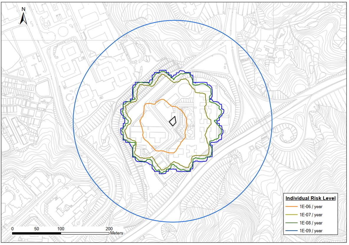
11.12.2 The maximum
individual risk contour of 1×10⁻⁶ per year contour extends
approximately 60m from the LPG Compound. Given there is no offsite risk with
frequency greater than 1×10⁻⁵ per year, individual risk is
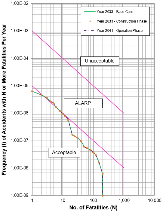
considered acceptable and in compliance with the Hong Kong Risk Guidelines. Part
of the FN curve (i.e. between 3 and 6 fatalities) falls within the “ALARP”
region and this trend is applicable for all assessed scenarios (i.e. Year 2033
– Base Case, Year 2033 – Construction Phase and Year 2041 – Operation Phase). The
total PLLs for all assessed scenarios were found to be about 3.84×10⁻⁵
per year and the proposed Project works area accounts for 2.87×10⁻⁸ per
year (0.07% of total PLL) during construction phase. Thus, the PLL
contribution to the proposed Project works area as compared with the overall
risk level was considered negligible. Nonetheless, risk mitigation measure,
i.e. installation of gas detectors was proposed following the ALARP principle. Based
on the cost-benefit analysis, the proposed mitigation measure to install gas
detectors with PLL reduction of 2.87×10⁻⁸ per year was considered
economically unviable since ICAF (i.e. HK$5.82×10¹¹) was found to be
significantly larger than the adjusted Value of Life (i.e. HK$660M).
11.12.3 Although the
proposed mitigation measure was considered economically unviable for PLL
reduction during construction phase, the following “Good Practices” are
proposed to limit the number of causalities and/ or fatalities:
·
Establishment
of emergency response plans;
·
Safety/
emergency response training and drills for all personnel; and
·
Maintain
the number of construction workers onsite to a minimum.
11.13
References
[1] EMSD (2004). “Code of Practice for Hong Kong LPG Industry -
Module 3 Handling and Transport of LPG in Bulk by Road”, Issue 1, February
2004.
[2] Transport
Department. (September 2020). The Annual Traffic Census 2019.
[3] ERM
(1996). Quantitative Risk Assessment of 18 LPG Installations in Public Housing
Estates: Choi Po Court.
[4] Reeves, A.B., Minah, F.CC. and Chow, V.H.K. (1997).
“Quantitative Risk Assessment Methodology for LPG Installations”, Conference on
Risk & Safety Management in the Gas Industry, EMSD & HKIE, Hong Kong.
[5] Ling
Chan + Partners Limited. (2001). Environmental Impact Assessment for Proposed
Headquarters and Bus Maintenance Depot in Chai Wan (BDEIA) (AEIAR-045/2001).
[6] ERM
(2000). Environmental Impact Assessment for Construction of an International
Theme Park in Penny’s Bay of North Lantau and its Essential Associated
Infrastructures.
[7] MEMCL (2003). Quantitative Risk
Assessment for the Proposed Petrol cum LPG Filling Station at Cornwall Street
[8] Technica
Limited (1989). Tsing Yi Island Risk Assessment. A report prepared for the
Electrical and Mechanical Services Department of Hong Kong Government.
[9] HKO. A Wake Up Call from
Mangkhut.
https://www.hko.gov.hk/en/blog/00000216.htm
[10] Health
and Safety Executives (1997). The Calculation of Aircraft Crash Risk in the UK.
J P Byrne
[11] Health
and Safety Executive (HSE), Application of QRA in Operational Safety Issues,
RR025 (2002).