Page
2.......... Project Description
2.3....... The Need
for the Project
2.4....... Project
Location and Site History
2.5....... Scope of
the Project
2.6....... Continuous
Public Involvement
2.7....... Consideration
of Alternative Options
2.8....... Construction
Methodologies
2.9....... Construction Programme
LIST OF TABLES
Table 2.1 Design Treatment Capacity and
Effluent Standards
Table 2.2a Summary of Public
Consultation/Engagement Activities
Table 2.3 Evaluation Criteria and
Associated Key Issues and Constraints
Table 2.4 Comparison on the Five Alternative
Sites
Table 2.5 Overall Comparison between Compact-type
Technologies and CAS
LIST OF DIAGRAMS
Diagram 2.01 Trenchless pipe-laying method
Diagram 2.02 Sewage Treatment Process Schematic
Flow Diagram
LIST OF FIGURES
60334056/EIA/2.01 Project
Layout Plan
60334056/EIA/2.02 Proposed
Works Within Project Boundary (Sheet 1 of 2)
60334056/EIA/2.03 Proposed
Works Within Project Boundary (Sheet 2 of 2)
60334056/EIA/2.04 3-D
View and Typical Sections of CSTW
60334056/EIA/2.05 Layout
Plan of the Proposed Sewage Treatment Works in Caverns
60334056/EIA/2.06 Layout
Plan of the Proposed Ancillary Facilities
60334056/EIA/2.07 Overview
of Alternative Sites Locations
60334056/EIA/2.08 Alternative
Location for Supporting Facilities
60334056/EIA/2.09 Alternative
Locations for Ventilation Shaft
60334056/EIA/2.10 Alternative
Options for Emergency Outfall
60334056/EIA/2.11 Layout
of Existing STSTW
60334056/EIA/2.12 Layout
of Tolo Harbour Effluent Export Scheme (THEES) System
LIST OF APPENDICES
Appendix
2.01 Summary of Key Public
Views or Concerns on the Project
Appendix
2.02 Preliminary Programme for
Switching and Commissioning Arrangements
Appendix
2.03 Tentative Construction
Programme
2 Project Description
2.1 Introduction
2.1.1.1 This section gives a detailed description of the Project as well as provides details of the alternative options considered, and the constraints and considerations assessed in adopting the Project details as described.
2.2 Project Objectives
2.2.1.1 The proposed Project is for the development of a new sewage treatment works (STW) in caverns to be constructed at Nui Po Shan, A Kung Kok, Sha Tin, to replace the existing STSTW.
2.3 The Need for the Project
2.3.1 Need for the Development
2.3.1.1 There is a need to optimise the supply of land by sustainable and innovative approaches to support the social and economic development of Hong Kong. Relocating STSTW to caverns can release its present site for other beneficial uses.
2.3.2 Scenario without the Project
2.3.2.1 The “without the project” scenario considers the implications of not having the STSTW to be relocated to caverns.
2.3.2.2 STSTW was first commissioned in 1982, it has been in operation for over 30 years and many facilities (especially Electrical and Mechanical (E&M) plant) will be approaching their normal design life in the next one to two decades. The sewage treatment facilities would continue to age and this is likely to result in increased maintenance needs, necessitating in the longer term substantial rehabilitation / modernisation of the existing STSTW. Otherwise the frequency of plant failure would increase and the efficiency and capacity of the plant will be affected, which may in turn cause environmental impact such as increased probability of discharging inadequately treated sewage, release of odour and increase in volume of sludge to be disposed.
2.3.2.3 Besides, if the Project were not to proceed, the opportunity to release the existing STSTW site for further and community development would be lost.
2.3.3 Scenario with the Project
2.3.3.1 Upon relocation of the STSTW to caverns, 28 ha of land in Sha Tin with sea frontage can be released for re-development to meet the needs of the society.
2.3.3.2 The living environment of the surrounding area would be improved. The common potential impacts of a STW, particularly odour and visual impacts, can be very effectively controlled and minimised. Odour management of the STSTW would be greatly enhanced since the caverns would serve as very effective natural barriers.
2.3.3.3 Advanced technologies can be adopted for the new sewage treatment facilities to enhance operation process performance, resilience and reliability, as well as operation efficiency.
2.3.3.4 Subject to subsequent planning, the released STSTW site will provide opportunities for developing a green and vibrant waterfront living environment with ample open space, a continuous promenade and recreational facilities such as amenity areas, cycle tracks and other leisure purposes could be created.
2.3.3.5 The development opportunities of the surrounding area adjacent to the existing STSTW site would be enhanced after completion of the Project and the accessibility of the area would be improved by improving transport infrastructure at the area.
2.3.3.6 The project location is rich in granite. Excavation of caverns will produce a large amount of hard granitic rocks, which are valuable natural resources for construction use. Rocks produced under this Project would become a local source to support the construction industry.
2.4 Project Location and Site History
2.4.1.1 The existing STSTW is located at the estuary of Shing Mun River, and provides secondary treatment with disinfection to sewage collected from the Sha Tin and Ma On Shan areas. It has a design treatment capacity and effluent standards as follows:
Table 2.1 Design
Treatment Capacity and Effluent Standards
|
Design Treatment Capacity |
340,000m3/day (ADWF) |
|
|
|
|
|
|
Determinand |
Percentile Standard |
Upper Limit |
|
Suspended Solids (mg/L) |
30* |
60 |
|
Biochemical Oxygen Demand (5 days, 20oC) (mg/L) |
20* |
40 |
|
Total Nitrogen (mg/L) |
20# |
35 |
|
Ammonia Nitrogen (mg/L) |
5# |
10 |
|
E. coli (count/100 mL) |
1,000^ |
15,000* |
Notes:
*
at 95-percentile
#
annual average
^
monthly geometric mean
2.4.1.2 Following detailed population projection and flow assessment of the broad Sha Tin area, the design treatment capacity and effluent standards of the relocated STSTW would be the same as those of the existing STSTW.
2.4.1.3 The proposed STSTW relocation site is at Nui Po Shan of A Kung Kok on the southern side of Shing Mun River. The present zoning of the site is Green Belt. There is no major previous development. Minor tracks exist on the hillside and are used by nearby villagers and hikers which would not be affected by the Project.
2.4.1.4 For housing the sewage treatment facilities of the relocated STSTW, a series of caverns connected by cross adits will be constructed, complete with ventilation shafts and access tunnels. The outlet of ventilation shafts will be situated at a remote location on the hill away from the local community. Some ancillary facilities such as administration buildings, ventilation buildings, an information centre, transformer houses and the like would be located outside the caverns near the portals of access tunnels.
2.5 Scope of the Project
2.5.1.1 The Project comprises the following components:
(i) Construction of caverns at Nui Po Shan for housing the CSTW;
(ii) Construction of a secondary STW including sludge treatment facilities inside the caverns, with a design capacity of 340,000 m3/day at average dry weather flow (ADWF);
(iii) Construction of the main and secondary access tunnels and portals for access to the CSTW;
(iv) Construction of ancillary facilities to the caverns, including ventilation system, fire services, safety measures, communication systems, utilities, etc;
(v) Site formation and construction of ancillary facilities including a multi-storey administration building with laboratories, workshops, staff office, visitor facilities, etc, ventilation building, electrical substation, and other minor buildings and internal access road at the main portal located on A Kung Kok Street;
(vi) Site formation and construction of ancillary facilities including a ventilation building, secondary electrical substation and internal access road at the secondary portal located on Mui Tsz Lam Road;
(vii) Construction of pipelines from the CSTW for connection to the existing emergency submarine outfall of the existing STSTW;
(viii) Construction of new effluent tunnels and pipelines for the discharge of treated effluent from the relocated STSTW to the existing Tolo Harbour Effluent Export Scheme (THEES) tunnel;
(ix) Associated slope stabilisation and natural terrain hazard mitigation and geotechnical works;
(x) Landscaping and architectural works;
(xi) Construction of a ventilation adit connecting the CSTW to a ventilation shaft located in Nui Po Shan, together with a surface access of around 500m length leading from the end of A Kung Kok Shan Road;
(xii) Construction of a temporary project specific magazine at Nui Po Shan next to the location for the Ventilation Shaft, with access from A Kung Kok Shan Road, for storage of explosives for up to a few days’ use for construction of CSTW, and decommissioning of it after the completion of blasting works;
(xiii) Operation and maintenance of the new STW in caverns; and
(xiv) Decommissioning and demolition of the existing STSTW.
2.5.1.2 A small portion of treated effluent, not exceeding 1,500 m3/day (0.4% of the design capacity of the CSTW), would be reused for non-potable uses including use in the laboratory, polymer solution preparation, irrigation and toilet flushing inside the CSTW, the potable water consumption of which will thereby be reduced. A water reclamation facility including membrane filtration and/or reverse osmosis would be provided in the cavern to polish the treated effluent to meet the following design standard for reuse:
|
Determinand |
Standard |
|
pH |
6.2 - 8.0 |
|
Total Suspended Solids (mg/L) |
< 2 |
|
Total Dissolved Solids (mg/L) |
<450 for Polymer Preparation, Irrigation & Cooling and Not Specified for toilet flushing, ground and facility washing & make-up water |
|
Turbidity (NTU) |
<= 2 |
|
E. coli (CFU/100 mL) |
Non-detectable |
Note: CFU = Colony-Forming Unit; NTU = Nephelometric Turbidity Unit
2.5.1.3 A temporary project specific explosive magazine, which consist of above ground single-storey structures, is proposed to be built on Nui Po Shan next to the location of the Ventilation Shaft. The magazine will be accessed from A Kung Kok Shan Road and used for short-term – in the order of a few days – storage of explosives that will be used for construction of the CSTW. The explosive magazine will be decommissioned after the completion of construction of caverns for the Project.
2.5.1.4 The current arrangement of conveying sludge from STWTW and Sai Kung Sewage Treatment Works (SKSTW) to the existing STSTW for co-dewatering and disposal will terminated when STSTW is relocated to caverns.
2.5.1.5 Under the context of EIA Study Brief No. ESB-273/2014, the “Project”, as described above, is referring to the “Sha Tin Cavern Sewage Treatment Works” (CSTW). Any environmental impacts that may arise from the upstream sewerage modification works in relation to the STSTW relocation, or from future developments on the site of the existing STSTW after its decommissioning are outside and independent from the present EIA.
2.5.1.6 Figures Nos. 60334056/EIA/2.01, 2.02 and 2.03 show the location, boundary and general layout of the Project. A schematic isometric view to better illustrate the CSTW with typical cross sections is shown on Figure No. 60334056/EIA/2.04. A preliminary layout plan of the proposed STW in caverns and a preliminary layout of ancillary facilities to be located at the Main and the Secondary Portals are presented on Figure Nos. 60334056/EIA/2.05 and 2.06 respectively. The layout of the existing STSTW is shown in Figure No. 60334056/EIA/2.11.
2.6 Continuous Public Involvement
2.6.1.1 Throughout the formulation of the preferred option, a series of public consultation/engagement activities have been held to gather comments and views from the public on the Project. The activities include a public forum, focus group meetings, community group meetings, roving exhibitions and site visits with key stakeholders such as local residents and representatives, members of district council, professionals, environmental groups, and relevant government departments/ statutory bodies etc.. Table 2.2a summarises the activities carried out during the Stages 1 and 2 public engagement processes.
Table 2.2a Summary
of Public Consultation/Engagement Activities
|
Date |
Consultation/Public Engagement Activity |
|
Stage 1 Public Engagement |
|
|
8 November 2012 |
Media Briefing |
|
November 2012 to March 2013 |
Roving Exhibitions |
|
1 Mar 2013 |
Focus Group Meeting (Environmental groups & Professional Organizations) |
|
7 March 2013 |
Briefing to Health and Environmental Committee (HEC) of Sha Tin District Council (STDC) |
|
16, 17 & 23 March 2013 |
Community Group Meetings |
|
18 June 2013 |
Technical Seminar – “The Future of Sha Tin Sewage Treatment Works – A Reflection of Nordic Countries’ Experience” |
|
Stage 2 Public Engagement |
|
|
July to October 2013 |
Roving Exhibitions |
|
20 August 2013 |
Media Interview |
|
2 & 3 September 2013 |
Focus Group Meeting (Environmental groups & Professional Organizations) |
|
14 & 21 September 2013 and 12 October 2013 |
Visits to Stanley Cavern Sewage Treatment Works |
|
28 September 2013 |
Public Forum |
|
7 November 2013 |
Briefing to HEC of the STDC |
2.6.1.2 The Project Proponent consulted the Health and Environment Committee (HEC) of the STDC on the findings and recommendations of the Feasibility Study. The Committee supported the Government to proceed with the investigation and design of the Project on 7 November 2013.
2.6.1.3 During the public engagement activities, demonstration of mini-deodourizers have been arranged to allow the participants to better understand the effectiveness of the mitigation measures to be adopted to minimise odour impact. Demonstration by vibrograph have also been arranged to demonstrate the mitigation of vibration impact during construction.
2.6.1.4
Appendix 2.01 provides a summary of the key public views or
concerns on the Project.
2.6.1.5 The views collected during the public engagement activities have been taken into consideration in the feasibility study and investigate phase of the Project.
2.6.1.6 The Project Proponent conducted the Third Stage Public Engagement between December 2015 and early March 2016 to present the latest schematic layout including the locations of portals, supporting facilities, ventilation shaft, etc; and to disseminate the outcome of impact assessments, the temporary explosive magazine arrangement, and an in-depth introduction of the Drill-and-Blast operation including the sequence of works and safety precautionary and control measures. Views collected are being consolidated and would be considered in the detailed design where appropriate. Activities conducted during Stage 3 Public Engagement are listed in Table 2.2b below:
Table 2.2b Summary of Public Consultation/Engagement
Activities
|
Date |
Consultation/Public Engagement Activity |
|
Stage 3 Public Engagement |
|
|
December 2015 to February 2016 |
Roving Exhibitions |
|
30 January 2016 |
Community Group Meeting |
|
2 February 2016 |
Focus Group Meeting (Professional Organizations) |
|
4 February 2016 |
Consultation Meeting with On Tai Alliance |
|
5 February 2016 |
Focus Group Meeting (Environmental groups) |
|
20 & 27 February 2016 |
Visits to Stanley Cavern Sewage Treatment Works |
|
10 March 2016 |
Briefing to Health and Environmental Committee (HEC) of Sha Tin District Council (STDC) |
|
6 March 2016 |
Project Briefing Session to Residents in Chevalier Garden |
|
6 May 2016 |
Project Briefing Session to Residents in the Castello |
2.6.1.7 The Project Proponent would continue to engage the stakeholders and the public to enhance mutual understanding and thereby the efficaciousness of the Project.
2.7 Consideration of Alternative Options
2.7.1 General
2.7.1.1 The design of the Project has undergone a detailed evaluation of different arrangements to arrive at the optimum planning, engineering and environmental solutions which fit together in a coherent manner. The following sections summarize the evaluation criteria and the consideration of various alternative options.
2.7.2 Criteria for Options Development
2.7.2.1 To assess the suitability of the alternative options for the relocated STSTW, a range of environmental, engineering, planning and general community disruption considerations were developed for the decision making process. Table 2.3 presents the evaluation criteria and associated key issues and constraints for the options selection process.
Table 2.3 Evaluation
Criteria and Associated Key Issues and Constraints
|
Associated Key Issues and Constraints |
|
|
CSTW and Ancillary Facilities Planning |
The following are considered more desirable: · Portals – options with less amount of earth works, slope cutting and natural terrain hazard to the ancillary buildings. · Access tunnels – options with less extent of soft ground tunneling while meeting the requirements for pipes, ventilation, fire engineering and traffic, etc. · CSTW layout – options with optimized layout of sewage and sludge treatment processes and for hydraulic performance, with less volume of construction and compact footprint while facilitating plant operation and maintenance. |
|
Engineering Issues |
· Utilities – options that require diversion of major utilities will be considered less desirable. · Traffic impact – options that may lead to significant increases in traffic volume in the construction and operation stages will be considered less desirable. · Geotechnical and geological conditions –options less likely to encounter adverse conditions will be considered more desirable. · Natural terrain hazards – options with less landslide, debris flow and boulder/rockfall hazards will be more desirable. |
|
Land Issues |
· Land resumption – options with less or no resumption of private land will be considered more desirable. |
|
Environmental Impacts |
· Ecology – options causing the least effects on species of conservation interest, such as the egretry, coral communities and their habitats and less potential ecological impact will be more desirable. · Fisheries – options with the least marine works and potential fishing ground loss and disturbance will be more desirable. · Water quality – options with less potential impact on water quality will be more desirable. · Air and noise – options with less potential noise and air quality impacts will be more desirable. · Waste management – options which generate less amount of disposal materials will be more desirable. · Landscape and visual – options which result in less potential landscape and visual impacts will be more desirable. · Cultural heritage – options which result in less potential impact to cultural heritage will be more desirable. · Health – options with less potential effect on public health will be more desirable. |
|
Sustainability |
· Options that leads to higher energy efficiency during operation will be preferred. · Options that meet sustainability considerations to a greater extent will be more desirable. |
|
Public Views |
· Options that allow closer alignment with the outcome of public engagement conducted on the Project will be considered more desirable. |
|
Costs and Implementation Programme |
· Capital and recurrent costs – options that are more cost-effective in terms of both capital and recurrent costs are more desirable. · Implementation programme – options that allow a shorter implementation programme of the Project is considered more desirable. |
2.7.3 Review of Alternative Options
2.7.3.1 A review of the alternative options considered for the Project is presented in the following sections.
2.7.4 Consideration of Alternative Site Locations
2.7.4.1 When conducting the review of the proposed relocation site, five areas adjacent to the existing STSTW were identified and compared. These five areas are: Nui Po Shan at A Kung Kok, Shek Mun, Ma On Shan, Kau To Shan South and Kau To Shan North. The locations are illustrated in Figure No. 60334056/EIA/2.07.
2.7.4.2 The relative merits and drawbacks (in terms of geological conditions, land use, environmental and sewerage arrangement) for each alternative site have been reviewed and summarized in Table 2.4 below. Nui Po Shan site is deemed the most favourable site among all alternatives.
Table 2.4 Comparison
on the Five Alternative Sites
|
Alternative
Sites |
Availability
of Land |
Geological
Considerations |
Impact
on Existing Sewerage System |
Environment |
Traffic |
|
Kau To Shan (North) |
Poor New STW in cavern will be in close proximity to various private
lots/allocated land, which is not favourable. |
Poor A number of faults crossing or in close proximity to this area, more
initial and final cavern supports required. |
Fair Long upstream and downstream pumping distance as well as long
distance to seafront for submarine outfall. High energy consumption expected. |
Good Close to low density, low-rise residential buildings at Kau To Shan
as well as the Chinese University of Hong Kong (CUHK) only. |
Fair Some traffic impacts on traffic to/from CUHK. Limited contingency
access available. |
|
Kau To Shan (South) |
Poor Access tunnel/adit for Site 1b will be in close proximity to and have
direct impact on private lots/allocated land, which is not favourable. |
Poor to fair A number of faults are mapped in this area. The number of faults,
textural variability in the granite, the number of intrusions and the variety
of rock types in this area will make cavern construction more complex and
challenging. |
Good Short upstream pumping distance but long downstream pumping distance
and long distance to seafront for submarine outfall. Moderate energy
consumption expected. |
Good Close to low density, low-rise residential buildings at Kau To Shan
only. |
|
|
Ma On Shan |
Good Minimal and issue expected. |
Poor This site will be highly constrained in between the two NW-trending
faults and the rock mass is likely to be more tectonically disturbed,
mineralized and more deeply weathered than other sites. It is considered to
be the least suitable among the 5 shortlisted sites. |
Good Long upstream pumping distance, moderate downstream pumping distance
and short distance to seafront for submarine outfall. Moderate energy
consumption expected. |
Fair Close to high density, high-rise buildings including at Hang On
Estate, Yan On Estate and Yiu On Estate. |
Very Good Some impacts on the public transportation serving residential areas,
the construction vehicles can be discharged to the highway system (Ma On Shan
Road) directly which can avoid using local roads. |
|
Nui Po Shan |
|
Very good Absence of any identifiable faults, generally consistent geological
conditions across the site and only minor mapped intrusions makes this site,
based on the currently available information, a very good site geologically
for cavern construction. |
Very good Short upstream and downstream pumping distance as well as short
distance to seafront for submarine outfall. Low energy consumption expected. |
Good Less close to high density residential buildings including Chevalier Garden,
Mui Tsz Lam Village, Tai Shui Hang Village, A Kung Kok Fisherman’s New
Village. |
Good Some traffic impacts on traffic to/from Sha Tin Hospital. Alternative
routes are available. |
|
Shek Mun |
|
Good The known fault, the photolineaments,
the known monzonite intrusion and the textural variability of the granite at
this location suggest it is slightly less suitable for cavern construction
compared to Site 3. |
Fair Long upstream and
downstream pumping distance as well as long distance to seafront for
submarine outfall. High energy consumption expected. |
Good Less close to high
residential buildings including Shek Mun Estate, The Castello, Kwong Yuen
Estate, Siu Lek Yuen Tsuen. |
Good No significant impacts on
public transportation. Alternative routes are available. |
2.7.4.3 The review confirmed that Nui Po Shan is the best site for the relocation of the STSTW. To sum up, Nui Po Shan site has the following merits and is more favourable than the others:
· The geology of this area, belonging to hard granite with no obvious weak zones and faults, is most suitable for construction of large caverns;
· This area is located in the proximity of the existing STSTW and THEES effluent expert tunnel which conveys the treated effluent from the STSTW to Kai Tak Nullah (KTN) in Wong Tai Sin for discharge (as shown on Figure No. 60334056/EIA/2.12). As such, relocating the STSTW to this area will minimise the disturbance to the whole Sha Tin District, reducing the extent of construction works due to modification of upstream sewerage and shortening the construction period;
· No private land resumption is needed; and
· This area is close to Ma On Shan Highway. With appropriate measures, the traffic impact due to the relocation of the STSTW is the minimum.
2.7.4.4 Although the direct environmental impacts related to Kau To Shan (North), Kau To Shan (South), Nui Po Shan and Shek Mun site are similar, suitable geology and close to existing highway in Nui Po Shan Sites will shorten the construction period and haul route that will also have less indirect environmental impacts than other options.
2.7.4.5 Furthermore, the position and orientation of the CSTW will avoid encroaching into the boundaries of Ma On Shan Country Park and Mui Tsz Lam and Mau Ping Priority Sites for Enhanced Conservation.
2.7.5 Consideration of Supporting Facilities Locations
2.7.5.1 Different options have been considered in determining the layout of facilities to be provided outside the caverns.
Option 1 – Location of Facilities
at Both Main Portal and Area 73
2.7.5.2 Option 1 aimed at providing facilities at both Main Portal and Area 73. This was the original arrangement proposed in the Feasibility Study Stage to limit the extent of site formation works at the portal area. However, this option will take up a considerable area of Area 73 reducing the versatility of the site. Furthermore, the connectivity with the CSTW is poor, particularly since there are the Ma On Shan Highway and the Ma On Shan Rail in between, and operation effectiveness is affected. The general layout proposed in Area 73 is indicated in Figure No. 60334056/EIA /2.08.
Option 2 – Location of
Facilities at the Portals only
2.7.5.3
Considering the demerits of
Option 1, Option 2 was developed and aimed to provide all facilities and
buildings at the Main Portal. The
extent of site formation works there will increase. In return, connectivity
among the facilities, buildings and the STW is much improved. Area 73 will not need to be
reserved for any
permanent facility of the CSTW. The portal area can be
flexibly utilized such as integration of the sewage treatment works facilities with the THEES Tunnel Portal. A layout showing the location of the
facilities outside caverns is given in Figure
No. 60334056/EIA/2.08.
2.7.6 Consideration of Ventilation Shafts Location
2.7.6.1 Different options have been considered in determining the location of the Ventilation Shaft. Two locations as shown on Figure No. 60334056/EIA/2.09 are considered:
Option A – The Location
Proposed in Feasibility Study Stage
The ventilation shaft is located at the south-west corner of the CSTW. The outlet of the ventilation shaft will be at an uphill area at approximately 240mPD. It is located far from all major residential developments and villages, the closest one being more than 700m away on plan. An odour impact assessment indicates that with this air vent location any residual odour impact will be minimal and in compliance with the requirements stipulated in the EIAO-TM. On the other hand, to allow construction of the air vent, an access road approximately 1,200m in length leading from the upper end of A Kung Kok Shan Road will need to be laid.
Option B – Revised Location in Subsequent Design Development
This location lies approximately 500m to the south-west of the Option A location. It is also very remote from all major residential developments and villages, the closest one being more than 1,000m away. The outlet of the ventilation shaft will also be in an uphill area at approximately 180mPD. At this location, the access road leading from the top end of A Kung Kok Shan Road can be much shortened to about 500m in length, with correspondingly much less soft spoil generation and tree felling works. Design of the access road alignment can follow the topography of the existing natural terrain, with much reduced the slope cutting and removal of vegetation than Option A. Odour impact assessment, as will be described in a subsequent section, indicates that residual odour impact is minimal and in full compliance with the EIAO-TM requirements. Apart from the much shortened access road, another major advantage of this option is a much reduced length of ventilation shaft, and consequently less volume of construction works for the shaft. This revised location is therefore considered as more preferable.
2.7.7 Consideration of Alternative Emergency Outfall Options
2.7.7.1 Under normal operation, treated effluent from the relocated STSTW will be conveyed by the THEES effluent tunnel for ultimate discharge into Victoria Harbour. In other or emergency situations, same as for the existing STSTW, an emergency outfall is needed for bypass of treated or partially treated effluent to Tolo Harbour.
2.7.7.2 Three options of an emergency outfall for the relocated STSTW have been considered which are shown on Figure No. 60334056/EIA/2.10 and discussed below:
Option 1 – Continued Utilization of the Existing Emergency
Outfall
The existing twin 2500mm diameter emergency outfall pipelines of STSTW will continue to be utilized after STSTW is relocated into caverns. An underwater Closed-Circuit Television (CCTV) survey conducted in September 2015 confirmed that existing outfall was in satisfactory and serviceable conditions. A new twin pipeline will have to be laid across Shing Mun River for conveying the flow from the relocated STSTW to the existing outfall.
2.7.7.3 Two alignments of the proposed new twin pipeline are identified in Option 1 (i.e. Option 1A and Option 1B). Option 1A makes use of the existing pipe bridge for cross Shing Mun River, but will necessitate a much longer alignment, a large section of which is along the heavily trafficked A Kung Kok Street. Under Option 1B, a segment of the pipeline will be laid by trenchless method across Shing Mun River. The benefits of adopting trenchless method is that no dredging of the river bed will be involved. The pipeline will be installed deep below the river bed and will not affect it. The diagram below schematically illustrates the mechanism of trenchless pipe-laying method. Among Options 1A and 1B, Option 1B is the preferred scheme in terms of both the scale of works and potential environmental impacts.
Diagram 2.01 Trenchless
pipe-laying method

The
sequence of works is given as follows:
1. Excavation and set up of launching and receiving pits;
2. Assembly of Micro-Tunnel Boring Machine (TBM);
3. Tunnel boring and mucking out;
4. Installation of pipe segments
5. Repeat Step (3) and Step (4) upon completion of pipe installation;
6. Dismantlement of TBM, and
7. Dismantlement and reinstatement of launching and receiving pits after completion of works.
Option 2 – Construction of a New Emergency Outfall
2.7.7.4 This option excludes the need to lay new pipelines across Shing Mun River, but would require the construction of new outfall pipelines. The new pipeline will have to extend into Sha Tin Hoi, owing to the presence of the protection zone of the Hong Kong and China Gas Company Limited (HKCG) submarine gas main.
2.7.7.5 Similar to Option 1, two alignments of the land-based section of the outfall are identified in Option 2 (i.e. Option 2A and Option 2B). Among these, Option 2A is the preferred scheme as it has significantly less interface with the existing high pressure submarine gas pipes in Sha Tin Hoi and Shing Mun River Channel.
Option 3 – Seawall Emergency Outfall
2.7.7.6 The use of a seawall outfall at the south bank of Shing Mun River, close to the outlet of Tai Shui Hang Channel has also been considered. Nevertheless, as the location is within the tidal section of Shing Mun River channel and the discharge will be much more concentrated than the case of a submarine outfall, the resulting water quality, in case of an emergency bypass, in Shing Mun River and the part of Tolo Harbour close to the River estuary will be inferior to the existing situation with the submarine outfall. Hence this option is not considered further.
2.7.7.7 Overall, owing to the presence of the existing submarine high-pressure gas mains, the outfall pipeline and diffusers of Options 2A have to be located much closer to the shoreline where both current velocity and water depth are much lower, and hence would be less favourable in terms of plume dilution and dispersion. In fact, the existing outfall diffusers in Option 1B are situated in a region with locally the largest lower depth and distance from the shore. Moreover, dredging works in Sha Tin Hoi would be required for the new outfall diffusers in Option 2A is required and will adversely affect water quality during construction. Apart from better performance in respect of water quality, Option 1B also makes the most use of the existing facilities and hence will involve the least amount of works and their related environmental impact. Option 1B is hence the preferred option.
2.7.8 Consideration of Alternative Treatment Level
2.7.8.1 The treatment level of an STW is dependent on its environmental settings and the mode of discharge. The aim is to achieve satisfactory water quality meeting relevant stipulations. The level of treatment of an STW will determine the effluent quality, and the mode of discharge will affect the subsequent processes including dilution, dispersion and diminution of any residual pollutants. Hence for a given environmental setting, the treatment level and the mode of discharge are closely related – a lower treatment level will require a better mode of discharge, e.g. a longer submarine outfall, and vice versa.
2.7.8.2 The existing STSTW is the largest secondary STW in Hong Kong with a treatment capacity of 340,000 m3/day (ADWF). Treated sewage effluent is discharged via the THEES tunnel and KTN to Victoria Harbour ultimately.
2.7.8.3 The present Project comprises the relocation of the STSTW at same design capacity as the existing plant. As will be described in the subsequent sections, the treated effluent will be discharged via the existing THEES tunnel, and any emergency discharge from the CSTW will be via the existing submarine outfall in Tolo Harbour, same as for the existing STSTW. Hence the environmental setting and the mode of discharge of effluent are generally the same as that of the existing STSTW.
2.7.8.4 The treatment level of the existing STSTW is secondary plus disinfection, and is able to fulfil the relevant water quality requirements. The quality of discharge to Victoria Harbour is governed by Water Pollution Control Ordinance Cap 358 (WPCO).
2.7.8.5 Following the above discussion, for the relocated STSTW, maintaining the treatment level the same as that of the existing STSTW will result in a water quality at least not inferior to the present situation. On the other hand, a lower treatment level, such as Chemically Enhanced Primary Treatment (CEPT), is likely to result in a lower water quality in the receiving waters.
2.7.8.6 In contrast to the existing ones, the treatment processes in the relocated STSTW will be newly installed and of advanced technologies. Even if the same treatment level is maintained, treatment performance and reliability will be enhanced, thereby benefiting the water environment.
2.7.8.7 Raising the treatment level to tertiary treatment will give higher quality effluent. However this will incur significantly higher construction cost as additional cavern space will be required, substantially increase the operation power consumption due to the additional treatment and added ventilation requirements to cope with the additional cavern space, increase sludge quantities, etc.
2.7.8.8 In respect of the issue of treated effluent reuse, it should be noted that Sha Tin has adopted seawater flushing. Switching the use of seawater to treated effluent will require a higher level of treatment than secondary to meet flushing water standard, with much higher construction and operation costs, as well as operation power consumption owing to the additional treatment processess. The benefits, nonetheless, are not apparent as such a switching will not give rise to conservation of freshwater resources.
2.7.8.9 In light of the adequacy of the current treatment level in meeting water quality requirements, it is both environmentally and economically unjustifiable to adopt a higher level of secondary treatment plus disinfection for the CSTW.
2.7.9 Consideration of Alternative Treatment Processes
2.7.9.1 In order to meet the required discharge quality standard, biological treatment will have to be provided. The sewage treatment process to be adopted for STSTW will generally comprise the following components, but the detailed sequencing and configuration may vary from process to process (e.g. batch reactor processes may combine several functions in a single tank): (1) preliminary treatment including fine screening and grit removal; (2) primary treatment; (3) biological treatment; (4) solid/liquid separation; and (5) Ultraviolet (UV) disinfection. Diagram 2.02 below presents a schematic flow diagram of the treatment process:
Diagram 2.02 Sewage
Treatment Process Schematic Flow Diagram
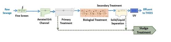
2.7.9.2 Sewage arriving at the inlet of the STW will enter the preliminary treatment process, including mechanical bar screens and grit removal system to remove large solid debris, sand and grit materials. Preliminarily treatment effluent may then be directed to the primary treatment process where the suspended solids are settled out and removed as primary sludge. The primary effluent will then be conveyed to the biological treatment where micro-organisms will be used to assimilate and remove pollutants in the sewage. Finally the secondary effluent will be disinfected by UV before discharge to the THEES tunnel.
2.7.9.3 The sewage treatment process employed in the existing STSTW is the Modified Ludzack-Ettinger (MLE) process, a relatively conventional activated sludge technology based solely on suspended growth. It is proven with a lot of operation experience locally. For present-day adoption of this technology, some enhancement measures can be incorporated to render the process more compact than that in the existing STSTW, for instance, increasing the depth of aeration tanks. This conventional activated sludge (CAS) is one of the options for the sewage treatment process for the CSTW.
2.7.9.4 There are other technologies available that, by making use of attached growth or granular forms of activated sludge, will reduce the required hydraulic retention time and thus give an overall more compact process than CAS. For the purpose of discussion here these will be called compact-type technologies. They include the Moving Bed Biofilm Reactor (MBBR); Integrated Fixed Film Activated Sludge System (IFAS); the Aerobic Granular Sludge (AGS), etc.
2.7.9.5 An outline comparison is made between the compact-type technologies and CAS in terms of excavation volume and cavern overall footprint. Traditional CAS has the longest track record and has plenty number of treatment plants with scale comparable to the relocated STSTW, Compact Technology are generally newer technology but is more compact than traditional CAS process. Traditional CAS requires larger footprint due to relatively large bioreactors and clarifiers. The table below shows a comparison of the excavation volume and size of overall footprint for the Compact-type Technologies and traditional CAS respectively.
Table
2.5 Overall
Comparison between Compact-type Technologies and CAS
|
|
Compact-type Technologies |
CAS |
|
Hydraulic
Retention Time |
Shorter |
Longer |
|
Overall Tankage |
Smaller |
Larger |
|
Approximate Cavern
Excavation Volume (Mm3) |
1.9 |
2.4 |
|
Construction Period |
Shorter |
Longer |
Note:
1.
The
excavation volume in the table is the bulk volume with an assumed
bulk factor 1.25 for rock. It includes only the volumes to house the sewage
treatment process units without any of the functional and auxiliary facilities: such as solid-liquid separation, sludge treatment,
access tunnels, other associated facilities etc.
2. The figure stated for compact-type technologies corresponds to the IFAS, MBBR and the AGS technologies. |
||
2.7.9.6 Both CAS and the Compact-type technologies will provide secondary biological treatment capable of achieving the effluent standards presented in Table 2.1 when coupled with UV disinfection. In terms of environmental impact assessment, there is no significant difference in the nature of impacts between the two options. On the other hand, owing to higher tankage volume, CAS will involve a considerably larger volume of excavation works and higher construction period during which environmental impacts will be generated. Hence compact-type technologies are the preferred option.
2.7.9.7 A preliminary schematic of the sewage treatment works is shown in Figure 60334056/EIA/2.05.
2.7.10 Consideration of Alternative Sludge Treatment Process
2.7.10.1 Sludge from the future CSTW will be conveyed to the Sludge Treatment Facility (STF) in Tuen Mun for incineration, similar to the arrangement in the existing STSTW. Prior to conveyance to the Sludge Handling Facility, a number of alternative handling options are considered:
·
Dewatering with prior anaerobic digestion, with digesters located inside the
caverns
·
Dewatering
with prior anaerobic digestion, with digesters located outside the caverns
·
Direct
Dewatering without digestion
2.7.10.2 Anaerobic digestion would reduce the volume of the sludge to be disposed of to the Sludge Incineration Facility, and allow the recovery of heat and energy from the biogas generated for utilization in the STW. Yet as biogas is inflammable, its generation inside caverns is as a matter of principle not acceptable under the prevailing fire safety policy. Overseas there are anaerobic sludge digesters located inside caverns but these are of an open-top design whereby the top of the digester protrudes above the hill surface. This design is not viable for the Project owing to the CSTW being located deep under the steep topography of Nui Po Shan.
2.7.10.3 The available space at the cavern portal area is very limited and is not sufficient to accommodate any sludge digestion facilities in addition to the other necessary supporting facilities of the CSTW. Based on a preliminary estimate, an area of around 1.8ha would be required to accommodate the sludge digestion as well as biogas storage facilities. Extensive site formation including substantial setting back of the existing green belt area would be required if space sufficient for the sludge digestion facilities is to be made available. Given the topography of Nui Po Shan, letting alone the technical requirements, the site formation works would cause significant adverse environmental impact in terms of tree felling, more geotechnical and slope stabilisation works needed, additional excavated materials to be disposed of, as well as noise and air emissions due to the additional excavation works.
2.7.10.4 In view of the issues arising from the inclusion of anaerobic digestion at the relocated STSTW, either inside or outside the caverns, the direct dewatering option is the most feasible option for this Project. The sludge will be dewatered to a dry solids content of 30% minimum.
2.7.11 Consideration for Alternative / Phased Installation in relation to Flow Projections
2.7.11.1 The relocated STSTW is to be constructed inside caverns by drill & blast method as described in Section 2.8.2 below. Unlike expanding an open-plan sewage treatment works, it will be subject to many more constraints to excavate part of the caverns only at the initial stage and return to excavate the remaining portion at later stage when the flow builds up, because the vibration to be caused by the blasting works may affect the integrity of the structural elements and the E&M equipment which already installed within the same cavern network.
2.7.11.2 Based on the current programme, the relocated STSTW is expected to be commissioned by 2027. According to the recent flow projection based on the latest population data available from the Planning Department, i.e. Territorial Population and Employment Data Matrices (TPEDM) -2011 enhanced version, the projected flow in 2027 would be around 290,000 m3/day and the projected flow at the ultimate scenario would be around 340,000 m3/day (ADWF).
2.7.11.3 Since the difference in projected flows between the time when the relocated STSTW is commissioned and the ultimate design scenario is about 15% only, it is considered appropriate to construct all the caverns and civil works in one go. Installation of the E&M equipment can phase with the flow build-up. The detailed phasing can be determined at a later stage with consideration of population growth at the time when the sewage treatment installations are procured.
2.7.12 Consideration to Minimise Emergency Discharges
2.7.12.1
The following measures will be
adopted to ensure the reliability and to minimise the risk of emergency
discharge of the relocated STSTW:
·
Provision
of sufficient standby units for all major treatment units E&M equipment to
cater for equipment breakdown and maintenance needs, which in turn will
minimize the risk of inadequately treated effluent or emergency discharge;
· Provision of dual power supply from two separate electrical sub-station to the sewage treatment works. Normally power supply to sewage treatment works will be from a single 132kV source and fed into two 11kV systems. For the CSTW, dual 132kV supply will be provided by two separate electrical sub-stations which individually is sufficient for full power supply of the plant. This greatly lowers the probability of power outage. Hence, the reliability of power supply will be much more secured than the case of most other sewage treatment works; and
· commissioning of the relocated STSTW is planned to be carried out in stages. A portion of the total flow will first diverted to the relocated plant to enable the treatment process to be tested, refined and adjusted to the required performance before the remaining sewage is diverted to the relocated STSTW.
2.8 Construction Methodologies
2.8.1 Introduction
2.8.1.1 This section describes the planning of the construction of the Project, covering the key aspects including the envisaged construction methods of tunnels, caverns and other ancillary structures, decommissioning and demolition of existing STSTW and the sequence of works.
2.8.2 Construction Methods for Tunnels and Caverns
2.8.2.1 Based on the available geological profile, it is envisaged that the tunnels and caverns excavation will be mostly carried out in good quality granitic rock mass. They are typically excavated by either Drill-and-Blast or by TBM. Other forms of excavation such as mechanical and chemical splitting are not cost effective except for either small volume of excavation or at locations where blasting would pose too great nuisance or be hazardous.
Tunnel Boring Machine (TBM)
Method
2.8.2.2 TBMs are normally adopted for construction of small to medium size tunnel. The largest TBM machine currently available in the world is the one being used for the construction of the sub-sea tunnel of Tuen Mun – Chek Lap Kok Link with a diameter of about 17m. The size of the caverns required for the sewage treatment works is 24m and above in general which is much beyond the maximum size of TBM available in the market. Adoption of a smaller cavern span will result in more number of process trains and flow control would be more complicated. Furthermore, the cavern formed by TBM will be generally circular in shape, which is not an effective shape for the sewage processing units. This in turn may require more cavern area and hence a larger overall footprint. The CSTW site is bounded by the existing effluent tunnel of the THEES on the western side and the Ma On Shan Country Park on the east. Increasing its footprint will likely encroach into these sensitive features which is highly undesirable.
2.8.2.3 Besides, the levels and heights of individual process caverns along the process train will vary in order to suit the plant hydraulics. Thus it is technically complicated to have a single TBM drilling through the entire process train. Other considerations such as the need for a considerable open space for TBM launching and the need for retrieval of the TBM cutterhead make the TBM option less effective. Hence, adoption of TBM for constructing the caverns is not considered a practical solution for this Project.
Drill-and-Blast Method
2.8.2.4 Drill and blast method is a cyclic operation comprising: drilling of charge holes for the explosives, blasting of the rock face and removal of the spoil either concurrent with, or prior to, the installation of temporary support. In addition to the basic components of the drill and blast cycle, ground treatment such as pre-excavation grouting is required if the alignment passes poor ground. Drill and blast excavation has been proven to be very efficient for excavation of tunnels and caverns where multiple faces can be excavated simultaneously.
2.8.2.5 The overall duration of the cycle will be largely dependent on the time taken to drill the face, and the time taken to muck out the blasted rock. It is therefore possible to adjust the advance per blast in order to achieve an optimum production rate. Drill and blast method is hence a very flexible solution conducive to completing the cavern construction within the allowable working period.
2.8.2.6 Typically the excavation phase is completed before the permanent lining is constructed. Prior to the provision of the permanent lining, temporary support is required where necessary to secure the opening. The temporary support comprises various elements including: rock bolts/dowels, shotcrete, and steel arches used either singly or in combination depending on the nature of the rock mass.
2.8.2.7 The permanent lining normally comprises cast-in-situ concrete but could also comprise high quality shotcrete in combination of rock dowels.
2.8.2.8 When excavating through water bearing ground, control of water inflow only be done by methodical injection excavation. Continuous probing as the face advances will ensure that any water bearing zones or discrete features are located and pre-treated.
2.8.2.9
The environmental impacts due to
these two construction methods are similar as the construction of caverns is
basically carried out in underground.
However, TBM has a number of limitations related to the available TBM
size, varying cavern sizes and geometry along process trains, to suit the
treatment process, the need of a sizeable launching space, etc., so it is not
the most effective solution in this Project.
For the
construction of access tunnels and caverns, the Drill-and-blast
method would suit the nature and scale of the works Project better that
TBM. On the other hand, for the
laying of pipelines below Shing Mun River or in hard rock, smaller-size TBM is
considered an appropriate method.
2.8.3 Consideration of Alternative Temporary Explosive Magazine Arrangements
2.8.3.1 The scenario of not having an on-site temporary magazine has been considered. Under such a situation, explosives availability at the works fronts will be dependent totally upon explosives delivery by the Mines Division of CEDD, which normally is limited to once per day and in any case would be subjected to resources limitations of the Mines Division. For a project with multiple large-scale caverns like the STSTW Project, this will pose a serious constraint on the construction programme and unnecessarily prolong the construction period, with a significant delay in realizing the environmental benefits of the relocation Project. A broad-brush assessment indicates that without an on-site explosive magazine, the pace of construction of the caverns will be limited by the inevitably small number of concurrent blasting workfronts and as a result the overall construction time of the Project will be prolonged by at least 10 years. This will in turn imply a much lengthened construction phase during which the environment may be subject to potential environmental impacts, and a significant delay in realizing the environmental benefits of the relocation Project. This scenario is therefore undesirable in environmental aspects.
2.8.3.2 The option of shared use of other existing magazine sites with other contracts have also been considered. There are three magazines recently in operation namely the magazine sites at Tseung Kwan O Area 137, Ta Shui Ha and Chung Hom Shan. The delivery of explosive from Chung Hom Shan to Sha Tin across Victoria Harbour is only allowed in restricted hours and weather conditions which will pose a big constraint on the construction programme. For the other two magazines, their continued availability after completion of the projects they are serving, which time would precede works commencement of the STSTW project, is highly uncertain. In addition, Mines Division of CEDD has confirmed that Kowloon Explosive Depot (KED) does not have sufficient capacity to support the operation of the STSTW construction works. Therefore, shared use of existing magazines is not a feasible alternative.
2.8.3.3 A much more environmentally sound and technically viable alternative is the provision of a temporary on-site explosives magazine.
2.8.3.4 The future CSTW will comprise a vertical ventilation shaft opening to a remote uphill area on Nui Po Shan. Construction of the shaft will necessitate the installation of an access road from the upper end of A Kung Kok Shan Road. Adjacent to the location of the ventilation shaft opening is a small flat area. This is considered a very suitable site for the temporary explosives magazine, as it is remote from population and the community – the nearest residential premises, the Neighbourhood Advice-Action Council Harmony Manor, is approximately 200m away.
2.8.3.5 To ensure the security of explosives, security fences complete with overhang covered in barbed wire will be installed around the store. Security guards will be on duty 24 hours, with a guard hut located at the entrance. The guard hut will be provided with a register of authorised persons who are permitted to enter the compound. CCTV system will also be installed to provide 24 hours surveillance and video recording.
2.8.4
Construction Methods for THEES
Connection Work
2.8.4.1 The current arrangement of discharging STSTW treated effluent to KTN through the THEES tunnel would be maintained after relocation. To convey the treated effluent of the future CSTW to the THEES tunnel, two options have been considered.
2.8.4.2 In Option 1, the connection point will be outside the THEES tunnel at its Sha Tin portal. A short section of tunnel will be constructed between the CSTW, and the THEES tunnel inlet chamber.
2.8.4.3 In Option 2, the connection point will be at a point along the THEES tunnel several hundred metres downstream of its Sha Tin portal.
2.8.4.4 Both Options will inevitably require transient suspension of the THEES tunnel at certain times for constructing the connection, during which treated effluent in the THEES will be temporarily bypassed into Tolo Harbour. For Option 1, the connection works involve modifications to the existing inlet facilities to the THEES tunnel; while for Option 2, the connection will involve breaking into the existing THEES tunnel for a T-junction and making good the tunnel lining afterwards. Both the number of times and duration of temporary suspension will be less for Option 1 than Option 2. Option 1 is therefore the preferred alternative. The arrangement of the preferred Option 1 is show on Figure No. 60334056/EIA/2.01.
2.8.4.5 It is assessed that the connection works of Option 1 can be split into a number of steps for synchronized implementation with THEES maintenance, thereby avoiding the need for additional temporary suspension of the THEES. The short-term environmental impacts of THEES maintenance, which is required in any case under the present practice irrespective of this Project, has been considered in the approved EIA Report for “Tai Po Sewage Treatment Works Stage V” (AEIAR – 081/2004).
2.8.5 Construction of Administration, Ventilation and Ancillary Buildings
2.8.5.1 Ancillary facilities including a multi-storey administration building with laboratories, workshops, staff office, visitor facilities, etc., Ventilation Building No. 1, Electrical Substation No. 1, and other smaller buildings will be located in the main portal located on A Kung Kok Street.
2.8.5.2 Ventilation Building No. 2 and Electrical Substation No. 2 will be located in the secondary portal located on Mui Tsz Lam Road.
2.8.5.3 These building structures will be of typical reinforced concrete construction with architectural features, and construction works generally include: i) formwork and falsework erection, ii) rebar fixing, iii) concrete pouring and curing, iv) formwork striking and back propping, v) installation of building services and vi) installation of large E&M equipment.
2.8.5.4 Superstructures will adopt bottom-up construction by constructing the ground floor slabs, beams, columns and walls from the low level and progressing upwards to roof level.
2.8.6 Construction of Slopes and Retaining Walls
2.8.6.1 Construction of the slopes (including natural terrain mitigation measures) and retaining walls for the Project is to a large extent governed by the following constraints/uncertainties:
·
Topographical
constraint due to sloping ground conditions of the sites;
·
Weather
condition;
·
Possible
obstructions to the construction; and
·
Geotechnical
uncertainties which include ground and groundwater conditions.
2.8.6.2 Where possible, construction programme should be arranged so that the slopes and retaining walls are constructed under favourable weather condition, preferably in dry season. Temporary drainage system shall be constructed prior to construction.
2.8.6.3 Obstructions to construction shall be verified and determined on site. Utilities and trees shall be properly treated at the onset of the construction. Natural terrain mitigation measures are normally located at areas with dense vegetation. Minimal disturbance to the environment shall be maintained during the construction.
2.8.6.4 Where existing structures and sensitive receivers are located in the vicinity of the construction area, temporary safety precaution measures shall be implemented to avoid possible damage. Instrumentation and monitoring works shall be implemented throughout the construction period to monitor the effect of the works. Groundwater monitoring data shall be collected to review the design groundwater level and hence reduce the geotechnical uncertainties where necessary.
2.8.6.5 Cut slopes and temporary cutting for retaining walls shall be formed by bulk excavation and installed with necessary slope stabilization works including soil nailing. Slope stabilization works shall be installed and stability of the excavation shall be maintained at all stages.
2.8.6.6 Earth filling including construction of fill slopes and backfilling behind retaining walls shall, in general, be compacted to at least 95% of the maximum dry density. Surface upon which fill is to be placed should be stripped of all trees, loose filling, top soil, boulders, debris of any nature and the like.
2.8.6.7 L-shaped retaining wall shall not be backfilled until sufficient strength of concrete has been achieved after concreting. Construction of cantilever retaining walls shall be completed prior to excavation in front.
2.8.6.8 Throughout the construction period, all temporary works should be subjected to regular inspections. Signs of distress in any structure or slope should be recorded and steps taken to alleviate the distress.
2.8.7 Decommissioning of the Existing STSTW
2.8.7.1 The staff quarters in the existing STSTW will have to be demolished in an early stage in order to form the site for construction of the Intermediate Sewage and Effluent Pumping Station (ISEPS) under a separate project for conveying treated effluent from Tai Po Sewage Treatment Works to THEES Tunnel.
2.8.7.2 The design treatment capacity of the existing STSTW is 340,000 m3/day (ADWF). As it is normally the case for such infrastructural facilities, this capacity corresponds to a long-term situation. The latest flow projection is that the inflow to the STSTW will not be approaching the design capacity around the time of commissioning the CSTW. For interim construction needs of the Project, some of the existing treatment processing units could be decommissioned and demolished in advance of CSTW completion while still meeting effluent standards of the plant.
2.8.7.3 Details of demolition phasing is a matter of construction planning and actual flow increase which are not precisely available at this stage. As a conservative approach for assessment purposes, air impact assessment would be carried out based on the programme as presented in Appendix 2.02, which assumes the demolition works to be carried out over a short time span which would give a more conservative assessment result.
2.8.8 Consideration of Demolition Methods
2.8.8.1 The Code of Practice for Demolition of Buildings (CDB, Buildings Department 2004) identifies several main methods of techniques for demolition including:
·
Top down methods by jack hammer, percussive or hydraulic breakers;
·
Wrecking Ball;
·
Implosion;
·
Cutting and Drilling;
·
Non explosive demolition agents (NEDA);
·
Thermal lance; and
·
Water
jet.
Implosive
Methods (blasting)
2.8.8.2 Implosion does not offer any potential reduction in polluting impacts in the form of noise, vibration and dust (ref. CDB) and is not efficient for slabs and walls that will require demolition. Therefore the preferred method of demolition should adopt a non-blasting approach and implosive demolition using a blasting approach has been ruled out as an option for demolition.
Top-Down
Methods
2.8.8.3 Top-down methods are applicable and efficient for all types of structure. Typical jack-hammers can reduce vibration and hydraulic breakers can reduce noise (ref. CDB). However, machine mounted percussive breakers and toppling or breaking away structures by large machinery do not offer any potential reduction in dust, noise or vibration emissions (ref. CDB). As these methods may not be used exclusively, in order to assume a worst case scenario, a variety of these typical methods can be assumed to be used.
Wrecking
Ball
2.8.8.4 This method is generally suitable for dilapidated buildings but would not be applicable in this case where the clear space to the edge of the Site is limited in places and structures have substantial steel reinforcement. This application also demands high level skill operators and well-maintained equipment.
Other
Methods
2.8.8.5 Potential polluting impacts in the form of noise, vibration and dust can be reduced by using methods such as circular saw cutting, wire saw cutting, and stitch drilling which are effective for all structures and can reduce vibration, noise and dust. NEDA can also reduce vibration, noise and dust but is not applicable to slabs and walls. The use of thermal lance and or high-pressure water jets would not generally be recommended unless there are no other viable alternatives. A selection of the above processes may be used by the demolition contractor for specific locations. These methods would generally result in lesser impacts (ref. CDB) and their use should not be precluded by limiting the plant to be used on Site to that used in the assessments. However for the purpose of the environmental assessment, these techniques are not assumed to be adopted in order that a worst possible case scenario is assessed.
Preferred
Methodology
2.8.8.6 A variety of top-down methods are assumed to be used and various element from a suite of powered mechanical equipment have been assumed to be in use at various locations across the Site throughout the demolition. The use of jack-hammers and hydraulic breakers is efficient and noise and dust impacts can potentially be controlled by a range of practical mitigation measures (e.g. noise barriers, dust control) familiar to the construction industry in Hong Kong. In addition, the statutory provisions under the Noise Control Ordinance (NCO) and Air Pollution Control Ordinance (APCO) control noise and dust from such operations. Where Asbestos Containing Materials (ACM) may be present in the building, the method of demolition must adopt non-explosive approach. The handling of asbestos shall follow The APCO and The Waste Disposal (Chemical Waste) (General) Regulation.
2.9 Construction Programme
2.9.1.1 The Project construction works are anticipated to commence in 2018 with completion of the Project by 2028. A tentative construction programme for the Project is provided in Appendix 2.03. This programme provides the basis for the assessments presented in the EIA Report.
2.10 Concurrent Projects
2.10.1.1 Concurrent projects in the vicinity of the Project site are identified at the following paragraphs. The status of these concurrent projects is based on the available information at the time of submission of this Report. It should be noted that the implementation of individual projects would be subject to further development and subsequent actions of the respective project proponents.
(a) Proposed works for Upstream Sewerage Facilities for the Relocation of Sha Tin Sewage Treatment Works:-
This is a DSD project which include construction of a new pumping station and modification of existing pumping stations as well as sewerage works in order to convey sewage to the CSTW for treatment. All works are expected to start at 2021 for completion in 2026.
(b) Widening of Tai Po Road (Sha Tin Section):-
CEDD is conducting an investigation study on the widening of Tai Po Road (Sha Tin Section) between Sha Tin Rural Committee Road and Fo Tan Road. Construction works are tentatively scheduled to commence in end 2017 for completion by 2021.
(c) Tolo Harbour Sewerage of Unsewered Areas, Stage II :-
This project covers the provision of sewerage to a number of unsewered areas in Sha Tin. Works are on-going and expected to be completed by 2020.
(d) Tolo Harbour Effluent Export Scheme (THEES) Upgrading :-
EPD is carrying out a study “Investigation of Tolo Harbour Effluent Export Scheme (THEES) Upgrading Options and Impacts to Tolo Harbour Water Quality”. Projects may arise accordingly for upgrading of the THEES.
(e) Public Rental Housing Development at Yan On Estate Phase 2, Ma On Shan Area 86B:-
Housing Department (HD) is conducting a feasibility study on the Public Rental Housing Development at Yan On Estate Phase 2, Ma On Shan Area 86B. Construction works are tentatively scheduled to commence in the 3rd Quarter of 2019 for completion by 2023.
(f) Home Ownership Scheme Development at Ma On Shan Road:-
HD is conducting a feasibility study on the Home Ownership Scheme Development at Ma On Shan Road. Construction works are tentatively scheduled to commence in the 2nd Quarter of 2017 for completion by mid 2021.
(g) Road Improvement Works at Ma On Shan, Sha Tin:-
HD is conducting preliminary design on the Road Improvement Works at Ma On Shan, Sha Tin. Construction works are tentatively scheduled to commence in the 3rd Quarter of 2017 for completion by 2020.
(h) Shek Mun Estate Phase 2:-
It is a HD project which is currently under construction and expected to be completed by mid-2018.
(i) Potential Reclamation Site at Ma Liu Shiu :-
CEDD is conducting a study on technical issues related to potential reclamation at Ma Liu Shui. Projects may arise subject to the outcome of the study.
2.10.1.2 Table 2.6 summarises the potential concurrent projects that would contribute to the cumulative environmental impacts during construction and/or operational phase.
Table 2.6 Existing
and Planned Concurrent Projects
|
Project |
Construction Programme |
Possible Cumulative
Impacts |
Considered in the EIA
Study |
||
|
Construction Phase |
Operational Phase |
Construction Phase |
Operational Phase |
||
|
Proposed Works for Upstream Sewerage Facilities for the
Relocation of Sha Tin Sewage Treatment Works |
Commence in 2021 for completion in 2026 |
Air Quality,
(The overlapping period is for construction of CSTW only. Since the work site of ISEPS is
located more than 300m from the study area of CSTW work site, no cumulative
noise impact is expected.) |
Minimal |
Yes |
Nil |
|
Widening of Tai Po Road (Sha Tin Section) |
Commence in end 2017 for completion by 2021 |
Nil |
Nil |
Nil |
Nil |
|
Tolo Harbour Sewerage of Unsewered Areas, Stage II |
On-going and complete by 2020 |
Water
Quality (This is a water quality improvement project with no adverse
cumulative impact expected.) |
Water
Quality (This is a water quality improvement project with no adverse
cumulative impact expected.) |
Yes |
Yes |
|
Tolo Harbour Effluent Export Scheme (THEES) Upgrading
|
Programme not available |
Nil |
Nil |
Nil |
Nil |
|
Public Rental
Housing Development at Yan On Estate Phase 2, MOS Area 86B |
Commence in 2019
for completion in 2023 |
Nil |
Nil |
Nil |
Nil |
|
Home Ownership Scheme Development at Ma On Shan Road |
Commence in 2017 for
completion in 2021 |
Nil |
Nil |
Nil |
Nil |
|
Road Improvement Works at Ma On Shan, Sha Tin (PWP
Project No.: B868TH) |
Commence in 2017 for completion in 2020 |
Nil |
Nil |
Nil |
Nil |
|
Shek Mun Estate Phase 2 |
On-going and complete by 2018 |
Nil |
Nil |
Nil |
Nil |
|
Potential Reclamation at Ma Liu Shui |
Programme not available |
Nil |
Nil |
Nil |
Nil |
2.11 Summary
2.11.1.1 The potential alternatives in implementing the Project have been evaluated above. The potential environmental performance of would be assessed in further details in the following sections of this report. Appropriate design features and mitigation measures would be recommended to minimize the potential impacts to the environment due to the construction and operation of the Project.
<End of Section 2>