This
section presents the Landscape and Visual Impact Assessment (LVIA) from the
construction and operation of the proposed LNG terminal at Black Point,
adjacent to the existing Black Point Power Station.
11.1
Assessment
Methodology
The
main components of the LVIA are as follows:
·
Description of the project;
·
Review of planning and development
control framework;
·
Baseline study of landscape resources;
·
Landscape impact assessment during construction
and operation;
·
Visual impact assessment during
construction and operation;
·
Recommendations for landscape and visual mitigation measures for both
construction and operation stage;
·
Assessment of night lighting and glare;
·
Baseline study of landscape character;
·
Landscape character impact assessment
during construction and operation, and;
·
Assessment of residual impact and
conclusion on the acceptability of the Project.
11.2
Introduction
and Project Description
The
background to the project and the general description of the LNG terminal at
Black Point is presented in Section 3.
The
following description of the major visual components of the LNG terminal and
supporting infrastructure is based on the preliminary design and will be
subject to refinement at the detailed engineering design stage. The preliminary
layout plan, which shows the key visual features of the proposal, is
illustrated in Figure 11.1.
It
must be noted that the layout presented in Figure 11.1 has been selected from a
number of alternative site layouts in view of its minimisation of landscape and
visual impacts to the Project area.
The design, dimensions and location of the LNG terminal’s structures
indicated in the preliminary layout are thus the result of a preliminary
assessment which has enabled the optimisation of the LNG terminal’s
design/layout in relation to the Project area’s landscape character (i.e.
morphology, exposure to sensitive receivers, etc.).
11.2.1
Site Area
The
LNG Terminal will be constructed on approximately 21ha of land. This will be a combination of:
·
5 ha of level land which will require
excavation.
·
16 ha of land which will be created by
reclamation.
11.2.2
Construction
Impacts.
Figure 11.2 shows the
extent of construction areas. The approximate areas are as follows:
·
Excavation / Site Levelling – 42,000 m2
·
Reclamation – 163,000 m2
·
Cut / Slope stabilisation – 34,000 m2
11.2.3
Land Excavation
Excavation
of around 5 ha of land on the northeast corner and northwest edge will require
levelling, grading and blasting. This area will be used primarily for locating
two of the LNG storage tanks.
The
initial phase of site formation, including site clearance and excavation of
vegetation, topsoil and top fragmented layers of rock, will be excavated by machine. The remaining excavation will be
conducted by drilling and blasting.
The fragmented rock will be used for the reclamation of the seawall
core, secondary and primary armour layers, road embankments and can also be
crushed for use as road base, sub-base, selected fill and blinding for
buildings. Spare rock will be
disposed of off-site in accordance with relevant regulations.
Site formation will involve cutting into the side slopes of Black Point.
The
major visual components of this work will be the resultant
cut-slopes up to a maximum height of 105m.
11.2.4
Land Reclamation
Reclamation
of about 16 ha of land will be created off Black Point using excavated
material, marine sand fill and if suitable and available, public filling
materials. The works will involve
construction of a vertical and sloping seawall. The reclamation area will be
used primarily for the LNG terminal process area and other associated
facilities, such as the lay down area and administration buildings. A future third LNG storage tank can be
constructed on the reclaimed area.
A permanent seawall comprising sloping
(approximately 680 m long) and vertical (approximately 430 m long) block-work
will be constructed around the seaward boundary of the reclamation to protect
the reclamation site from wave and tidal action.
11.2.5
LNG Jetty
The
LNG jetty will comprise of one approximately 130 m long trestle leading to the
jetty structures and unloading arms
for LNG carriers to unload LNG. The trestle
will be supported on piles and a concrete deck will be placed on top to serve
as an access road to the jetty. The
steel structure will also support pipe racks and associated facilities.
11.2.6
LNG Terminal Facilities
The
LNG Terminal Facilities and expansion areas will include installation of the
following:
(Note:
all dimensions are approximate based on a preliminary design)
·
Two cryogenic LNG Tanks with space for
a third tank for future expansion, nominal size of 90m diameter by 49m high to
the top of the dome and capacity each of 180,000 cubic metres. Alternative tank
sizes may be considered by CAPCO, however the capacity
of the tanks will be similar. The potential size of these tanks could be
approximately 64m high with a smaller diameter. In order to assess the worst
case scenario, a total tank height of 70m PD (64m tank + 6m) is shown in the
photomontages.
·
Process Area
·
Low Pressure and High Pressure pumping
systems
·
Vaporization (Re-gasification) Area
including 6 sea water vaporizers
·
Vents - the low pressure vent is 50m in
height and the high pressure vent is 60m in height.
·
Maintenance Workshop (40m x 20m x 15m
high)
·
Administration Building (50m x 20m x
4m high)
·
Guard House (10m x 5m x 4m high)
·
Utility Area (40m x 20m x 4m high)
·
Control Room (30m x 25m x 4m high)
·
Compressor Shelter (20m x 20m x 8m)
·
Unloading arms
·
Jetty control pulpit on jetty head (10m
x 5m x 4m)
The major visual component will be the proposed LNG Tanks. Separate buildings
will be required for the Process Area, Maintenance Workshop, Administration Building,
Guard House, Utility Area, and Control Room. While these buildings will be
smaller visual components they will contribute to the overall industrial
appearance of the site. Emergency
Vehicle Access (EVA) will be within the constructed area and no additional EVA
access is to be created.
11.2.7
LNG Carrier
LNG
can be transported to the receiving terminal in carriers of differing
sizes. An LNG carrier of 125,000
cubic metres is approximately 285m LOA, 43m beam and a draft of 11.3m. A class of LNG carriers of up to 215,000
cubic metres may also be considered by CAPCO and an LNG carrier of such volume
would be 315m LOA, 50m beam and 12m draft.
The
transit of the LNG carrier to the Black Point receiving terminal within HKSAR waters, will be via the pilot pickup point to the South of
Lamma Island close to the boundary of HKSAR waters. When secured alongside at the jetty,
unloading arms will be connected to the carrier.
The
discharge of LNG from the carrier takes approximately 18 hours. It will also take approximately 3 hours is required for
mooring, cool down, connecting the unloading arms, and cargo measurement. In
addition approximately 3 hours for cargo measurement, arm purging,
disconnecting arms, and unmooring. It
is envisaged, based on the terminal throughput, that one LNG carrier will berth
at the terminal every five to eight days.
In
view of this frequency, the Visual Impact Assessment and associated
photomontages in Section 11.17
include the carrier moored alongside the LNG jetty.
11.2.8
Construction program
The construction program is outlined in Part 3,
Section 3 of this EIA.
The landscape and visual mitigation works are to be
carried alongside the construction of the terminal where technically feasible.
11.3
Legislation
Requirement and Evaluation Criteria
The
methodology of the LVIA is based on Annexes
10 and 18 in the Hong Kong SAR
Government's Technical Memorandum on the
Environmental Impact Assessment Process (EIAO-TM) under the EIA
Ordinance (Cap.499, S16), entitled "Criteria for Evaluating Visual and
Landscape Impact" and "Guidelines for Landscape and Visual Impact
Assessment", respectively and
the EIAO Guidance Note No. 8/2002 “Preparation of Landscape and Visual Impact
Assessment Under the Environmental Impact Assessment
Ordinance.”
The
landscape assessment considers the impact of the proposed development on the
existing landscape and particularly on the landscape character units within
500m of the development site.
The
visual assessment analyses the impact of the proposed development on the
existing views and the visual amenity, particularly from the Visually Sensitive
Receivers (VSR) within the viewshed.
In order to illustrate the visual impacts of the proposed LNG Terminal,
photomontages prepared from selected viewpoints compare the existing conditions
with the view after construction.
The residual impacts are evaluated qualitatively, in accordance with the
requirements of Annex 10 of the EIAO-TM.
11.3.1
Planning Issues
There are currently no Outline Zoning
Plans (OZP’s) covering the proposed Black Point site (see Figure
11.3).
Therefore, the LVIA will be assessed against the baseline conditions of
the area.
11.4
LANDSCAPE
Assessment
In accordance with Annex
18 of the EIAO-TM, the landscape impact assessment will
cover the following:
·
Describe
the baseline landscape. This
section identifies and describes the landscape resources within 500m of the
development site. The existing landscape resources can be based on both
topography and vegetation. This
section will also describe edges as different Landscape Resources (LR’s).
·
Map
the distribution of the LR’s at Black Point. This
section will map both the distribution of the LR’s at present.
·
A
qualitative and quantitative assessment methodology. This is based on assessing thresholds
that can determine the magnitude of change and sensitivity to change of a
particular LR.
·
Analyse
the landscape impact during construction and operation. This section
analyses the extent to which these LR’s are affected by the proposal, using
both quantitative and qualitative assessments.
·
Discuss
mitigation measures.
This section examines landscape measures that will contribute to
reducing any landscape impacts and that will enhance the landscape associated
with the development. This may include planting, new landscaped areas and
re-vegetation. The residual landscape impacts are also analysed. Mitigation measures during construction
and operation will be discussed, at day 1 of mitigation and at year 10 of
mitigation. An analysis of the effectiveness of these mitigation measures is
provided.
·
Provide
Conclusions on the impacts of the project. These are discussed along with the Visual Impact and Landscape
Character Impacts in Section 11.22.
11.5
Baseline
Landscape Description
As specified by the brief, the area for the Landscape Impact Assessment
covers the area within 500 metres of the proposed development. The landscape
baseline study examines the potential impacts on the site and surrounding areas
in terms of both the landscape resources and the landscape character areas.
The landscape character areas and resources of the study area have been
categorized according to the presence of common elements. These include factors
such as:
· Topography;
· Vegetation type (both species and age);
· Built forms;
· Evidence on human modifications;
· Land use (past and present); and
· Edges.
11.6
Broad Brush
Tree Survey
As
outlined in the EIAO Guidance Note No.
8/2002 “Preparation of Landscape and
Visual Impact Assessment Under the Environmental
Impact Assessment Ordinance.” A broad-brush tree survey has been carried
out.
A total
of 10 tree groups were recorded within the proposed Project Area. The tree species were dominated by
native tree species such
as Ficus superba, Ficus microcarpus, Litsea glutinosa and Microcos
paniculata.
None
of the trees recorded in the proposed Project Area are rare, protected by law
or of high amenity value. Most of
the trees have reached maturity and are scattered along the northern coastline
of the headland with an average of 3 individuals within a group. Most of them are poor in form and health
condition due to overcrowding of the trees and the limited growth space at the
verge of the rocky shore. All of
the trees are between 2 and 4 metres in height, whilst crown spread is on
average 2.5 metres. The understorey
was densely occupied by native shrubs and vines including Sapium discolor, Bridelia tomentosa,
Cratoxylum cochinchinense and
Taxillus chinensis.
The
major tree groups are identified in figure
11.11
11.6.1
Landscape Resources
Seven
Landscape Resources (LR’s) have been
identified as the following:
LR1 Plantation;
LR2 Shrubland;
LR3 Shrubby
Grassland;
LR4 Stream/Channel;
LR5 Developed
Area;
LR6 Rocky
Shoreline; and,
LR7 Power
Station Edge
An understanding of the sensitivity to
change of the LR’s is important when analysing the overall landscape impact of
the project upon the LR’s.
Factors
affecting the sensitivity of change for evaluation of landscape are:
·
Quality of Landscape Resources;
·
Importance and rarity of special
landscape elements;
·
Ability of the landscape to accommodate
change;
·
Significance of the change in the local
and regional context; and
·
Maturity of the landscape.
The
degree of sensitivity of the LR’s is classified as follows:
·
High
–important components or landscape of
particularly distinctive character susceptible to small changes;
·
Medium
–a landscape of moderately valued
characteristics reasonably tolerant to change;
·
Low
–a relatively unimportant landscape
which is able to accommodate extensive change.
The following section describes each
of the landscape resources.
11.6.2
Plantation
(LR 1).
The Plantation is dominated by Acacia confusa,
Melaleuca leucadendron, Lophostemon conferta and Cassia
surratensis. The plants are generally less than 5 years old and no rare or
protected species were found. The plantation also includes an area of orchard
that contains mainly Dimocarpus longan and
Litchi chinensis.
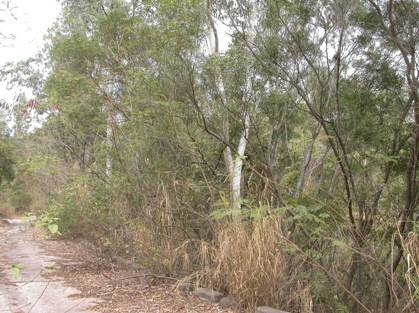
Figure 11.4 Plantation
(LR 1)
Plantation
accounts for 4.3 ha of the study area. It is an immature landscape that was the
result of human activity. Plantation
is considered to have a medium sensitivity to change.
11.6.3
Shrubland (LR 2)
The Shrubland area is dominated by
native species including Celtis sinensis, Aporusa dioica, Cassytha
filiformis, Gordonia axillaries, Litsea rotundifolia, Sterculia lanceolata and
Caesalpinia vernalis. The canopy height is generally 2-3 metres tall.
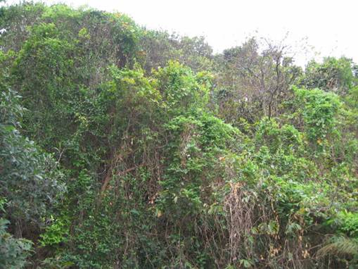
Figure 11.5 Shrubland (LR 2)
This LR is one of the most commonly
occurring LR in the study area and is relatively immature. This area accounts
for 46.6 ha of the study area. Shrubland is considered to have a medium
sensitivity to change.
11.6.4
Shrubby
Grassland (LR 3).
This area consists of grassy areas with
shrub species scattered mainly in the gully areas. The dominant species include Ischaemum
aristatum, Digitaria sanquinalis and Rhynchelytrum repens. The
general height of plants in this area is 0.5-1.5 metres.
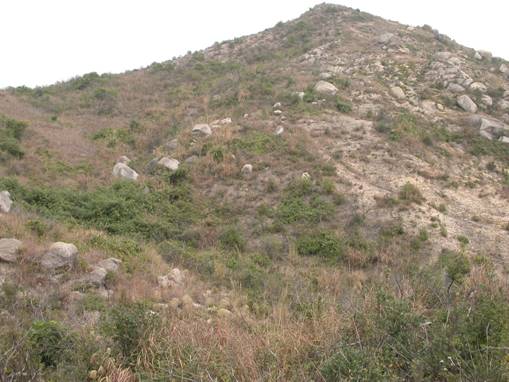
Figure 11.6 Shrubby Grassland (LR
3)
This LR accounts for 18.2 ha of the
study area. This landscape appears to be immature and the result of regeneration
following past clearing. Shrubby Grassland is considered to have a low
sensitivity to change.
11.6.5
Stream / Channel (LR 4)
This area consists of a natural stream
and two sections of storm-water drainage channel. The drainage channels are
man-made and are concrete lined.
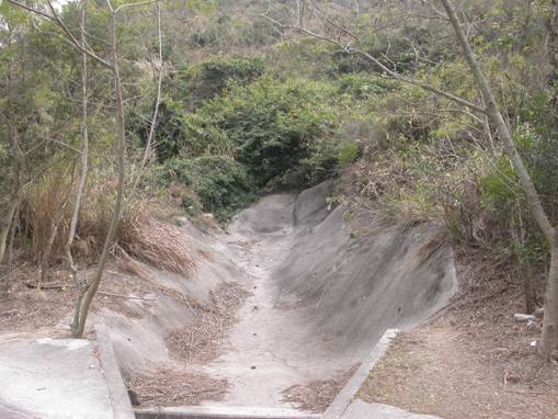
Figure 11.7 Stream / Channel (LR 4)
The drainage
channels are confined to the northern edge of
the hill slope and the stream extends a small way up the hill slope and flows into
the drainage channel. This LR covers approximately 0.7 ha of the study area.
The natural areas of the stream channel have a medium sensitivity to change,
with the man made channels having a low sensitivity to change.
11.6.6
Developed Area (LR 5)
This area is predominantly comprised of
the Black Point Power Station. There is some vegetation planted within this
area, mostly for landscaping purposes. The dominant species are: Melaleuca
leucadendron, Schefflera octophylla, Duranta repens, Cassia surattensis and
Bauhinia blackeana.
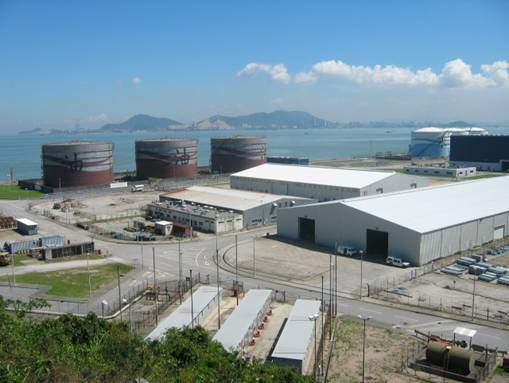
Figure 11.8 Developed area (LR
6)
This LR covers approximately 43.6 ha of
the study area and has a low sensitivity to change.
11.6.7
Rocky Shoreline (LR 6)
This is the dominant natural edge around
Black Point. It is generally comprised of rocks with some pockets of
vegetation.
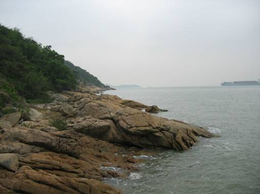
Figure 11.9 Rocky Shoreline (LR 6)
The Rocky Shoreline is an attractive
feature to mariners and visitors to the headland. This LR occupies
approximately 1.25 km of the ocean edge within the study area. The rocky
shoreline has a high sensitivity to change.
11.6.8
Power Station Edge (LR 7)
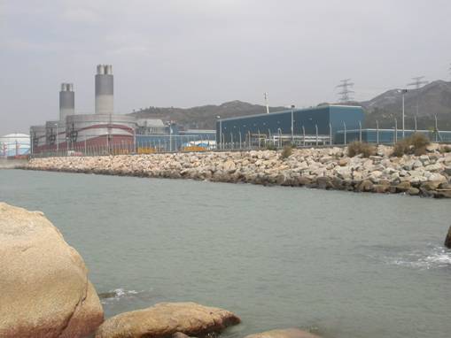
Figure 11.10 Power Station Edge (LR 7)
This is the man made armour rock
edge of the existing Black Point Power Station. It occupies 0.6 km of the ocean
edge within the study area. The Power Station Edge has a low sensitivity to
change.
11.7
The
Distribution of LR’s
Figure 11.11 shows
the present distribution of LR’s within the study area of Black Point. The most dominant unit is shrubland (41%
of the study area), followed by the Developed Area which is approximately 38.4%
of the study area.
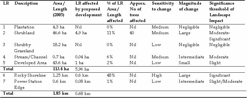
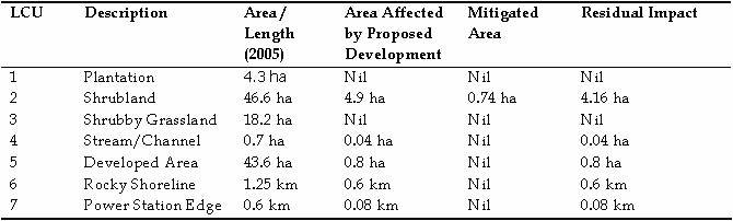
Table 11.1 Summary
Table of Baseline conditions
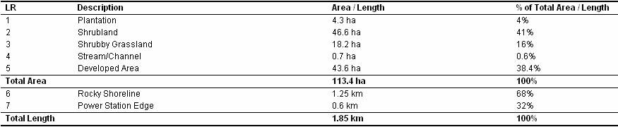
This Table shows the dominance of Shrubland and the Developed Area as
the most common LR’s. The Rocky Shoreline and Power Station Edge are similar in
length within the study area.
11.8
Landscape
Resource Impacts
The
two key factors that affect the evaluation of Landscape Resource impacts are the
magnitude of change and the sensitivity of the Landscape Resources to that
change The sensitivity to change for each of the LR’s has been described above
and the factors affecting the magnitude of change are outlined below.
Factors
affecting the magnitude of change for
assessing landscape impacts are:
·
Compatibility of the project with the
surrounding landscape, i.e. how well does the proposed development fit with its
surroundings. For example, a new housing development constructed in an area
with other housing developments or built forms will have a higher
compatibility.
·
Scale of the development, ie; how big
is the development relative to its surroundings. For example a 30 storey
building constructed on Hong Kong harbour is
considered ‘small scale’. However, the same development constructed in Sai Kung
would be considered ‘large scale’
·
Reversibility of change. This refers to
how easily the changes on the landscape can be reversed. For the purposes of
this assessment, we have assumed the terminal changes are ‘irreversible’.
The
magnitude of change is classified as follows:
·
Large
– notable change in the landscape
characteristics over an extensive area ranging to very intensive change over a
more limited area;
·
Intermediate
– moderate changes to a local area;
·
Small –
changes to specific landscape components;
·
Negligible
– no substantial changes to the
baseline condition.
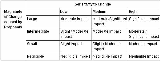
The
landscape impact is a product of the magnitude of change the Terminal will have
and the sensitivity of the Landscape Resources to that change. Table 11.2 shows the significance
threshold of the Landscape Resource impacts.
Table 11.2 Significance
Threshold of Potential Landscape Resource
Impact
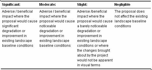
Table
11.3 provides some definitions of the significance
thresholds for Landscape Impacts.
Table 11.3 Adverse /
Beneficial Impact of Landscape Impact
11.9
Unmitigated
Landscape Impacts during Construction
Table 11.4 shows
the potential impact of the proposed development on each of the LR’s and the
potential overall impact based on the preceding Significance Threshold of
Potential Landscape Impact Assessment Matrix.
This
overall impact does not take into account the effects of remediation /
mitigation works after construction.
These will be discussed in Section 11.10
Table 11.4 Unmitigated Landscape Impact Significance
Threshold Matrix
The proposed development will impact on approximately 6 ha of the land
area and 0.68 km of the ocean edges. Figure 11.12 shows
the unmitigated potential impacts on the Landscape Resources of Black Point.
11.9.1
Summary of Landscape Impacts
Significant Landscape Impacts
The only potentially high landscape impact is on the Rocky Shoreline.
The utilization of natural rocks in the artificial walls will partly
compensate, however this is an impact of the development that will not be able
to be fully mitigated.
Moderate-Significant Impacts
Approximately 11% of the Shrubland area will be impacted. This impact would be mitigated by
remediation works that encouraged the natural regeneration of native plant
species commonly found within this LR.
Moderate landscape impacts
There will also be a moderate impact on the Stream/Channel LR’s, however
this impact will be on the more modified concrete areas with the more natural
areas being unchanged.
Slight/Moderate Impacts
There will be a slight/moderate impact on the Power Station Edge. This
area is of low sensitivity and the new terminal will create a new edge of
similar appearance.
Slight Impacts
There will be a slight impact on the Developed Area, but the new
terminal will create additional areas to replace those affected.
Negligible Impacts
There will be negligible impacts on the Plantation and Shrubby Grassland areas.
11.9.2
Landscape Impacts during operation
It
is anticipated that all of the impacts on the Landscape Resources of Black
Point will be created during the construction phase,
therefore no impacts on the Landscape Resources are expected during operation.
11.10
Landscape
Mitigation
The
final detailed Landscape Mitigation Measures will be the subject of a Landscape
Master Plan that will be submitted for approval to the relevant Authority prior
to construction.
As
mentioned in Section 11.2, the
preliminary layout assessed in this EIA Report has been selected from a number
of alternative site layouts in virtue of its minimisation of landscape and
visual impacts. The selection of
the preferred preliminary layout was determined by a preliminary landscape and
visual impact assessment of the alternative layouts.
Due to the operational requirements of the terminal, the
opportunities for the establishment of vegetation are small. A compact layout
has been adopted to allow for the operations of the terminal, meanwhile also
reducing the size of the reclamation as far as possible. Landscape berms along
the ocean edge of the terminal cannot be created as this would require
additional reclamation which is to be avoided, and landscape elements along
this edge would potentially interfere with Emergency Vehicle Access to the
site, which is mostly via marine traffic.
The
landscape mitigation measures proposed will be installed progressively
throughout the construction of the LNG terminal where technically safe and
practical. This will assist in
enhancing the effectiveness of the mitigation measures from the first day of
operation.
The
mitigation measures discussed below are proposed to reduce the potential
impacts on the existing Landscape Resources and provide a potential enhancement
of the existing landscape quality. Figures 11.13 and 11.14 show the approximate locations of the
following mitigation measures.
LMM
1 – Cultivation of areas compacted during construction.
Areas compacted during the construction phase that are not required during the
operations phase, are to be cultivated to a depth of up to 300mm in accordance
with the future Landscape Specification.
LMM 2 – Soil stabilisation and embankment planting.
During the design process a soil stabilisation and embankment planting strategy
will be developed to ensure that all land affected by slope excavation can be
replanted. All soil preparation and
the selection and provision of suitable growing medium will be completed in
accordance with the relevant best practice guidelines.
LMM 3 – Tree and shrub planting.
Planting of trees and shrubs is to be carried out in accordance with the
Landscape Details and the relevant best practice guidelines. Plant densities will be provided in
future detailed design documents and will be selected so as to achieve a
finished landscape that matches the surrounding, undisturbed, equivalent
landscape types.
Note:
LMM2 and LMM3 are to provide a minimum compensatory planting area of 0.74ha of
Shrubland.
LMM4 – Utilising natural rock for reclamation. The
reclamation areas shall utilise natural rocks for the engineered sea-walls.
LMM5 – Cut
Stabilisation. Areas
of cut to be stabilised for operational requirements.
Materials and finishes of stabilisation to be selected to complement the
surrounding landscape where technically feasible. This includes the addition of
pigments and aggregates in the finished slope that complement
the existing geology of the area.
LMM6 – Bench Plantings.
Cut Slopes to have benches created to allow for plantings. Plantings will
include Shrubs and climbers to minimise the visual impact of the slope and
mitigate impact on vegetation.
LMM7
– Early Planting Works. Where technically
feasible, new plantings are to be installed during the construction works.
Due to the unknown nature of the construction timing, this mitigation is not
shown on Figure
11.13.
LMM8 – Site hoardings to be compatible with the surrounding
environment. Where possible site hoardings to be coloured to complement
the surrounding areas. Colours such
as green and light brown are recommended. As the proposed locations are not yet
known this mitigation measure is not shown on Figure 11.13
Table 11.5 Mitigated
Landscape Impacts
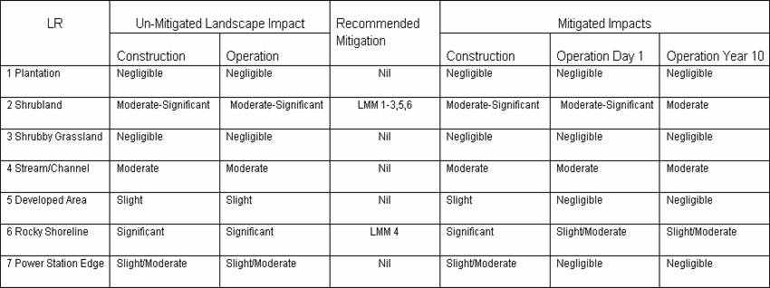
Table 11.5 describes
the predicted un-mitigated impacts on the landscape resources of Black Point in
both construction and operation phases. It also shows the predicted mitigated
impacts during construction, day 1 of operation and year 10 of operation.
No
mitigation measures are proposed for LR’s 1 and 3 as there will be no impact on
these resources. No mitigation measures are proposed for LR’s 5 and 7 as these
resources will be replaced with similar resources as a result of the new
Terminal.
11.10.1
Effectiveness of Landscape Resource
Mitigation Measures
Due
to the operational requirements of the LNG terminal, some landscape impacts
cannot be mitigated. The trees that are to be removed will be compensated by
new plantings in other parts of the headland. This will help restore some of
the more degraded areas to a more natural landscape.
11.11
Residual
Landscape Impacts
The
residual landscape impacts are those that will exist after all mitigation measures
have been implemented. Figure 11.15
shows the residual landscape impacts and they are quantified in Table 11.6
Table 11.6 Residual
Landscape Impacts
11.11.1
Residual Impact Summary
There
will be a residual impact of approximately 4.2 ha on the Shrubland area.
The
impact on the Rocky Shoreline will be partially mitigated by the use of natural
rocks in the reclamation construction. The primary Emergency Access to the new Terminal
is from the ocean, therefore landscape measures such as bunds, planters and
associated vegetation cannot be employed along the new ocean edge.
The
residual impacts on the Stream/Channel, Developed Area, and the Powers Station
Edge will be not be mitigated due to the construction
of the new terminal. As the Terminal will also be a Developed Area, the impacts
on these LR’s will be negligible.
11.11.2
Landscape Impact Conclusion
The
project will affect the Landscape Resources principally as a result of the excavation
required for the terminal. However, from the assessment it is concluded that
the Landscape Impacts will be acceptable with the implementation of the
mitigation measures.
11.11.3
Mitigation Installation and Maintenance
Responsibilities
The project proponent will be ultimately
responsible for the installation and maintenance of the mitigation measures.
A
specialist Landscape Sub-Contractor should be employed by the Contractor(s) for
the implementation of landscape construction works and subsequent maintenance
operations during a 24 month establishment period.
11.12
VISUAL IMPACT
ASSESSMENT
In
undertaking the visual assessment, the following tasks were undertaken:
1. Define the viewshed that would be
potentially impacted and map the areas of visual impact. This
section describes the viewshed of the LNG Terminal which is based on both the
planning guidelines and the parameters of human vision. This section then
utilises Geographical Information System (GIS) software to determine areas that
can potentially see the LNG Terminal.
This GIS analysis is based solely on topography and does not take into
account the screening potential of vegetation, which further reduces the actual
viewshed. GIS analysis also maps the visibility of the LNG Terminal from roads
and houses.
2. Discuss atmospheric conditions. This
section discusses the mitigating effects of weather, particularly sea haze and
rainfall.
3.
Identify
and assess indicative viewpoints as a means of assessing the visual
impact on the broader landscape. This section
describes a number of key Visually
Sensitive Receiver (VSR) viewpoints around the LNG terminal which have been
selected as indicative of the range of views from accessible locations within
the viewshed. Several viewpoints will also have photomontages or visual
simulations prepared which show the existing landscape and the landscape with
the proposed LNG Terminal site. The VSRs will be discussed to assess the visual
compatibility and severity of any obstructions or visual impacts.
4.
Discuss
visual mitigation measures. This section
examines measures incorporated into the design that will reduce potential
visual impacts such as, positioning of structures, planting of vegetation and
recommendations for material and finishes. These measures will also help
improve the overall amenity of the development. Residual impacts will also be
discussed.
5.
Assess
night lighting and glare impacts. This
section examines the potential glare and night lighting impacts associated with
the proposal.
11.12.1
Viewshed Determination & Areas Of Potential Visual Impact
The
baseline for a visual assessment is an understanding of the existing visual
qualities within the region that can be visually affected by a proposed
development. This area is referred
to as the “viewshed” or sometimes the zone
of visual influence (ZVI), or the “visual
envelope” All terms refer to the same thing, howeverthis report will use the
term “viewshed”.
Defining
an appropriate viewshed is the starting point to understand the visual impacts
of a development as the area of the viewshed will vary depending on the nature
and scale of the proposed development.
The larger a development the greater the viewshed as it may be visually
apparent for a greater distance.
Once the viewshed is established, locations can be identified within the
viewshed that are either particularly sensitive or indicative of the visual
impact for a number of locations.
In some circumstances, viewpoints may be identified beyond the viewshed
to recognise the visual impact on locations of particularly high sensitivity.
As
the viewer moves further away from the LNG Terminal, the visual impact
decreases until the LNG terminal is no longer visible. However, before the point of
invisibility is reached, the LNG Terminal has reduced in scale such that it no
longer has a significant visual impact on the landscape. In most landscapes, especially those
which have some degree of human intervention, the limit of the viewshed is
defined as that point at which the LNG Terminal would have an insignificant
effect on the view.
11.12.2
Types of Viewshed
In
recognising that the viewshed is not the limit of visibility, but rather the
extent to which an LNG Terminal would have an insignificant visual impact on
the landscape, then the extent of a viewshed differs in the context of
different landscapes.
A
viewshed in a man-modified landscape is different to a viewshed in a pristine
landscape or landscapes where there are no apparent signs of human influence.
This is because in landscapes that appear ‘natural’ or pristine, a man made
element such as an LNG Terminal, can visually influence the landscape for as
long as a viewer can discern that newly introduced element. A man made element in a pristine
landscape irrevocably changes a pristine landscape from natural to man
modified. Therefore, viewsheds in
pristine areas are extended to the limit of human visibility.
However
in man modified landscapes, in which there are many other existing built forms
or modifications to the landscape, the viewshed extends to that distance at
which the LNG Terminal become a minor element in the landscape to all but the
most sensitive of viewers.
The LNG Terminal may still be visible beyond this viewshed, however it
is considered that beyond this viewshed the visual impact will be
insignificant.
The
viewshed then is that area that is most likely to be visually impacted and once
again, it is stressed that particularly sensitive locations beyond the viewshed
may still need to be reviewed.
11.12.3
Viewshed Determination
The
visual impact of a development can be quantified by reference to the degree of
influence on a person’s field of vision.
The following diagrams illustrate the typical parameters of human vision
and are based on anthropometric data (Human Dimension & Interior
Space – A Source Book of Design Reference Standards, Julius Panero and
Martin Zelnik, The Architectural Press Ltd. London, 1979). This data provides a basis for assessing
and interpreting the impact of a development
by comparing the extent to which the development would intrude into the central
field of vision (both horizontally and vertically).
Horizontal cone of view
The
central field of vision for most people covers an angle of between 50O
and 60O. Within this
angle, both eyes observe an object simultaneously. This creates a central field of greater
magnitude than that possible by each eye separately. This central field of
vision is termed the 'binocular field' and within this field images are sharp,
depth perception occurs and colour discrimination is possible.
 These
physical parameters are illustrated in Figure 11.16 opposite.
These
physical parameters are illustrated in Figure 11.16 opposite.
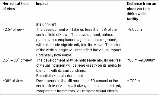
The
visual impact of a development will vary according to the proportion in which a
development impacts on the central field of vision. Developments, which take up less that 5%
of the central binocular field, are usually insignificant in most landscapes
(5% of 50O = 2.5O).
In
assessing the visual impact of the proposed LNG Terminal it is assumed that the
largest horizontal component is the entire terminal, which is approximately
400m wide.
Table 11.7 Visual Impact
based on the Horizontal Field of View
Vertical Field of View
 A similar analysis can be undertaken
based upon the vertical line of sight for human vision. As can be seen in the
Figure opposite the typical line of sight is considered horizontal or 0 O. A person’s natural or normal line of
sight is normally a 10 O cone of view below the horizontal and, if
sitting, approximately 15 O.
A similar analysis can be undertaken
based upon the vertical line of sight for human vision. As can be seen in the
Figure opposite the typical line of sight is considered horizontal or 0 O. A person’s natural or normal line of
sight is normally a 10 O cone of view below the horizontal and, if
sitting, approximately 15 O.
Objects,
which take up 5% of this cone of view (5% of 10 O = 0.5 O)
would only take up a small proportion of the vertical field of view, and are
only visible when one focuses on them directly. Objects that take up such a small
proportion of the vertical view cone are not dominant, nor do they create a
significant change to the existing environment when such short objects are
placed within a disturbed or man-modified landscape. They may however be more
noticeable in a pristine environment.
The
table below shows the relationship between impact and the proportion that the
development occupies within the vertical line of sight.
Table 11.8 Extent of impact based on distance to
tank
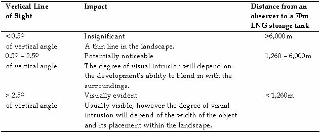
These
calculations suggest distances at which the magnitude of visual impact of the
LNG facility is reduced with distance.
At distances greater than 6000m, a fully visible LNG storage tank would
be an insignificant element within the landscape.
These
calculations seem closer to the observed distances at which levels of impact
seem to change. It is stressed that
these ranges are a guide only.
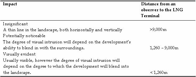
An
apparent discrepancy will occur when analysing horizontal and vertical
parameters separately. Generally,
the more conservative figures form the basis for the assessment. In this example it is proposed to extend
the viewshed to 9,000m, although it could be argued that a lesser extent would
also be valid.
For the
proposed LNG Terminal it is proposed that the following distances are used for
the Viewshed analysis.
Table 11.9 Viewshed and Degrees of Visual
Influence
It
must be noted that the areas that define the viewshed are a guide only. Simply
because a viewer moves from 1260m from the Terminal to 1270m, this will not
result in the impact moving from ‘Visually Evident’ to ‘Potentially
Noticeable’. Similarly just because a viewpoint is within either of these zones
does not indicate that a view within the viewshed will experience an impact.
Other factors such as terrain, vegetation and human-made elements in the
landscape can reduce or even remove visual impacts within the viewshed.
11.12.4
Areas of potential visual impact
A
GIS analysis can determine those areas that can potentially be visually
impacted by the development. Such
analysis is based on topography only, and shows those areas that would be
screened by intervening hills etc.
It does not account intervening vegetation or buildings, nor does it
take into account small variations in topography, such as road cuttings. Therefore it is quite a conservative
assessment of those areas that may be potentially able to view the LNG Terminal
and especially the storage tanks.
Figure
11.18 shows an
analysis of those areas within a 9km viewshed that may be able to see any part
of any of the proposed storage tanks.
The
viewshed is divided into two zones.
The zone of greatest potential visual impact are
those areas that lie within 1260m of the LNG Terminal. Since the terminal is
shielded by the Black Point Headland Hill, nearly all of this area (shown in
green) is on the ocean side of the terminal.
Table 11.10 Analysis of the areas that
lie within the viewshed where any part of the LNG tanks would be visible
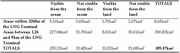
This
analysis shows that the main views to the entire LNG tank will be from the
water. Land based viewing locations
are only available within 3.33% of the 310km2 viewshed.
A
similar analysis showing those areas from which the entire LNG tank would be
visible was conducted to identify those areas of greatest potential
impact. This analysis showed far
less impacts than in the preceding analysis since it precludes areas that may
be able to see a proportion but not all of the LNG
tank.
Figure
11.19 shows the
viewshed where an entire tank is visible. Again, the viewshed is mostly
restricted to the ocean areas.
Table 11.11 Analysis of the areas that
lie within the viewshed where an entire tank of the LNG terminal would be
visible
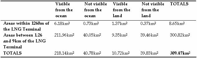
This
analysis demonstrates that the majority of the area that may be potentially
impacted lies on the ocean. Land
based vantage points are very limited and only represent 3.5% of the total
viewshed of 309km2.
The
next section of the visual analysis will select viewpoint locations on land
that lie within those areas that can potentially view the proposed LNG
terminal. Those areas are generally
restricted to coastlines, where intervening topography cannot screen views, and
along ridges in the higher areas that also have views towards Black Point. As
there will also be some marine VSR’s affected, these are also assessed.
11.12.5
Atmospheric Factors Which Will Affect
Visual Impact
Many
climatic conditions result in changes to visibility. For example, sea haze, rainfall and
other atmospheric conditions will alter the visibility of the LNG
Terminal. The diminution of visual
clarity bought about by atmospheric conditions increases with distance. As
the much of the areas that can see the development are located on or across the
sea, the impact of sea haze and other atmospheric conditions will reduce
visibility.
Sea Haze
Sea haze is a climatic condition along coastlines that
can reduce visibility even on days when the weather is fine. Wind which blows
across the ocean can cause a sea haze, limiting views to the site and the
proposed LNG Terminal from surrounding areas. Sea
haze is unlikely to have much impact on the visibility of the LNG Terminal when
viewed from close proximity. (i.e. less than
1.2km). When the same features are
viewed from greater distances within the viewshed the effect of sea haze will
greatly reduce visibility and any potential visual impact. This was illustrated in 2005 when ERM
was first asked to assess Black Point.
In the first six months of 2005 there were very few days of sufficiently
clear visibility to undertake a photographic survey from vantage points around
the site.
Rainfall
The effect that rainfall has on visibility can be measured
in two ways. Firstly the event of falling rain reduces visibility as the water
droplets obscure vision. This varies greatly depending on the heaviness of the
precipitation, but even light rain obscures distant objects greatly.
Secondly, the
event of rain, particularly sustained rain periods,
reduces visitor numbers. Therefore, the visual impact is reduced on those days
as less viewers
are visiting the area and looking at the site.
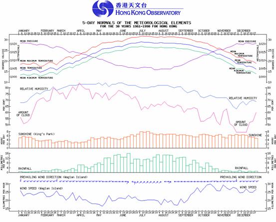
Figure
11.20 Hong Kong
Weather. Source: Hong Kong Observatory.
Figure 11.20 shows that during the wetter months, particularly from
May through September, Hong Kong receives on
average approximately 10 millimetres per day. Thus during these rain periods,
visibility is reduced.
11.12.6
Assessment Scenarios
Whilst
the above section 11.12.5 describes some of the climatic conditions that reduce
the visibility of the LNG Terminal, the following assessment will be based on a
worst case scenario that assumes perfectly clear viewing conditions. Mitigation
measures will then be proposed reduce these impacts.
11.12.7
Baseline Visual Character
The
area within the viewshed is of varying visual character and quality. The
dominant features that define the visual character are:
The
hill slopes of Castle Peak and the surrounding
area. These slopes are characterised by a mix of vegetated areas and rocky
outcrops;
The
coastal edges which vary between the rocky shoreline to the sandy beaches
further to the east;
The
ocean areas;
The
small villages areas such as Lung Kwu Tan, and;
The
large industrial facilities such as Castle Peak Power Station, The Cement Plant
and the existing Black Point Power Station.
These
elements create a visual character that is appealing but has been heavily
modified in certain areas.
11.13
VSR Assessment
There
are a number of factors that must be considered when carrying out the visual
impact assessment on the VSR’s.
VSR Sensitivity
The
first set of criteria relate to the sensitivity of the VSR’s. They include:
·
Value and quality of existing views;
·
Availability and amenity of alternative
views;
·
Type and estimated number of receiver
population;
·
Duration of frequency of view; and
·
Degree of visibility.
The
views available to the identified VSRs are rated in accordance with their
sensitivity to change using high, medium or low and are defined as follows:
· High
–
i.
The nature of the viewer groups expect
a high degree of control over their immediate environment, (eg people residing
in their homes); and
ii. The
viewer groups are in proximity to the Project. This may include viewers aboard
recreational marine vessels.
· Medium
-
i.
The nature of the viewer groups expect
a medium degree of control over their immediate environment, (e.g. drivers and passengers
in vehicles);
· Low
–
i.
The nature of the
viewer groups do not expect a high degree of control over their
immediate environment, (eg people at their place of employment or temporarily
in attendance at the VSR location).
Magnitude of Change
This
set of criteria is related to the specific details of the proposal and how it
relates to the existing landscape and the visible magnitude of change it will
cause.
The
criteria to be assessed are:
·
Compatibility of the project with the
surrounding landscape;
·
Scale of the development;
·
Reversibility of change;
·
Viewing distance;
·
Potential blockage of view; and
·
Duration of impact under construction
and operation phases.
The
magnitude of change to a view is rated as negligible, small, intermediate
or large and are defined as follows:
·
Large:
major change in view.
·
Intermediate:
moderate change in view.
·
Small:
minor change in view.
·
Negligible:
no discernible change in view.
The
degree of visual impact or significance threshold is rated in a similar fashion
to the landscape impact, ie significant, moderate, slight and negligible. The
impacts may be beneficial or adverse, however with this project,
it is assumed that all visual impacts will be adverse.
Therefore,
the visual impact is a product of the magnitude of change to the existing
baseline conditions, the landscape context and the sensitivities of VSR’s. The significance threshold of visual
impact is rated for the construction phase and for Day 1 and Year 10 of
the operation phase as described in Table
11.18
11.13.1
Photomontage Preparation
The
visual assessments are also partly based on photomontages, which show the view
with and without the terminal.
Photographs that form the base of the
photomontages are taken with a 70mm Nikon lens on a 35mm film single lens
reflex camera. A 70mm lens has a
picture angle of 34.34O and a horizontal angle of view of 28.84O.
(http://www.europepress.com/lenses/nikon_standard_zoom.htm). When two photographs taken with a 70mm
lens are overlapped approximately 1/3, the resultant image has a picture angle
of approximately 50O, which is very similar to the central cone of
view of human vision.
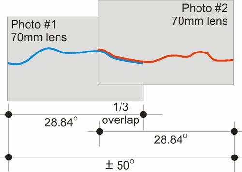
Figure
11.21 Two photographs
overlapped 1/3 to create an image approximately the same as the central cone of
view of human vision
As
discussed above, the central field of human vision is approximately 50O
- 60O. Two photographs
taken with a 70mm lens with approximately 1/3 overlap best show this static
view. A 50mm lens (picture
angle 48.45O, horizontal field of view 39.59O) is often
used for visual assessments as it is called a ‘normal lens’ because it produces
roughly the same picture angle as the human eye (about 50°). However, the 70mm lens slightly
increases the apparent size of objects in the middle and far distance and hence
increases the apparent size of the terminal in the photomontages. For this reason
this 1/3 overlap technique has been adopted for the photomontages preparation
within this report.
11.14
Visual Impact
Assessment from Visually Sensitive Receivers (VSR)
Figure
11.22 shows the indicative
viewpoints from publicly accessible locations, which have been selected for
analysis.
These
viewpoints have been selected to represent the range of views from accessible
locations. The selected viewpoints
are within publicly accessible areas, which are:
·
Public Areas
(VSR1 and VSR6);
·
Road Network (VSR3,
4 and 5); these include views seen by visitors and the local community when
traversing though along roads; The proposed Shenzhen Western Corridor/Deep Bay
link may potentially have glimpses of the development, however it is outside of
the viewshed, therefore the visual impacts it assumed to be negligible.
·
Ocean
viewpoints (VSR 2); these include views seen by
people on ferries and local boats;
·
Villages;
there are no views from villages. The proposed LNG Terminal will not be
visible from the village areas of Lung Kwu Sheung Tan and Lung Kwu Tan as the
topography of the area completely screens views. This is visible in Figures
11.18 and 11.19, where the seen area of the Terminal
does not cover any of the village areas. Similarly, whilst the GIS anaylsis has
shown that parts of Sheung Pak Nai may have glimpses of the development, site
visits to the area have shown the terminal will not be visible.
11.15
Views from
Public Areas
The two viewpoints below were selected
to represent impacts on Visually Sensitive Receivers in public areas:
VSR 1 Lung Tsai
Beach
VSR 6 Lung
Kwu Chau
11.16
Views from
Road Network
The
local road network provides opportunities to view the LNG Terminal from
publicly accessible locations.
Indicative viewpoints have been selected from the surrounding road
network and have generally been chosen at locations where views are
uninterrupted by roadside vegetation and road cuttings etc. The anaylsed
viewpoints are:
VSR
3 Above Black
Point
VSR
4 Elevated view from Lung Mun Road
VSR
5 Lung
Mun Road (Lower View)
11.17
Views from the
Ocean
The
ocean also provides opportunities for views of the proposed LNG Terminal. The GIS analysis has clearly shown that
the greatest potential viewing locations are from the surrounding ocean, not
from the land.
To
simulate the potential impacts on ocean VSR’s a photomontage has been prepared
from the eastern edge of the ferry lane. The analysed viewpoint is VSR 2, the Ferry Lane.
11.17.1
VSR1 – View from Lung Tsai Beach
Lung Tsai Beach is
located approximately 2,940 m south east of the proposed terminal. This VSR is a
public area.

Figure 11.23 VSR1
Lung Tsai
Beach
Photomontage 1 on
the following page shows that views from much of Lung Tsai beach are screened
by Black Point Headland. This viewpoint was selected as it represents a
worst-case scenario since from this angle a small part of the terminal (the
vents) will be visible.
Table 11.12 Sensitivity
/ Quality of VSR
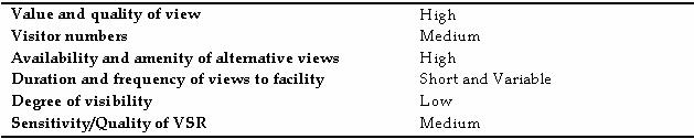
Table 11.12a Magnitude of Change
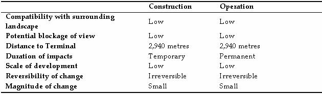
Table 11.12b
Significance Threshold during Construction
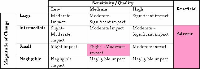
Table 11.12c
Significance Threshold during Operation

Given
the long distance from this viewpoint and the high availability of other views,
the visual impact is Slight-Moderate.
11.17.2
VSR2 – View from Ferry Lane
This
viewpoint is taken from the ferry lane edge closest to the terminal. This
viewpoint is 2010 metres to the north west of the site and is an
example as a view from the ocean.
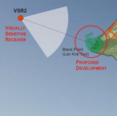
Figure 11.25 VSR2 Ferry Lane
Photomontage 2 on
the following page shows that the LNG terminal will be visible, however due to
the changing seascape and the presence of similar existing nearby facilities,
its visibility will be reduced.
Table 11.13 Sensitivity
/ Quality of VSR

Table 11.13a Magnitude of Change
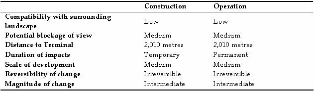
Table 11.13b
Significance Threshold during Construction
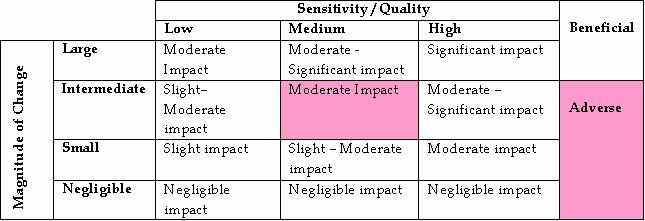
Table 11.13c
Significance Threshold during Operation

There
will be a Moderate impact from users of the ferries.
11.17.3 VSR3
– View from Above Black Point
This
viewpoint is from the end of the restricted access road above the existing
Black Point Powers Station. This viewpoint is approximately 1,035m from the
terminal.
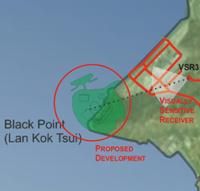
Figure 11.27 VSR3
Above Black Point
Photomontage 3 on
the following page shows that the view is dominated by the existing Power
Station facilities rather than the proposed terminal. This VSR is a view from
the Road Network. There are also very low visitor numbers to this location.
Table 11.14 Sensitivity
/ Quality of VSR

Table 11.14a Magnitude of Change
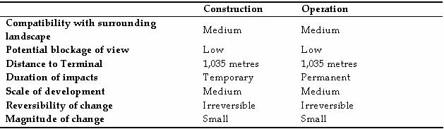
Table 11.14b Significance Threshold during
Construction
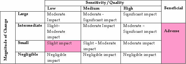
Table 11.14c Significance Threshold during Operation
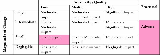
The
proposed Terminal is sited within the view of the existing Black Point Power
Plant Facility, therefore there will be a Slight visual
impact.
11.17.4
VSR4- Elevated View from Public Road(Lung Mun Road)VSR4– Elevated View from Public Road (Lung Mun Road)
This VSR is
from the Road Network. The viewpoint was selected as it is the closest view
from the Lung Mun Road
and it is approximately 1230 metres from the terminal.
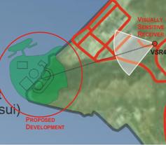
Figure 11.29 VSR4
Elevated View from Lung Mun Road
Whilst
a GIS analysis showed that the terminal would be visible from here, photomontage 4 on
the following page shows that the surrounding vegetation screens the site so
that only a small portion of the terminal is visible from this viewpoint.
Table 11.15 Sensitivity
/ Quality of VSR

Table 11.15a Magnitude of Change

Table 11.15b
Significance Threshold during
Construction
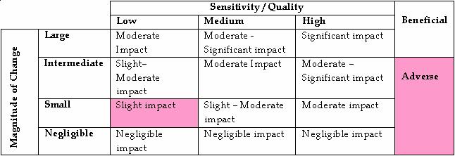
Table 11.15b
Significance Threshold during Operation
Only
a small portion of the Terminal will be visible from this viewpoint due to
existing vegetation and therefore the visual impacts will be Slight.
11.17.5
VSR5 –
View from Lung Mun Road
This VSR is also from the road network
and was selected as the topography and break in vegetation may provide views
towards the site. This viewpoint is 1555 metres south east of the site.
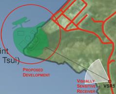
Figure 11.31 VSR5 Lung Mun Road
Photomontage
5 Vvegetation
and the existing infrastructure (container storage facility) affect visibility
to the site and therefore the terminal is not visible from this viewpoint.
Table 11.16 Sensitivity
/ Quality of VSR

Table 11.16a Magnitude of Change
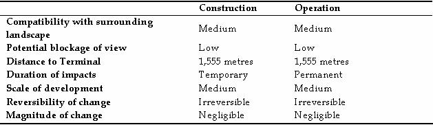
Table 11.16b Significance Threshold during
Construction
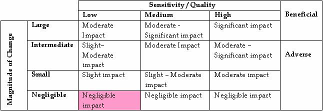
Table 11.16b Significance Threshold during Operation

The
Terminal will not be visible from this viewpoint due to existing vegetation and
therefore the visual impact will be negligible.
11.17.6
VSR6 –
View from Lung Kwu Chau
Lung Kwu Chau is a remote island located 3650 m to
the south west of the site. At this distance atmospheric affects are an
important consideration.
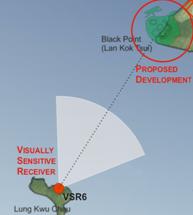
Figure 11.33 VSR6
Lung
Kwu Chau
Photomontage 6 on
the following page shows that from Lung Kwu Chau, the proposed terminal will be
visible on clear days.
Table 11.17 Sensitivity
/ Quality of VSR

Table 11.17a Magnitude of Change

Table 11.17b
Significance Threshold during Construction
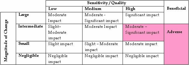
Table 11.17b
Significance Threshold during Operation

There
will be a Moderate-Significant impact from Lung Kwu Chau on days of
clear visibility. However this impact will be reduced due to the low user
numbers.
11.18
VISUAL
MITIGATION MEASURES
The
final detailed Visual Mitigation Measures will be the subject of a Landscape
Master Plan that will be submitted for approval to the relevant Authority prior
to construction.
For
those VSR’s that may experience an impact, the following Visual Mitigation
Measures (VMM’s) are proposed to reduce these impacts and provide a potential
enhancement of visual quality.
VMM 1 Design of Structures
Where possible, building structures will utilise appropriate
design to complement the surrounding landscape. Materials and finishes will be
considered during detailed design.
VMM 2 Colours
Colours
for the terminal will be used to complement the surrounding area to the extent
possible. Colours such as shades of
light grey, and light brown may be utilised to reduce the visibility of the
terminal where technically feasible.
VMM 3 Plantings
In
addition to the landscape mitigation plantings proposed earlier in this report,
appropriate new plantings will be installed to help integrate the new
structures into the surrounding landscape.
11.18.1
Alternative Site Layouts
Section 2 of
this EIA discusses the layout changes to the Black Point Terminal that have
been undertaken in order to provide a comparison and therefore reduce the
visibility of the major visible elements.
11.18.2
Mitigated Visual Impacts
Table 11.18
predicts the potential mitigated visual impacts during construction and
operation. It also predicts the mitigated
visual impacts during construction, day 1 and year 10 of operation.
Table 11.18 Mitigated
Visual Impacts
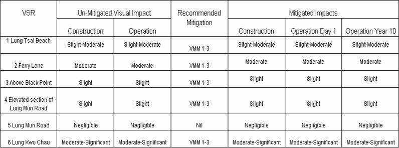
11.19
Summary of
Visual Impacts
Of
the 6 VSR’s assessed, there will be a Moderate-Significant impact on VSR6 Lung
Kwu Chau, a moderate impact on VSR2
Ferry Lane, a slight-moderate impact on VSR 1 Lung
Tsai Beach, slight impacts from VSR3 Above Black Point
and VSR4 Elevated Section of Lung Mun Road and a negligible impact from Lung Mun Road.
11.20
Night Lighting
and Glare
The
above analysis examined the visual impacts of the proposal during daylight
hours. While detailed lighting plans and specifications are not available at
this preliminary design stage, the following lighting practices will be
considered during the detailed design stage.
While
detailed lighting plans and specifications are not available at this
preliminary design stage, the following lighting practices should be considered
during the detailed design stage:
·
Security
lighting of the site boundary. These will
generally be spot lights mounted on the external fencing and will have the
beams directed towards the ground.
·
General
access lighting. This will provide safe access and operational
lighting conditions around the site. Baffles will be fitted where possible to
reduce upward light spill.
·
Emergency
lighting. These lights will provide safe levels
of illumination to facilitate evacuations or repairs in emergency situations.
The use of these lights will be infrequent.
·
Aviation
lighting. It is anticipated that some lighting
will be required at the tops of the storage tanks and vent stacks to provide
aviation safety. These lights are typically flashing coloured lights. Whilst
visible from large distances, they will not have a large contribution to the
overall ambient light levels of the site.
11.20.1
Distances
between Source lighting and VSR’s.
Due
to its remote location and the location of Black Point Headland Hill acting as a
natural visual barrier, the visibility of individual light fittings between the
affected VSR’s and the terminal is expected to be low, with any aviation
lighting on the tops of the tanks being the most visually prominent lights.
It
should also be noted that some of the climatic conditions discussed in Section 11.12.5 also apply to light
visibility and are expected to reduce night time visibility. These include rain
events and sea haze. However, very occasionally, cloud cover can increase the
visibility of night lighting in the form of reflected light. This tends to
occur when a heavy cover of low cloud sits above the site and consequently
reflects the light from beneath.
11.20.2
The
Surrounding Ambient Light of the VSR
Night
lighting from the source is more highly visible when one is observing in
darkness. As the surrounding ambient light increases, the visibility of distant
objects reduces. This includes viewers in cars, near street lights, or inside
illuminated homes. Viewers looking towards the site in complete darkness are
expected to be low in number.
11.20.3
The Surrounding Lighting Conditions of the Source.
There
are numerous sources of existing lighting from Black Point Power Station and
the nearby industrial facilities.
11.20.4
Visual
impact of night time lighting
The
above analysis indicates that potential lighting impacts will typically be low.
This is due to the following:
·
The lighting for the proposal will
generally be spot lights angled downwards and no large scale flood lighting is
proposed;
·
Most views towards the site will occur
in areas with significant ambient lighting levels, therefore greatly reducing
the visibility of distant lights;
·
There is substantial lighting
associated with the nearby industrial facilities;
·
All of the major light sources
will be pointed inward and downwards to reduce light spill.
11.21
Landscape
Character Areas
Four Landscape Character Areas (LCA’s) have been identified according to
the existing baseline conditions and the ability of the area to incorporate
change.
LCA 1 Black Point Coastal Uplands
This LCA comprises of the vegetated hill slopes with occasional
protruding rocky outcrops. The vegetation is made up of shrubland and shrubby
grasslands. There is a transmission tower near the summit of Black Point.
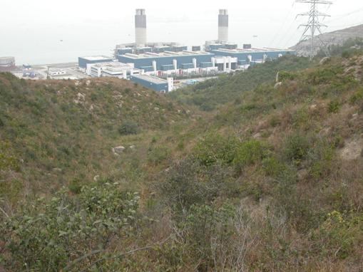
Figure 11.35 Black
Point Coastal Uplands
LCA 2 Black Point Industrial Urban Landscape
The existing Black Point Power Station
dominates this Landscape Character Area. It generally consists of berthing
areas, chimney stacks and industrial infrastructure.

Figure 11.36 Black
Point Industrial Urban Landscape
LCA 3 Offshore Waters Landscape
The Offshore Waters are characterized by large open expanses of ocean
with scattered off shore islands. There are also passing marine vessels, mostly
container ships. These areas experience high degree of remoteness.
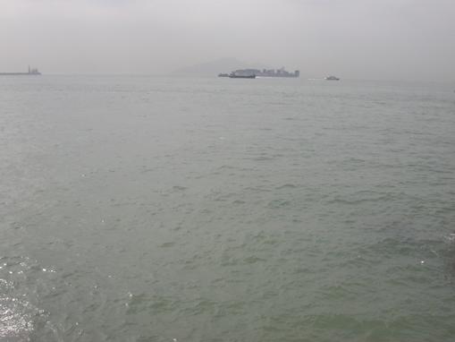
Figure 11.37 Offshore
Waters Landscape
LCA 4 Inshore Waters Landscape
The Inshore Waters experience a greater interaction with LCA 1 as the coastline visually enclose the inshore waters areas. This
LCA tends to be calmer than LCA 3 with a reduced sensation of remoteness as the
coastline offers sanctuary to the elements.
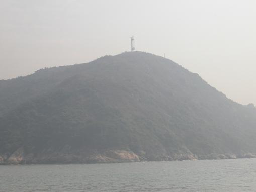
Figure 11.38 Inshore
Waters Landscape
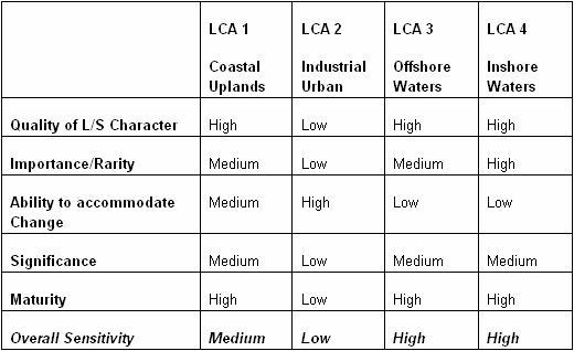
11.21.1
Factors Affecting the Sensitivity of
the LCA’s
In order to assess the impact the LNG Terminal will have on the
Landscape Character of Black Point, it is important to establish how sensitive
the landscape is to change. Generally, the more natural the landscape
character, the higher the sensitivity. The following factors will have an
affect on the sensitivity of the Landscape Character Areas.
· The general landscape quality and landscape elements of the area;
· The importance and rarity of the area or special features;
· The ability of the LCA to accommodate change;
· Significance of the change in a local and regional context; and
· The maturity of the landscape.
Table
11.19 Landscape
Character Sensitivity Matrix
11.21.2
Factors Affecting The
Magnitude of Change to the LCA’s
To establish
how large the impact will be on the LCA’s, a number of factors must be
considered. These include:
·
The projects compatibility with the
surrounding landscape;
·
Duration of the impacts under
construction and operation
·
The scale of the development
(relative to the baseline conditions of the LCA), and
·
The reversibility of change.
Table
11.20 Landscape Character
Magnitude of Change Matrix
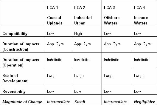
The
above table shows that there will be an Intermediate magnitude of change on the
LCA’s 1 and 3, a small magnitude of change on LCA2 and a negligible change on
LCA4. This is illustrated in Figures
11.39 and 11.40
11.22
Landscape
Character Impacts
LCA 1 – Coastal Uplands
Table
11.21 LCA 1 Coastal Uplands
Matrix
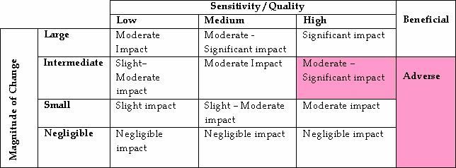
The table above shows that there will be a moderate-significant
impact on the landscape character of the Black Point Coastal Uplands.
LCA 2 – Industrial Urban
Landscape
Table
11.22 LCA 2 Industrial Urban
Landscape

There will be a slight impact on the landscape character of the
Industrial Urban Landscape. This is due to the presence of the existing
industrial facilities.
LCA 3 – Offshore Waters Landscape
Table
11.23 LCA 3 Offshore Waters
Landscape

There will be medium-significant impact on the landscape
character of the Offshore Waters areas.
LCA 4 – Inshore Waters Landscape
Table
11.23 LCA 4 Inshore Waters
Landscape
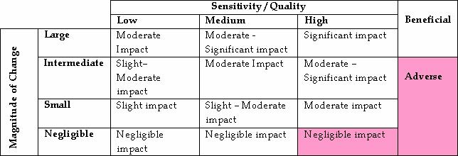
There will be a negligible impact on the landscape character of the
Inshore Waters Landscape areas.
11.23
Landscape
Character Mitigation Measures
All of the Landscape Mitigation Measures proposed in section 11.10 along
with the Visual Mitigation Measures proposed in section 11.18 will also
mitigate the impacts on the LCA’s. The final
detailed Landscape and Visual Mitigation Measures will be the subject of a
Landscape Master Plan that will be submitted for approval to the relevant
Authority prior to construction.
A summary of the effectiveness of these measures in reducing the LCA
impacts is provided below:
LMM
1 – Cultivation of areas compacted during construction.
This will assist in the re-vegetation of these areas. This will contribute to
establishing more native plants that are found in the Black Point Coastal
Uplands LCA
LMM 2 – Soil stabilisation and planting.
The addition of vegetation on the cut slopes will reduce the visibility of the
slopes and therefore assist in the ability of the LCA’s to accommodate the
project
LMM 3 – Tree and shrub planting. This
will contribute to the vegetation common to the Black Point Coastal Uplands
LCA.
LMM4 – Utilising natural rock for reclamation. This
will help integrate the edge of the reclamation into the natural rocky edge of
the Black Point area which will reduce impacts to LCA’s 3 and 4.
LMM5 – Cut
Stabilisation. Where the use of shot-crete is
un-avoidable, the addition of pigments will help to reduce the visibility of
the cut-slopes.
LMM6 – Bench Plantings.
The addition of vegetation on the cut slopes will reduce the visibility of the
slopes and therefore assist in the ability of the LCA’s to accommodate the
project
LMM7
– Early Planting Works. This will help to reduce impacts as
early as possible.
LMM8 – Site hoardings to be compatible with the surrounding environment. This
will help to reduce the impacts of the terminal during construction.
VMM
1 Design of Structures – The sensitive
design of structures will help to complement Black Point Coastal Uplands LCA.
VMM
2 Colours – The selection of suitable complementary
colour will help the LCA’s accommodate the terminal.
VMM
3 Plantings - Plantings will reduce the visibility of
the tanks and the scale of the terminal.
Design
Measures – Reducing the tank height from 70PD
to 61m PD will reduce the scale of the terminal.
11.23.1
Avoidance
The refinements discussed in section 11.2 of this report show how
the potential impacts on the Landscape Character of Black Point have been
mitigated. The impacts on the Landscape Character have been reduced by:
· The reduction of the extent of the reclamation;
· The clustering of the tanks closer together;
· The positioning of the tanks into the hill side of Black Point;
· The overall reduction in the scale of the terminal.
Table11.24 LCA Mitigated Landscape Character Impacts
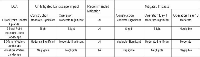
Table 11.24 above shows that when all Landscape and Visual Mitigation Measures are
in place, along with the mitigating conditions of the improved design of the
terminal, the impacts on the :LCA’s will reduce one order if significance
threshold.
11.24
Cumulative
Impacts
At present there are no
committed projects that could have cumulative impacts with the construction of
the terminal at Black Point.
11.25
Evaluation of
Residual Environmental Impacts
Taking
into consideration the baseline landscape, landscape character and visual
conditions and along with the mitigation measures, residual impacts have been
identified occurring as a result of the proposed terminal
Section 4.4.3 of
the Technical Memorandum identifies a number of factors that are to be
considered when considering residual impacts. These are outlined in Table
11.25. For the purposes
of the evaluation, an overall assessment of the impacts on the LR’s, LCA’s and
VSR’s has been carried out. It must
also be noted that this assessment is based on the overall impacts.
Table 11.25 Residual Impact
Analysis
|
Evaluation
Criteria
|
Residual
Impact Type
|
|
Landscape Resources (LR’s)
|
Landscape Character Areas (LCA’s)
|
Visual Impacts (VSR’s)
|
|
Effects on Public health and health of biota or
risk to life
|
No
effects applicable to LR’s
|
No
effects applicable to LCA’s
|
No
effects applicable to VSR’s
|
|
The
magnitude of the adverse environmental impacts
|
Overall
the impacts on the LR’s will be moderate
|
Overall
there will be negligible-moderate impacts on the LCA’s.
|
Overall
the impacts on the VSR’s will be slight-moderate with some more significant
impacts in close proximity to the terminal.
|
|
The
geographic extent of the adverse environmental impacts
|
The
impacts on the LR’s will be confined to the works area of Black Point
|
The
impacts on Landscape Character will be confined to the Black Point area
|
The
larger impacts in the VSR’s will be largely confined to areas in close
proximity to Black Point
|
|
The duration and frequency of the adverse
environmental impacts
|
The
impacts on the LR’s will be for approximately 4 years during terminal
construction.
|
The
impacts on LCA’s will be continuous for as long as the project exists.
|
The
visual impacts will be continuous for as long as the project exists.
|
|
The likely size of the community or the
environment that may be affected by the adverse impacts
|
The
area of the affected environment will be the works area of Black Point.
|
The
impacts on Landscape Character will be confined to the Black Point.
|
Visitors
to or near Black Point.
|
|
The degree to which the adverse environmental
impacts are reversible or irreversible
|
During
operation the impacts on the LR’s are irreversible. Construction phase
impacts can be mitigated through landscaping measures.
|
During
operation the impacts on the LCA’s are irreversible. Construction phase
impacts can be mitigated to the full extent practicable.
|
During
operation the impacts on the VSR’s are irreversible.
|
|
International and regional importance
|
The
adverse impacts on the LR’s do not affect an issue of international or
regional concern.
|
The
landscape character of the Black Point is valued by recreational visitors to
the area. There will be moderate adverse impacts to the existing landscape
character of Black Point.
|
The
visual quality of Black Point is valued by recreational visitors to the
area. There will be moderate to
moderate-significant adverse impacts to the existing visual quality when the
terminal is viewed at close range.
|
|
Both the likelihood and degree of uncertainty of
adverse environmental impacts
|
The
detailed assessment shows there are no uncertainties regarding the impacts on
the LR’s
|
The
detailed assessment shows there are no uncertainties regarding the impacts on
the LCA’s
|
The
detailed assessment shows there are no uncertainties regarding the impacts on
the VSR’s
|
Table
11.25 above shows that the impacts on the
Landscape Resources will have no effect on public health and are confined to the
works area at Black Point. No areas
of international or regional importance are affected and there are no
uncertainties regarding the impact.
The
impacts on the LCA’s will have no effect on public health and they are
considered to be generally moderate in magnitude. The impacts will be confined
to areas in close proximity to Black Point. Whilst the impacts are irreversible
construction phase impacts can be mitigated to the full extent practicable. There
are no adverse residual impacts on the terrestrial ecology of the area. The
landscape character of Black Point is valued by several sections of the public
and there will be some adverse impacts on this landscape character. However
this impact will be limited to the Black Point Area. There are no uncertainties
regarding the impact.
The
impacts on the VSR’s will have no effect on public health,
they will be generally moderate in magnitude and will mostly be confined to
areas in close proximity to Black Point.
There are no residual adverse impacts on areas of international or
regional importance and there are no uncertainties regarding the impact. While the VSR at Lung Kwu Chau will
experience moderate-significant visual impact, the impact will only affect a
small number of visitors to Lung Kwu Chau. Therefore the overall visual impact
from the project is considered acceptable.
11.26
CONCLUSION
·
Compensatory planting of indigenous
species will mitigate the effects of the development on many of the Landscape
Resources. The effects on the rocky shoreline can be partially mitigated by the
use of natural rock in the reclamation areas. The overall residual impacts on
the Landscape Resources are assessed as slight-moderate.
·
There will be very limited views of the
terminal from most land based viewing locations and these impacts will range
from negligible to slight-moderate. The visual impacts will be
larger for the ocean based VSR’s with moderate impacts from the Ferry Lane and moderate-significant
impacts from Lung Kwu Chau. However following consideration of the lower user
numbers in these areas and the analysis of the residual impacts, the overall
visual impact is assessed as slight-moderate.
·
Potential night time glow and
visibility of maritime and aviation lighting may be visible on clear nights
from Lung Kwu Chau and the Ferry
Lane viewing locations. However given that
significant lighting already exists at Black Point Power Station and other
nearby industrial facilities the additional night lighting from the proposed
LNG terminal is considered acceptable.
· The
Landscape Character Impacts range from negligible to moderate.
After consideration of the residual impacts, the overall Landscape Character
impacts are assessed as slight.
According
to the Technical Memorandum on the
Environmental Impact Assessment Process (EIAO-TM) the Landscape and Visual Impacts are considered acceptable with mitigation.