Chapter Title
Tables
Figures
Charts
Drawings
MCL/P132/EIA/3-001 P132 – Engineering Feasibility &
Environmental Assessment Study for Airport Master Plan 2030 Layout of Airport
Expansion Option 1
MCL/P132/EIA/3-002 P132 – Engineering Feasibility &
Environmental Assessment Study for Airport Master Plan 2030 Layout of Airport
Expansion Option 2
MCL/P132/EIA/3-003 P132 – Engineering Feasibility &
Environmental Assessment Study for Airport Master Plan 2030 Layout of Airport
Expansion Option 3
MCL/P132/EIA/3-004 P132 – Engineering Feasibility &
Environmental Assessment Study for Airport Master Plan 2030 Layout of Airport
Expansion Option 4
MCL/P132/EIA/3-005 P132 – Engineering Feasibility &
Environmental Assessment Study for Airport Master Plan 2030 Reduced Extent of
Land Formation for Option 3
MCL/P132/EIA/3-006 Preferred Airport Layout Option
MCL/P132/EIA/3-007 Proposed Ground Improvement Methods
MCL/P132/EIA/3-008 Terminal 2 Options
MCL/P132/EIA/3-009 Options for Diversion of Submarine Fuel
Pipeline
MCL/P132/EIA/3-010 Options for Diversion of Submarine 11kV
Cable
3.1.1.1
Chapter
2 of this
Environmental Impact Assessment (EIA) report discussed the expansion of Hong
Kong International Airport (HKIA) through the construction of a third runway.
This is considered necessary to meet the forecast air traffic demand up to the
Year 2030 without compromising on airport safety, airport service quality and
customer choice, and without adversely affecting the economic
benefits (such as local
employment, international business and trade) that are linked to growth in
aviation and air logistics in Hong Kong. Alternatives (to expansion) were
discussed in Chapter 2 and are considered to be inferior.
3.1.1.2
This
section identifies options and opportunities available for provision of a third
runway in Hong Kong, in terms of its alignment, the associated airport layout and construction methods.
3.1.2.1
This
section is structured as follows:
Section 3.2 – General
Considerations
presents the objectives of the airport expansion and the main constraints to
operation of the existing runways.
Section 3.3 –
Consideration of Alternatives for the Third Runway Alignment presents the runway alignment options
assessment leading to identification of the shortlisted alignments.
Section 3.4 –
Consideration of Alternatives for Airport Layout under a Three-Runway System presents the engineering and
environmental evaluation of the shortlisted airport layout options leading to
identification of the preferred option.
Section 3.5 – Further
Development of the Preferred Runway and Airport Layout presents the further considerations
and fine-tuning of the preferred option leading to the preferred runway and
airport layout.
Section 3.6 –
Consideration of Alternative Construction Methods for Land Formation presents the options for ground
improvement and seawall construction leading to the recommended construction
method for land formation.
Section 3.7 –
Consideration of Alternative Construction Methods for Marine Infrastructure
Facilities presents
the options for construction of airport facilities and infrastructure including
the runway approach lights, diversion of the submarine aviation fuel pipelines
and diversion of the submarine 11 kV cables.
Section 3.8 – References lists all the reference documents
which have been referred to in this section.
3.2.1 Objectives of Airport Expansion
3.2.1.1
The
need for airport expansion has been elaborated in Chapter 2. If a three-runway system (3RS) is developed, it must meet the
needs of the aviation
sector in Hong Kong and the aspirations of the public through the following attributes:
¡ Provision
for the additional capacity projected in the
Airport Master Plan 2030
(MP2030) – in the absence of this criterion, the third runway
would not meet the need identified in Chapter 2 of this report;
¡ Provision for the safe approach, landing and take-off procedures required by
the Civil Aviation Department
(CAD) – this is a mandatory requirement that overrides most other
considerations, as passenger and crew safety must never be compromised;
¡ Be optimally located and configured – this affects the effectiveness
of the third runway and impacts on the ability of the third runway to meet
forecasted demand;
¡ Provision
of sufficient space for all other related facilities
(e.g. passenger terminal expansion
and new concourses, Baggage Handling System (BHS), Automated People Mover (APM), aircraft aprons, taxiways, navigation aids, air traffic control tower, etc.) needed to support the operation of a third runway; and
¡ Be compatible with the operation of the existing HKIA.
3.2.2 Review of Existing Configuration and Constraints
Current Airport Runway
Configuration
3.2.2.1
At
present, there are two runways at HKIA. These parallel runways are aligned
along 07/25 orientation (i.e. runways aligned along an axis of 70° and 250°
from the north). The runways are slightly staggered with a 1,540 m separation
[1].
Major Constraints to the Existing Runway
Operations
3.2.2.2
The
majority of constraints that affect runway operations relate to safety
requirements. While airports around the world are subject to international
rules and regulations that control (or constrain) their operation, there are
some constraints which are specific to the local environment. The main
locally-specific constraints affecting operation of the two existing runways at
HKIA include:
¡ Topography;
¡ Territorial boundaries;
¡ Anthropogenic (man-made) structures;
¡ Populated areas; and
¡ Current runway configuration.
Topography,
Territorial Boundaries and Anthropogenic Structures
3.2.2.3
Topography
affects runway operations by physically restricting flight movements. There is high terrain to the south of HKIA
on Lantau Island and to
the north-east of the airport in North West New Territories [3]. The permanent
presence of high terrain means that only certain approach and departure routes are viable from a
safety perspective [1].
3.2.2.4
Territorial
boundaries affect runway operations by restricting the permitted flight routes
for arrivals and departures from outside of Hong Kong Special
Administrative Region (HKSAR).
This constraint is however partially negotiable.
3.2.2.5
Man-made
structures, particularly major infrastructure and superstructures, can also
restrict flight movements as well as the vertical climb and descent
requirements for aircraft. In some instances, certain built facilities are
associated with ‘no fly’ zones that effectively bar all routes over that area.
Populated Areas
3.2.2.6
Populated
areas can affect the operation of a runway by imposing operational, temporal,
and aircraft restrictions on runway operations, such as restrictions on
aircraft types (i.e. those that do not comply with certain noise standards),
take-off / landing procedures and routes and operating times. These measures are usually adopted
for aviation noise
abatement reasons rather than because of safety issues. The noise control initiatives specified by CAD for the
existing operation of the
runways at HKIA include the following [2]:
¡ Aircraft arriving during midnight to 07:00 am are arranged
to land from the southwest, subject to acceptable wind
direction and safety consideration;
¡ Aircraft departing to
the northeast of the airport during
11:00 pm and 07:00 am are required to use a southbound
route via the West Lamma Channel, subject to acceptable operational and safety
consideration;
¡ Aircraft departing to
the northeast of the airport are required to adopt the International Civil Aviation Organization (ICAO) Noise
Abatement Departure
Procedures;
¡ Aircraft which can make use of
the satellite navigation technology are recommended, when departing to the
northeast of the airport between 11:00 pm and 07:00 am, to adopt the “Radius-to-Fix”
turn procedures when making south turn to the West Lamma Channel so as to
reduce the noise impact to residents in the areas;
¡ All noisy aircraft*
are barred from landing
and taking off in Hong Kong (* noisy aircraft refer to
those which do not comply with the noise standard in Chapter 3 of Annex 16
Volume I, Part II to the Convention on International Civil Aviation.); and
¡ All aircraft on
approach to HKIA from the northeast during
11:00 pm and 07:00 am are encouraged to adopt the continuous descent approach
(CDA), which involves aircraft flying higher and normally on a low power / low drag configuration.
Configuration of Existing Two Runways
3.2.2.7
The
physical location of the existing two runways has created some operational
constraints, in terms of interdependence of aircraft management (take-off and
landing as well as taxiing and queuing procedures) and in this
case, safety requirements
are the main drivers. For airports with more than one runway, the taxiway
system may maintain taxiing routes that create additional restrictions on the
maximum capacity of the runways (i.e. runway crossings or incursions).
3.2.2.8
In
theory, the most effective mode of operation for two runways is the mixed mode of operations1. In Hong Kong this mode theoretically allows a maximum capacity of 44 air traffic movements (ATMs) per hour on
each runway [3]. However, this theoretical maximum capacity cannot be achieved
with the existing two-runway system (2RS) at HKIA, because in
Hong Kong the airport is
required to operate under a “dependent” mixed mode for the following reasons
[3]:
¡ The terrain on Lantau Island constrains the South Runway’s mixed mode
capacity to 34 ATMs per hour.
¡ The terrain to the east of HKIA, such as Tai Mo Shan, and airport
traffic interaction with Macao airport to the west, prevents the
current two-runway configuration from accepting independent parallel approaches.
¡ The South Runway’s constrained circumstance requires a larger
spacing between landing aircraft, with similar requirements on the North Runway,
thereby preventing the runways from achieving a theoretical maximum capacity
under a mixed mode operation.
1 Mixed mode refers to an
operation mode of the runway whereby both ‘departures’ and ‘arrivals’ is
permitted on the same runway. ‘Dependent’ mixed mode refers to a mixed mode of
operations that is constrained by factors other than the maximum capacity of
the runway.
3.3 Consideration
of Alternatives for the Third Runway Alignment
3.3.1.1
The
alignment of a runway is governed by the geographical location as well as the
predominant wind direction for landings and take-offs. Considerations for
runway alignment form the first major foundation for any airport project, as
runway alignment effectively governs available options for future layout and
operation of airport facilities and can result in permanent operational constraints on an airport.
3.3.1.2
This
section describes the methodology adopted for consideration and evaluation of
different runway alignment options as well as summarising the assessments leading to
identification of a shortlist of
alignment options.
3.3.2.1
To
evaluate the runway alignment options, both a set of evaluation criteria and a
long list of runway
options were first defined. A process was then developed for reviewing each option against the relevant criteria to identify differences in
performance between options.
3.3.2.2
Considering
the constraints described in Section 3.2.2 as well as the potential additional
constraints associated with construction and operation of a new runway and
airport facilities, the main criteria for analysis of the various third runway
alignment options are described in Table
3.1
below.
Table 3.1: Alignment Options Evaluation Criteria [1]
|
Major Criteria
|
Key Considerations
|
Criteria
Importance1
|
|
Airport integration (aprons and terminals)
|
This includes consideration of passenger and cargo
transfers between new and existing facilities and the need for additional
airfield facilities to serve the new runway.
|
Non-mandatory criteria for comparative analysis
|
|
Airside integration (operational)
|
This includes the ability of the new runway to
integrate with existing airport facilities and operations and considerations of
traffic flows, physical constraints, and availability of contingency.
|
Mandatory compliance required
|
|
Airspace and airport capacity
|
All options are faced with Pearl River Delta (PRD)
airspace implications due to the addition of a third runway. These affect the
operational feasibility and capacity gain potential of each option.
|
Non-mandatory criteria for comparative analysis
|
|
Construction issues
|
This includes the contaminated mud pits (CMPs), potential impacts on local
shipping routes and other constraints to construction phase.
|
Non-mandatory criteria for comparative analysis
|
|
Environmental issues
|
This includes broad impacts due to aircraft noise,
impacts to marine habitats, water quality and changes in hydrodynamics.
|
Non-mandatory criteria for comparative analysis
|
|
Surface access
|
This includes the ability to extend existing surface
access facilities to serve the extended airport.
|
Non-mandatory criteria for comparative analysis
|
|
Topographical factors
|
This includes physical features (high ground) as well
as local meteorological conditions.
|
Mandatory compliance required
|
Note 1: Criteria
importance relates to the evaluation process in Stage 1 of the ‘Evaluation of
the Third Runway Alignment Options’
section of this document.
3.3.2.3
These evaluation criteria were the main
consideration in assessing
and comparing
individual alignment
options during different stages of the evaluation process.
Evaluation of the Third Runway Alignment
Options
3.3.2.4
The
evaluation process comprised the following steps:
1.
Stage 1 – 16
alignment options were
subject to assessment against a set of mandatory
compliance criteria (see mandatory criteria
list specified in Table
3.1). The purpose was to
review only the most important criteria (i.e. those that are
fundamentally required to ensure safe and viable operation of the runway) to
identify which alignments are compliant, and hence can be considered in Stage 2 of the evaluation. A relative comparison of non-mandatory criteria was also
reviewed.
2. Stage 2 – comprised
a more specific analysis of the operational
characteristics of the preliminary shortlisted options to further verify
the feasibility of each option. This stage produced a shortlist of options
for further analysis in
conjunction with different options for airport
facility layouts.
3.3.3.1
Stage
1 of the runway alignment options development focused on generic layouts to
demonstrate the broadest range of possible runway alignments for initial
assessment. This stage was based on information taken from the Airspace and Runway Capacity Study Phase 2 –
Final Runway Options Report, a report undertaken in 2008 by the UK-based
consultancy firm National Air Traffic Services (NATS) (1]. A total of
15 alignment options were developed, based on four runway concepts as
summarised below:
Concept 1 – Third runway aligned at an angle to
the existing runways (Options A and B);
Concept 2 - Third runway aligned parallel with
the existing runways (Options C, D, E, F, G, and H);
Concept 3 - Third runway aligned parallel and
significantly staggered from the existing runways (Options K, N, P, R and S);
and
Concept 4 - Third runway located remotely from
HKIA (Options J and M).
Option A
|

Option B
|
Option C
|
Option D
|
Option E
|
Option F
|
Option G
|
Option H
|
Option J
|
Option K
|
Option M
|
Option N
|
Option P
|
Option R
|
Option S
|
3.3.3.2
Stage
1 compared each of the 15 Options along with a sixteenth option (S extended
option) and its variants against the mandatory criteria, taking into account the paramount ability to provide safe
and viable arrival, departure and missed approach paths for safe and efficient operation of the
runway. Table
3.2
summarises the results of the mandatory criteria
assessment.
Table 3.2: Summary
of Mandatory
Criteria Compliance
|
Mandatory Requirements
|
Failed Options
|
Reason
|
|
Airside Integration (Operational)
|
A, B, C, J, M
|
These options
provide either limited or no integration with the existing airport, thereby
creating severe operational constraints
|
|
Topographical Factors (Operational Viability)
|
C, D, E, F, G, H,
K, N, S
|
The runway
associated with these options are either located too close to the mountains
at Castle Peak or Lantau, or are too close to the existing runways, thereby
compromising the viability of safe arrival / departure / missed approach
procedures
|
3.3.3.3
The
findings of the mandatory criteria analysis identified that only Option P, R
and S extended are able to pass all the mandatory criteria for the safe and
viable operation of the third runway.
Additional variants of the S extended option were also found to provide
compliant and viable solutions and were further developed as follows:
Option S Extended
(Variant A and B)
|
Option S Extended (Variant C)
|
|
|
Option S Extended (Variant D)
|
Option S Extended (Variant E)
|
|
|
3.3.4 Options for the Third
Runway Alignment Stage 2 – Shortlisted Options
3.3.4.1
For
the three shortlisted options (Options P, R and S extended variants), a more
detailed and in-depth analysis of operational compliance was undertaken in
order to further verify option feasibility. This assessment was undertaken as
part of the Airspace and Runway Capacity
Study Phase 1b – Final Report by NATS in 2008 [4]. The main operational
requirements considered included viable aircraft arrival and departure modes;
emergency procedures; ground manoeuvring; and expansion potential of each
option. Other operational requirements and considerations including airborne
crossover issues; scheduling to maximise capacity; safeguarding for future
flight routes; ability to implement (control) the three-runway airport; and
interactions with adjacent airfields were also considered but were in general
found to be affecting all options equally.
3.3.4.2
The
following summarises findings from the operational compliance review:
¡ Option S extended (Variants A to E) were found not viable due to
unresolvable flight movement issues associated with breakout manoeuvring2. Option S extended was eliminated from further analysis, however,
taking into account issues identified with previous variants, a viable revised
Option S was introduced;
¡ Revised Option S however was assessed as having limited capacity
potential due to constraints associated with dependent parallel approaches as
well as being subject to some ground congestion concerns;
¡ Options P and R were generally found to have fewer operability
issues and concerns compared to Option S.
2 Breakout manoeuvring refers
to the emergency manoeuvring procedures that an aircraft needs to deploy when
the parallel aircraft alongside it ‘blunders’, i.e. veers off its original
flight path on decent.
3.3.4.3
As
the operational review identified that runway alignment Options P, R and the
revised Option S were all operationally feasible,
these three runway alignments were adopted as the basis for evaluating a range
of potential airport layout options.
3.4.1.1
The
evaluation process for airport layout alternatives is shown in Chart 3-1 and
comprised the following key steps:
Initial Stage: A broad evaluation of
constructability and operational requirements to create a shortlist of airport
layout options for detailed evaluation.
Final Stage: A detailed evaluation
covering both non-environmental considerations and environmental considerations,
leading to identification of a preferred option.
Chart 3-1: Evaluation process for three-runway system layout options
Starting
Point
|
 
|
Initial
Stage
|
 

|
|
|
Final
Stage
|
|
|
|
3.4.1.2
Details
of the airport layout evaluations are presented in the following subsections.
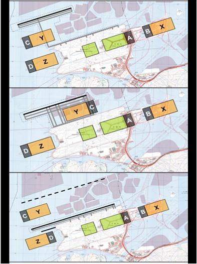
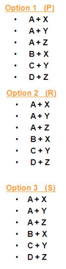
3.4.2.1
Based
on the three shortlisted runway alignment options identified, a total of 18
airport layout options were developed, covering all possible permutations of
apron, passenger terminal and concourse expansion locations. The 18 airport
layout options considered four possible locations for the new passenger
processing terminal (denoted as A, B, C, and D) and three possible locations for
the aircraft aprons and passenger concourse areas (denoted as X, Y, and Z) as
shown in Figure 3.1 (from
MP2030).
|
Figure 3.1: Eighteen
layout
options
|
|
LEGEND
A,
B, C & D show possible location of passenger processing
terminal (where passengers are processed for check-in,
Customs/Immigration/Quarantine and security screening)
X,
Y & Z show the possible location of aircraft apron and
passenger concourse area (where aircraft gates are located)
P,
R & S denote spacing between the third and existing North Runways (i.e. far-spaced, normal-spaced and close-spaced)
respectively
|
3.4.2.2
A qualitative review of the evaluation
criteria (shown in Table 3.3)
was then conducted by the MP2030 Study Consultant, to select better performing
airport layout representative(s) from each of the three shortlisted runway
alignment options (i.e. Option P, Option R and Option S) for carry forward to
the detailed evaluation stage.
Table 3.3: Criteria
for Initial Stage Airport Layout Options Evaluation
|
1.
|
AIRFIELD
|
|
|
|
- Taxiing
Time / Distance
|
Relative compared
to each option
|
|
|
- Runway
Crossings
|
Relative compared
to each option
|
|
|
- Additional
Control Tower
|
If needed for
operations or for blocked lines of sight
|
|
|
- Balance
East / West
|
-
|
|
|
- Cargo
Connectivity
|
Proximity of stands / access to cargo
|
|
2.
|
TERMINAL
|
|
|
|
- Passenger
Connectivity
|
Minimum transfer time, APM complexity and capacity
|
|
|
- Baggage
Connectivity
|
Connection time / connectivity
|
|
|
- Duplication
of Facilities
|
Terminal processor, retail, surface access
interchange, APM, etc.
|
|
|
- Synergy
with Airport Related Development (ARD)
|
Proximity
|
|
3.
|
SURFACE ACCESS
|
|
|
|
- Road
Access & Capacity
|
Extension of existing roads and capacity of new road
|
|
|
- Airport
Express Line (AEL)
|
Ability to extend existing line, or the need to
create a secondary bifurcation
|
|
|
- Cross
Boundary Transport Facilities
|
Ability to serve cross boundary air / surface transit
passengers via Coach, SkyPier and potentially the Hong Kong-Shenzhen Western
Express Line (WEL)
|
|
4.
|
LONG-TERM
CAPACITY / FLEXIBILITY
|
|
|
|
- Strategic
Consideration
|
Ability to meet demand growth beyond 2030
|
|
5.
|
CONSTRUCTIBILITY
/ COST
|
|
|
|
- Runway
/ Taxiways
|
Runway / taxiway length or area
|
|
|
- Construct
over Mud Pits
|
Cost (and possible lead time)
|
|
|
- Terminal
Processor
|
Expansion / Extension of Terminal 1 (T1) / Terminal 2
(T2), or land formation for a new terminal
|
|
|
- Surface
Access – Road / Rail
|
Short extension of existing versus major line
extensions / bifurcation
|
|
|
- Total Land Formation Area
|
Land take-up
|
|
|
- Operational
Impact
|
-
|
Source: Airport
Authority Hong Kong, Hong Kong
International Airport,
HKIA Master Plan 2030 Technical Report, July 2011, http://vps.hongkongairport.com/mp2030/TR_24May_Eng_Full.pdf
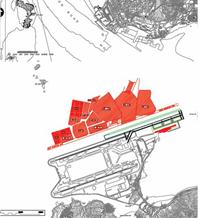
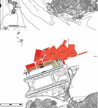
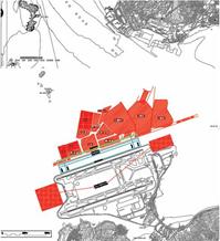
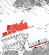
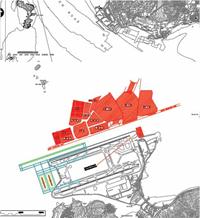
3.4.2.3
Four
airport layout options were shortlisted as a result of the qualitative review
as shown in Drawing Nos. MCL/P132/EIA/3-001 to
MCL/P132/EIA/3-004. The main characteristics of the shortlisted options
are summarised in Table
3.4.
Table 3.4: Summary of Shortlisted
Options
|
Shortlisted Option
|
Summary
|
|
Option P (A +
Y)
|
This
option adopts the original P runway alignment from NATS with a remote
satellite concourse to the northwest of the existing airport platform that is
connected to T2. The principal objective of this option is to avoid construction
over the CMPs and position passenger stands between a new widely spaced
parallel runway and the existing North
Runway.
|
|
Option R (A +
X)
|
This
option revises the original R runway alignment from NATS by shifting it as west
as practicable up to the Mainland territorial waters boundary, with a remote
linear satellite concourse north of the existing airport platform that is
connected to T2. The principal objective of this option is to minimise
construction over the CMPs and position passenger stands between a new widely
spaced parallel runway and the existing North Runway.
|
|
Option R (A +
Y)
|
This
option revises the original R runway alignment from NATS by shifting it
slightly to the east and north in order to fit in a remote satellite
concourse to the north of the existing airport platform, assuming
construction over the CMPs is feasible. The principal objective of this
option is to position passenger stands between a new widely spaced parallel
runway and the existing North
Runway that is connected
nearer to T2 as compared to
Option R (A+X)
|
|
Option S (D +
Z)
|
This
option adopts the original S runway alignment from NATS with a new passenger
terminal and concourse at the western end of the airport platform as the close
spacing between the third runway and the existing North Runway
would not allow for new facilities to be built in between. The principal
objective of this option is to avoid construction over the CMPs and position
a new passenger terminal and passenger stands to the west of existing airport
platform. The length of the new
runway is almost twice that of the P and R runway layout options to meet
flight procedure and safety requirements in operating the new runway and the
existing North Runway independently under a close-spaced arrangement.
|
3.4.2.4 The final stage of evaluation of the shortlisted
airport layout options
comprised an in-depth evaluation across key operational and functional parameters
collectively called “Non-Environmental Evaluation” as well as an engineering feasibility and
qualitative environmental assessment to identify an overall preferred option.
3.4.3.1
Based
on new land requirements for siting infrastructure required for the 3RS, the four
shortlisted airport layout options could be generally categorised
into two categories of
options, namely “Northward Expansion” and “Westward Expansion”.
An in-depth assessment of relative
performance across key operational and functional parameters
was undertaken for Northward and Westward expansion options.
Westward Expansion - Option
S (D+Z)
¡ The third runway adopts a close-spaced separation from the existing North Runway, with new operational infrastructure required to support the 3RS to be located on
land formation to the west of the existing airport island.
Northward
Expansion - Option P (A + Y), Option R (A + X) and Option R (A + Y)
¡ The third runway adopts a wide-spaced separation from the existing North Runway, with additional operational infrastructure required to support
the 3RS to be sited on land formation to the north of the existing airport
island.
The outcome of
the non-environmental relative performance evaluation of the two families of
airport expansion options, as set out in MP2030, is recapped in
Table 3.5.
Table 3.5: Comparative Performance Between Two Airport Expansion Options
|
Criteria
|
Westward
Expansion
|
Northward
Expansion
|
|
Airfield Efficiency
|
O
|
P
|
|
Passenger Convenience
|
O
|
P
|
|
Surface Access
|
O
|
P
|
|
Cargo Operations Efficiency
|
O
|
P
|
Note: where the criteria are met, this is denoted by ‘P ‘. Where the criteria is not met, this is
denoted by ‘O ‘.
Source: Airport
Authority Hong Kong, Hong Kong International Airport, HKIA Master Plan 2030
Technical Report, July 2011, http://vps.hongkongairport.com/mp2030/TR_24May_Eng_Full.pdf
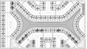
3.4.3.2
A summary of the comparison between the Westward expansion
option relative to the Northward expansion option is as follows:
Airfield
Efficiency
a)
For
close-spaced parallel runways to be able to maintain independent segregated
operations under ICAO guidelines, it is necessary to extend the third runway
length from 3,800 m to 6,750 m, and the second runway
(i.e. existing North Runway) length by 950 m to the
west so that a 1,950 m stagger towards
the arriving aircraft is available for both runway directions 07 and 25 (see Figure 3.2).
|
Figure 3.2: Illustration of runway extension required under a close-spaced parallel runway arrangement
|
|
This entails a
substantial additional land formation area for the third runway as compared to the Northward expansion option, which has sufficient runway separation to adopt
a normal length of 3,800 m for the third runway.
b)
The
separation of the close-spaced third runway from the first
runway (i.e. existing South Runway) is also not sufficient to support
independent parallel approaches. Only dependent staggered approaches can be
accepted which will reduce the overall capacity of the 3RS to 97 movements per hour as compared to
102 under the Northward expansion option supporting independent parallel
approaches (see Table 3.6).
Table 3.6: Runway Capacity of the Westward
Expansion Option
|
Runway
|
Use
|
Capacity
|
Arrivals
|
Departures
|
|
07L/25R
|
Arrivals
|
31
|
31
|
─
|
|
07C/25C
|
Departures
|
35
|
─
|
35
|
|
07R/25L
|
Mixed
|
31
|
15.5
|
15.5
|
|
Total
|
─
|
97
|
46.5
|
50.5
|
Note: Values refer to the number of aircraft movements per
hour.
Source: Airport
Authority Hong Kong, Hong Kong International Airport, HKIA Master Plan 2030 Technical
Report, July 2011, http://vps.hongkongairport.com/mp2030/TR_24May_Eng_Full.pdf
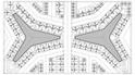
c)
The
close-spaced third
runway does not allow room
for locating the additional passenger aircraft stands requirement adjacent to
the third
runway as compared to the
Northward expansion option. Aircraft arriving on the third runway need to taxi across the existing airfield to the apron on the western land formation or Midfield area, creating longer taxiing
time, increased ground congestion and delays, and more
runway crossings than the Northward expansion
option which will likely further reduce
runway capacity to less than 97 movements per hour (see Figure 3.3).
|
Figure 3.3: Aircraft
ground
movements
congestion
under the Westward
expansion
options
|
|
Passenger Convenience
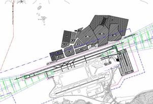
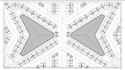
3.4.3.3
The Westward expansion option for developing a new passenger
processing terminal (Terminal 3 or T3) and a new passenger concourse at the
western side of the airport island would require passengers to make an early
decision when approaching T1, T2 or T3 (i.e. boarding public transport routes
bound for T1 / T2 versus a separate route bound for T3). Due to the large
distance separation between T3 and T1/ T2, an accommodation for route recovery
would be require in the event when passengers proceed to the wrong terminal.
There would also be added inconvenience and longer travelling distances for
inter-terminal transfers and inter-modal connections with Hong Kong - Zhuhai -
Macao Bridge (HZMB) (see Figure 3.4)
and SkyPier located on the eastern side of the airport island.
|
Figure 3.4: Passenger
inconvenience
of the Westward expansion
options
|
|
3.4.3.4
The Northward expansion option for the development of
the new passenger concourses would lessen passenger inconvenience associated with
the Westward expansion option. The Northward expansion option would have
passengers from the new concourses processed through the existing passenger
terminal zone via expansion of the existing T2 into a full-fledged departures
and arrivals terminal with dedicated underground APM and BHS linked to the new
passenger concourses.
Surface Access Quality
3.4.3.5
The
Westward expansion option cannot share the existing fully integrated ground
transportation facilities already established at the eastern side of the airport
island, particularly the direct connections to the AEL
station to downtown and the APM station to the SkyPier ferry terminal and
future Hong Kong Boundary Crossing Facilities (HKBCF) (see Figure 3.5). The split passenger terminal zones
associated with the Westward expansion option would inevitably lead to inferior
surface access quality compared to that of a centralised passenger processing
terminal zone that is provided for under the Northward expansion option.
Figure 3.5: AEL and SkyPier ferry terminal
Cargo Operations Efficiency
3.4.3.6
Given
that cargo transport is time-critical, it is preferred to locate the new
freighter stands at the Midfield to allow shorter towing distances between the
new freighter stands and the cargo terminals in the southern cargo precinct (see
Figure 3.6). This
could only be achieved under the Northward expansion option but not the
Westward expansion option which needs to assign the entire Midfield area for
new passenger concourses development to minimise taxiing distance to/from
passenger aircraft stands.
|
Figure 3.6: Preferred location of future cargo apron and freighter stands
|
|
|
3.4.3.7
The non-environmental evaluation has identified that “Northward
Expansion” is preferred to “Westward Expansion” in enlarging the footprint of
HKIA into a 3RS. The outcome
of the non-environmental evaluation was supported by the “Engineering
Feasibility and Environmental Assessment Study for Airport Master Plan 2030, Comparative
Environmental Assessment” with
Option R (A + Y) within
the Northward expansion family options also being identified as the best environmental performing option,
which was consequently adopted by MP2030 for development into the recommended
layout for the 3RS
scenario.
3.4.4.1
The
environmental evaluation was undertaken in parallel with the non-environmental
evaluation and forms part of the assessments in the Engineering Feasibility and Environmental Assessment Study for Airport
Master Plan 2030, Comparative Environmental Assessment Report completed in
2009 by Mott MacDonald [5].
Early Consideration of
Environmental Implications associated with Engineering Design
3.4.4.2
The
main potential environmental implications of a third runway result primarily
from both the physical location / footprint of the airport expansion and
construction methods that are developed for land formation. Thus, engineering
design considerations and requirements do have significant impacts on the environmental
performance of different airport layout options. Table
3.7
shows the major land formation characteristics
associated with each shortlisted option.
Table 3.7: Summary of the Major Characteristics
of Each Shortlisted
Option [5]
|
Major Characteristics
|
P (A + Y)
|
R (A + X)
|
R (A + Y)
|
S (D + Z)
|
|
Total land formation area
|
743 ha
|
790 ha
|
827 ha
|
819 ha
|
|
Encroachment to CMPs
|
3 ha
|
32 ha
|
200 ha
|
Nil
|
|
Seawall length
|
18 km
|
18 km
|
11 km
|
15 km
|
|
Minimum clearance to Chinese Territorial Waters
boundary
|
150 m
|
100 m
|
1 km
|
1 km
|
|
Minimum clearance to Sha Chau and Lung Kwu Chau Marine
Park
|
350 m
|
1 km
|
1 km
|
2 km
|
Identification of the Key Environmental
Differentiators for Comparison of Options
3.4.4.3
A
set of environmental performance indicators was developed to facilitate a
simple ‘option to option’ comparison of the key anticipated environmental
impacts, at construction and operation stages.
The comparison exercise was not intended to be a thorough “quantitative”
assessment of environmental impacts and their acceptability, rather, a simple
differentiation of the shortlisted options based on “larger” or “smaller”
impact in the indicator area for each of the options – allowing for a simple
ranking of options3. The key environmental
differentiators adopted for shortlisted airport layout options evaluation are
presented in Table
3.8.
3
Environmental differentiators are those environmental parameters assessed as
exhibiting potential variability between options. Certain environmental
parameters, such as construction phase air quality impact, were not included as
they were assessed as exhibiting no significant variability between options.
Table 3.8: Summary of Key Environmental
Differentiators During Construction
and Operation Phase [5]
|
Key Environmental Differentiators
|
Construction
Phase
|
Operation
Phase
|
|
Air Quality
|
N/A
|
§
Airport operational efficiency1
|
|
Chinese White Dolphins (CWD)
|
§
Disturbance to CWD feeding grounds
§
Disturbance to dolphin calves
|
§
Permanent loss of feeding grounds
§
Proximity of northern site boundary to Sha
Chau and Lung Kwu Chau Marine Park
(and associated risk of CWD injury due to collision with vessels)
|
|
Fisheries
|
§
Disturbance to fisheries production
§
Disturbance to fishing operation
§
Loss in fisheries value due to construction
|
§
Permanent loss in fisheries production
§
Habitat loss
§
Fishing operation
§
Fisheries value
§
Impact of Hong Kong International Airport Approach Area
(HKIAAA) on fisheries operation
|
|
Marine Ecology
|
§
Disturbance to horseshoe crab nursery grounds
§
Impact of increased suspended solids (SS)
concentrations on marine ecological sensitive receivers
§
Disturbance to existing coral and artificial
reefs
|
§
Loss of intertidal habitats
§
Loss of soft-bottom habitats
§
Loss of coral communities
|
|
Noise
|
§
Cumulative impact due to concurrent projects
on noise sensitive receivers (NSRs)
|
§
No. of dwellings situated within a preliminary
noise exposure forecast (NEF) 25 contour projection
|
|
Visual
|
§
Disturbance to visually sensitive receivers
(VSRs) at Sha Lo Wan and Tung Chung
|
§
Disturbance to VSRs at Sha Lo Wan and Tung
Chung
|
|
Waste
|
§
Quantity of dredged sediment (outside of CMPs)
|
N/A
|
|
Water Quality and Hydrodynamics
|
§
Increase in SS concentrations at water
sensitive receivers
§
Release of sediment fines and contaminants
during ground improvement at CMPs
|
§
Change in tidal flow
§
Erosion of seabed
§
Change in flushing capacity at the existing airport channel
§
Potential water quality impact from a poorly
flushed embayment
|
Note 1: This provides a measure of the potential operation phase air
quality as it relates to aircraft emissions.
3.4.4.4
Other
environmental parameters, such as construction phase air quality impact, hazard to life, terrestrial ecology,
landscape and cultural heritage, were identified as not being significant differentiators that
could be used in the options evaluation and hence were excluded from the
options selection process.
Environmental Evaluation of the Shortlisted
Options – Benefits
and Dis-Benefits
3.4.4.5
For
the differentiators identified under each key environmental aspect, relative
environmental performance was summarised into an equivalent relative ranking
for each shortlisted option. The
ranking evaluation was made based on best professional judgement of the information available at the time
of evaluation, giving
more focus on key long-term and irreversible environmental impacts. A summary
of findings from the comparative environmental assessment is presented in Table
3.9.
Table 3.9: Summary of Environmental
Evaluation
of the Shortlisted Options [5]
|
Key Environmental Differentiators
|
Option
1 – P (A + Y)
|
Option
2 – R (A + X)
|
Option
3 – R (A + Y)
|
Option
4 – S (D + Z)
|
Preferred
Option
|
|
|
Environmental
Benefit
|
Environmental
Dis-benefit
|
Environmental
Benefit
|
Environmental
Dis-benefit
|
Environmental
Benefit
|
Environmental
Dis-benefit
|
Environmental
Benefit
|
Environmental
Dis-benefit
|
|
|
Air Quality
|
·
No defining benefit compared to other options
|
·
No defining benefit compared to other options
|
·
No defining benefit compared to other options
|
·
No defining benefit compared to other options
|
·
No defining benefit compared to other options
|
·
No defining benefit compared to other options
|
·
No defining benefit compared to other options
|
·
Generally associated with less operational
efficiency compared to other options.
|
No
definitive option is preferred.
|
|
CWD
|
·
Affect a smaller area associated with CWD calves
sighting, therefore has lower
potential to adversely impact CWD breeding grounds.
·
Smallest
area of permanent habitat loss and a smaller number of CWDs potentially affected.
|
·
Affect a larger area associated with CWDs engaged
in socialising activities, therefore has higher potential to adversely affect CWD
social activities (along with Option 2).
·
Located closest to the Sha Chau and Lung Kwu
Chau (SCLKC)
Marine Park, therefore has higher potential
disturbance to CWD protected area.
·
Evaluated
to have higher
potential severity of impacts to CWDs during operation phase
|
·
Affect a smaller area associated with CWDs engaged in feeding activities, therefore
has lower
potential for disturbance to feeding grounds (along with Option 3).
|
·
Affect a larger area associated with CWDs engaged
in socialising activities, therefore has higher potential to adversely affect CWD
social activities (along with Option 1).
|
·
Affect a smaller area associated with CWDs engaged in feeding activities, therefore
has lower
potential for disturbance to feeding grounds (along with Option 2).
|
·
Largest
area of habitat loss (but the lost habitat was less used by CWDs)
|
·
Affect a smaller area associated with CWDs engaged
in socialising activities, therefore has lower potential to adversely affect
CWD social activities.
·
Located furthest from the SCLKC Marine Park, therefore has lower potential disturbance to CWD
protected area.
|
·
Affect a larger area associated with CWD calves
sighting, therefore has higher
potential to adversely impact CWD breeding grounds.
·
Affect a larger area associated with CWDs engaged in feeding activities, therefore
has higher
potential for disturbance to feeding grounds.
·
Larger
area of permanent habitat loss and number of CWDs potentially affected.
·
Evaluated
to have higher
potential severity of impacts to CWDs during both construction and operation
phase.
|
Option 3 – generally associated with
less CWD impacts compared to the other options.
|
|
Fisheries
|
·
Smallest area of potential fisheries habitat
loss
|
·
Future HKIAAA may extend outside Hong Kong
marine waters boundary and would lie closest to the SCLKC Marine Park, which may
discourage fishing activities in this area.
|
·
No defining benefit compared to other options
|
·
Future HKIAAA may extend outside Hong Kong
marine waters boundary and make access to the high fisheries production areas
at northwest Lantau difficult for fishermen.
|
·
Relatively less potential impact to fisheries
activities due to wider separation between the new HKIAAA, SCLKC Marine Park and Hong Kong
marine waters boundary.
|
·
Largest area of potential fisheries habitat
loss
|
·
No defining benefit compared to other options
|
·
Future HKIAAA may discourage fishermen from
fishing at northwest Lantau.
|
Option 3 – generally considered to
have marginally less impact on fisheries activities compared to other
options.
|
|
Marine Ecology
|
·
No defining benefit compared to other options
|
·
Located
closest to the SCLKC
Marine Park, therefore is associated with higher potential impact on the Marine Park due to SS
release during construction phase.
|
·
No defining benefit compared to other options
|
·
No defining dis-benefit compared to other
options
|
·
Located
furthest from the
Sha Lo Wan horseshoe crab habitat, therefore is associated with less potential impact on the habitat due to SS release
during construction phase.
|
·
No defining dis-benefit compared to other
options
|
·
Located
furthest from the SCLKC
Marine Park, therefore is associated with less potential impact on the Marine Park due to SS release
during construction phase.
|
·
Located
closest to the Sha Lo Wan horseshoe crab habitat,
therefore is associated with higher potential impact due to SS
release during construction phase.
|
Option 3 – associated with less
dis-benefits compared to Options 1 and 4, and more benefits compared to
Option 2.
|
|
Noise
|
·
Potentially associated with less aircraft
noise impacts to NSRs (due to larger runway separation distance).
|
·
No defining dis-benefit compared to other
options
|
·
No defining benefit compared to other options
|
·
No defining dis-benefit compared to other
options
|
·
Further separation distances from NSRs along North Lantau.
·
Potentially associated with less aircraft
noise impacts to NSRs (due to larger runway separation distance).
|
·
No defining dis-benefit compared to other
options
|
·
No defining benefit compared to other options
|
·
Shorter separation distances from NSRs along North Lantau.
·
Potentially associated with more aircraft
noise impacts to NSRs
|
Option 3 – generally associated with
more benefits compared to other options.
|
|
Landscape & Visual
|
·
Relatively further from VSRs at Tung Chung
|
·
Relatively closer to VSRs at Sha Lo Wan
|
·
Relatively further from VSRs at Tung Chung
|
·
Relatively closer to VSRs at Sha Lo Wan
|
·
Generally further from VSRs at both Sha Lo Wan
and Tung Chung
|
·
No defining dis-benefit compared to other
options
|
·
No defining benefit compared to other options
|
·
Closest to VSRs at Sha Lo Wan
|
Option 3 – generally associated with
less dis-benefits compared to other options.
|
|
Water Quality and Hydrodynamics
|
·
No defining benefit compared to other options
|
·
Relatively higher SS concentration at some water sensitive receivers (WSRs) compared to other options.
·
Re-deposition of sediment on corals is highest
compared to other options
·
Area of stagnant water produced due to eastern
embayment
·
Highest erosion potential around the new
runway
|
·
Lower SS concentration at some WSRs compared
to other options.
|
·
Area of stagnant water produced due to eastern
embayment
|
·
Generally lower SS concentration at WSRs
compared to other options.
·
Not associated with significant flow
stagnation.
|
·
No defining dis-benefit compared to other
options
|
·
Relatively lower SS concentration at some WSRs
compared to other options.
·
Not associated with significant flow
stagnation.
|
·
Relatively higher SS concentration at some
WSRs compared to other options.
·
Reduce flushing capacity at Airport Channel
·
Higher siltation potential at Airport Channel
than other options
|
Option 3 – generally associated with
less water quality impacts compared to the other options.
|
|
Cultural Heritage
|
Not
a key environmental differentiator as all options would have similar potential marine
archaeological impact, and no direct impacts to terrestrial cultural
heritage.
|
|
Hazard to Human Life
|
Not
a key environmental differentiator as all options would have similar potential hazard to human
life impacts
associated with diversion of submarine fuel pipeline, extension of fuel
hydrant system, and dangerous goods storage (diesel, gasoline and liquid
petroleum gas).
|
|
Terrestrial Ecology
|
Not
a key environmental differentiator as all options would have similar impacts (mainly
indirect impacts) to terrestrial ecology.
|
|
Waste*
|
·
Lowest quantity of dredged sediment (outside
CMP area)
|
·
No defining dis-benefit compared to other
options
|
·
No defining benefit compared to other options
|
·
No defining dis-benefit compared to other
options
|
·
Lowest quantity of
dredged sediment requiring disposal (outside CMP area)
|
·
No defining dis-benefit compared to other
options
|
·
No defining benefit compared to other options
|
·
Highest quantity of dredged sediment requiring
disposal (outside CMP area)
|
No longer applicable
|
Note:
The evaluation was based on the findings of the “Contract P132 – Engineering
Feasibility and Environmental Assessment Study for Airport Master Plan 2030,
Comparative Environmental Assessment Report”, (Deliverable D1.8), May 2009,
Mott MacDonald Hong Kong Limited ( http://vps.hongkongairport.com/mp2030/consultancy_report/Mott_1.pdf), which was compiled according to the
information available at the time of preparing that report.
*
The waste differentiator was based on previous assumptions of using dredged
land formation. As the project is now confirmed to use non-dredge methods, this
key differentiator is no longer applicable (but it is nevertheless presented
for completeness).
3.4.4.6
The
findings of the comparative environmental evaluation identified Option 3 as
performing relatively better than the other options with respect to the
majority of environmental differentiators.
3.4.5.1
The
results of both non-environmental and environmental evaluations concluded that
Option 3 – R (A + Y) is the best performing option of those shortlisted. Option
3 – R (A + Y) was also recommended as the preferred three-runway MP2030 layout.
3.4.6.1
Some
possible refinements to the shortlisted options were analysed as part of the Engineering Feasibility and Environmental
Assessment Study for Airport Master Plan 2030, Comparative Environmental
Assessment Report [5] to facilitate further development of the layout with
a view to enhancing their environmental performance. Table
3.10
summarises the further environmental refinements that
were considered.
Table 3.10: Summary of Possible Refinements and Environmental Benefits
/ Dis-benefits
[5]
|
Option
|
Possible
Refinement
|
Environmental
Benefits / Dis-benefits of Refinement
|
|
Option 1 – P (A + Y)
|
Maximise
the distance from the SCLKC Marine
Park
|
This
seeks to increase the distance from the SCLKC Marine Park from 350 m to 700 m by reducing the
northern extent of land formation. However, this option would still be closer
to the Marine Park than the other options,
hence no significant change to the environmental impact levels and relative
ranking is anticipated.
|
|
Reducing
the extent of land formation at the western side of the existing North Runway
|
The possibility of reducing the extent of land
formation at the western side would lead to improvements in terms of:
§
reduced disturbance to CWD feeding grounds and
calves;
§
reduced loss of soft-bottom habitats and coral
communities; and
§
reduced quantity of dredged sediment
However,
the creation of a poorly flushed embayment would increase the potential water
quality and hydrodynamic impact for this option.
|
|
Option 2 – R (A + X)
|
Reducing
the extent of land formation and use of decking for the taxiway
|
This
seeks to significantly reduce the extent of land formation and eliminate the
poorly flushed embayment by using decking instead of land formation for the
taxiway. Improvements include:
§
improved flushing capacity;
§
reduced disturbance to fisheries production;
§
reduced loss of intertidal habitats and
soft-bottom habitats;
§
reduced impact of increased SS on marine ecological sensitive
receivers; and
§
reduced quantity of
dredged sediment.
However,
as piling would be required for construction of the decking, the impact on
CWDs would increase.
|
|
Eliminating
the embayed area
|
This
seeks to possibly eliminate the embayed area by shifting the proposed runway
to the south. This would lead to improvements in terms of:
§
reduced impact to CWDs due to greater
separation distance from the Marine
Park and less habitat
loss; and
§
reduced embayment
areas.
|
|
Option 3 – R (A + Y)
|
Reducing
the extent of land formation at the western side
|
The possibility of reducing the extent of land
formation at the western side would lead to improvements in terms of:
§
reduced permanent loss of CWD feeding grounds;
§
reduced impact on fisheries production and
operation;
§
reduced loss of intertidal, soft-bottom and
coral communities / habitats;
§
less disturbance to horseshoe crab nursery
grounds; and
§
reduced quantity of
dredged sediment.
|
|
Shifting
the proposed runway to the east
|
This seeks to give a more streamlined footprint
from a hydrodynamic point of view, however, the findings of the hydrodynamic
assessment found that no significant change in tidal flow was predicted, and
no significant improvement in terms of erosion of the seabed was predicted.
Consequently, no additional environmental benefit was identified with this
refinement.
|
|
Option 4 – S (D + Z)
|
Eliminating
the embayed area
|
This
seeks to create a more streamlined footprint by trimming the eastern end of
the proposed runway to eliminate the embayed area. This would lead to
improvements in terms of:
§
removal of the poorly flushed embayment;
§
reduced impact to CWDs by reducing habitat
loss and disturbance to feeding grounds and dolphin calves;
§
reduced habitat loss and impact on fisheries
production;
§
reduced loss of soft-bottom habitats and
reduced disturbance to artificial reef and impact from SS; and
§
reduced quantity of
dredged sediment.
|
|
Reducing
the extent of land formation by use of decking for taxiway near the airport sea channel
|
This
refinement seeks to minimise hydrodynamic impact by eliminating about 24 ha
of land formation by using decking for the taxiway. This would lead to
improvements in terms of:
§
reduced impact on the flushing capacity at the
channel;
§
reduced loss of soft-bottom habitats and less
disturbance to horseshoe crab nursery grounds; and
§
reduced quantity of
dredged sediment.
However,
as piling would be required for construction of the decking, the impact on
CWDs would increase.
|
|
Trimming
of headland around Sha Lo Wan
|
This
seeks to improve the flushing capacity at the airport sea channel, but would result in permanent loss of
habitats for horseshoe crabs.
|
Source: Based
on Airport Authority Hong Kong, Hong Kong International Airport, Contract P132
– Engineering Feasibility and Environmental Assessment Study for Airport Master
Plan 2030, Comparative Environmental Assessment Report, (Deliverable D1.8), May
2009, Mott MacDonald Hong Kong Limited, http://vps.hongkongairport.com/mp2030/consultancy_report/Mott_1.pdf
3.4.6.2
The
possible refinements considered in Table
3.10
were used to re-evaluate the options and the findings showed that refinements did not result in any
change to the fundamental environmental performance of shortlisted options, confirming Option 3 – R (A + Y) as the
preferred option to take forward.
3.4.6.3
Taking
into account the environmental benefits identified in Table
3.10,
the preferred Option 3 was revised accordingly and the improved preferred
option is shown in Drawing No. MCL/P132/EIA/3-005.
3.5.1.1
With
a preferred option selected, it was possible to explore in greater detail
specific operational issues and to further refine individual components to
maximise operational efficiency, particularly airside access and integration of
existing airport operations. The most significant changes included:
¡ Minor reshaping of the eastern edge of the new land formation; and
¡ Introduction of ‘wrap-around’ taxiways to minimise runway
‘crossing’ to enhance operational safety for aircraft crossing the future
‘centre’ runway.
3.5.1.2
These
changes were primarily due to operational requirements, and given that the
modified layout remains conceptually similar to the preferred option, the
environmental performance of this modified layout is expected to be consistent
with the preferred option.
3.5.2.1
As
part of the initial scheme design for the project, a number of concourse layout
options were considered and evaluated. Table
3.11
presents a summary of the TRC options that were
considered for the 3RS.
Table 3.11: Summary
of Third Runway Concourse Options
|
|
Option 1
BASELINE
|
Option 2
TRIPLE CONCOURSES
|
Option 3
Y-Y
|
Option 4
TWIN - STAR
|
Option 5
TWIN - TRIANGLE
|
Option 6
HORSESHOE
|
Preferred Option
|
|
General Description
|
|

|
|
|
|

|
|
|
|
Based on the
existing T1, the Baseline scheme adopts the same T1 concourse width with the
baggage hall located underground.
|
Based on the
MP2030 layout. This scheme adopts three separate concourses with the baggage
hall located underground.
|
Single concourse
layout derived from the Baseline scheme, with wider concourse to accommodate
baggage hall at apron level.
|
Based on the
Baseline scheme but with an expanded area within the concourse to create
additional reserve areas and accommodate baggage hall at apron level.
|
Similar to the
Twin Star scheme with larger reserved area at each concourse for future
expansion and accommodate baggage hall at apron level.
|
This scheme
represents the ultimate shape that provides the largest area to perimeter
ratio. The aim of this configuration
is to maximise the area available for reserve land for future expansion and
accommodate baggage hall at apron level.
|
N/A
|
|
Capacity
|
62 contact stands
47 remote stands
|
60 contact stands
40 remote stands
|
60 contact stands
45 remote stands
|
62 contact stands
36 remote stands
|
62 contact stands
42 remote stands
|
54 contact stands
25 remote stands
|
Option 1 or 3
|
|
Operational Efficiency
|
This option has
high taxiway efficiency and user friendliness with easy route recovery and
transfers between the concourse, but has limited
space for passenger / commercial facilities.
|
This option presents
a risk of taxiing congestion and increased airside road journey times between
the two farthest nodes, though it has the benefit of providing taxi-lane
alternatives and shorter taxiing distance for certain stands.
In terms of
terminal operations, more concourses complicate passenger wayfinding and the
additional facilities required (e.g. three APM stations and separate baggage
systems) would increase both journey / transit times and operational costs.
This option is the
least efficient overall.
|
This option
provides greater operational efficiency and user friendliness with easy route
recovery and transfers between the concourse and better space allocation to
accommodate different passenger / commercial facilities.
Baggage
operational efficiency is generally higher than other configurations.
|
Similar efficiency
to the Baseline scheme and provides shorter taxiing distance for certain
stands, but concourse operational efficiency is affected by the split
concourses, which necessitates some duplication of facilities.
|
Similar efficiency
to the Baseline scheme, but concourse operational efficiency is affected by
the split concourses, which necessitates some duplication of facilities.
|
This option has
poor taxiway efficiency due to uni-directional taxi-lane layout.
Concourse
operational efficiency is also affected by the split and uneven concourses.
|
Option 3
|
|
Phasing / Flexibility
|
Single concourse
enables consolidation of terminal facilities and provides more flexibility
for phased commissioning.
Limited
opportunity for creating outdoor spaces.
No reserve area
for future expansion.
|
Based on capacity
requirements, at least two of the three buildings will need to be
commissioned in Phase 1.
Limited opportunity
for creating outdoor spaces.
No reserve area
for future expansion.
|
Single concourse
enables consolidation of terminal facilities and provides more flexibility
for phased commissioning.
Opportunities
available for creating outdoor spaces which can be safeguarded for future
expansion.
|
Large central
concourse area allows for future expansion flexibility, but less capacity for
phased commissioning of facilities.
|
Large central
concourse area allows for future expansion flexibility, but less capacity for
phased commissioning of facilities.
|
Large central
concourse area allows for future expansion flexibility, but less capacity for
phased commissioning of facilities.
|
Option 3
|
|
Programme and Costs
|
No significant difference
in construction programme compared to other options.
|
No significant
difference in construction programme compared to other options.
Higher
construction cost due to multiple terminal buildings and associated APM / BHS
facilities.
|
No significant
difference in construction programme compared to other options.
Cost for the wider
concourse is offset by the bag hall at apron level.
|
No significant
difference in construction programme compared to other options.
Generally higher
construction cost due to larger building area.
|
No significant
difference in construction programme compared to other options.
Generally higher
construction cost due to larger building area.
|
No significant
difference in construction programme compared to other options.
Generally higher
construction cost due to larger building area.
|
Option 1 or 3
|
|
Environmental
|
Requires
excavation into CMPs
|
Requires
excavation into CMPs
|
Avoids the need
for excavation into CMPs
|
Avoids the need
for excavation into CMPs
|
Avoids the need
for excavation into CMPs
|
Avoids the need
for excavation into CMPs
|
Option 3 to 6
|
Environmental
Benefits / Dis-Benefits
3.5.2.2
In
general, the only environmentally significant consideration between different
TRC configuration options is whether excavation into the CMPs is required or
not, which would affect the quantities of excavated marine sediment. Apart from
this aspect, the various TRC options do not have a significant bearing on the
environmental acceptability of the project, as there are no other significant
environmental differences among the TRC options. Based on this environmental consideration, Options
3 to 6 would be equally more preferable from an environmental perspective when
compared to Options 1 and 2.
3.5.2.3
Given
that there are limited environmental differences between options, the decision
for selection of the preferred scenario for TRC configuration is thus dominated
by capacity and operational considerations. However, in selecting the TRC
option that provides the best overall operational and efficiency gains, there
are inherent environmental benefits resulting from these efficiency gains, such
as reduced raw materials requirement during construction phase, and reduced
building energy consumption during operation phase. Similar ‘environmental
dis-benefits’ would apply to options that are less operationally efficient.
Selection
of Preferred Scenario – Third Runway Concourse
3.5.2.4
Based on the comparison of TRC options as
shown in Table
3.11, the single
concourse Y-Y configuration (Option 3) has been identified and selected as the
preferred scenario for the 3RS.
In a similar manner to the existing T1, the single concourse configuration is
considered to offer important operational benefits including:
¡ Ground vehicle movements not impeded by having to cross cut through
taxi lane;
¡ Single baggage hall at apron level to allow efficient baggage ramp
handling and reducing tug and dolly travel distances;
¡ Flexibility to allocate aircraft to stands and increased efficiency
in terms of staffing / resource allocation;
¡ Requires fewer ground service equipment (GSE) to service aircraft
as vehicles do not need to be allocated to separate terminals;
¡ Can be built incrementally, which provides flexibility in planning
and phasing; and
¡ Flexibility in terms of catering to future demands, i.e. airline
allocation.
3.5.2.5
Accordingly, the preferred scenario would
provide environmental benefits in terms of:
¡ Avoidance of excavation into CMPs and less waste generated due to
excavation;
¡ Reduced GSE emissions (due to few GSE and more efficient vehicle
movements); and
¡ Less building energy demand (due to improved operational
efficiency).
3.5.3.1
As an outcome of the airport layout options assessment, the
existing T2 will be partly demolished, modified extensively and expanded to become
a full-fledged passenger processing terminal to serve the new third runway. Two
options for T2 expansion and associated road network were considered and
evaluated. Table
3.12
presents a summary of these options and the road
network options are shown in Drawing No. MCL/P132/EIA/3-008.
Table 3.12: Summary of Descriptions and Construction Methods for Terminal 2
Expansion and the Associated Road Networks Options
|
Parameters
|
Terminal
Concept A
|
Terminal
Concept F
|
|
General Design
|
Terminal:
This option assumes
that T2 has to be partially shut down and modified in order to expand to the
new terminal layout, while keeping operation in T2 throughout the entire
construction period. Facilities of the expanded T2 include the main building
composed of Departures Hall, Check-in Hall, Departures Kerb, Baggage Claim
Hall, Meeters and Greeters Hall, Custom, Immigration and Quarantine (CIQ)
Area, Baggage Handling Area, APM Interchange Station and BHS North Basement,
and the North and South Annex Buildings accommodating coach staging, car
parking, loading and unloading, and limousine lounge provisions. As the
Departures Kerb is positioned on the eastern side of the main building,
bi-directional passenger flows from new Departures Kerb and existing AEL
Station to Check-in Hall at Departures Level are anticipated.
Associated Road
Networks Option A1:
The departures
kerb of this option is located at the eastern side of the terminal. This road option provides a longer length
of departures kerb comparing to Option A2 below. A slip road linking the northern elevated
road to existing Airport Road is proposed for recirculation to T1 departures
kerb. Slip roads connecting to North Lantau Highway (NLH)/Airport Road and
HKBCF are also allocated at the south of the CLP substation.
Based on this
configuration, the proposed northern elevated road and realigned SkyCity Road
will encroach onto the North Commercial District (NCD) development area and
the AsiaWorld Expo (AWE)
Phase 2 Expansion site.
Associated Road
Networks Option A2:
The departures
kerb of this option is located at the eastern side of the terminal. To minimise the encroachment into AWE Phase
2 Expansion Area, a “ring road” option is developed with the elevated road
for egress traffic from the T2 departures kerb to circulate around the NCD
development site along its northern and eastern perimeter and connect back to
Airport Road southbound south of the airport
south interchange. Separate
slip roads for re-circulation / route recovery to T2 departures kerb and
connection to HKBCF are branched off from the elevated road at the eastern
perimeter. The length of the departures kerb in this option is shorter than
Option A1 by about 60 m.
This road option
does not have major impact to existing building structures but will confine
the NCD development within the boundary of the elevated ‘ring’ roads.
|
Terminal:
This option
assumes that the operation in T2 will be suspended during the entire
construction period as T2 has to be shut down and substantially modified in
order to add a new floor, raise the roof, build the new Departures Road on
the western side of the main building, and increase pile loading capacity
etc. Facilities of the expanded T2 include the main building composed of
Departures Hall, Check-in Hall, Departures Kerb, Baggage Claim Hall, Meeters
and Greeters Hall, CIQ Area, Baggage Handling Area, APM Interchange Station
and BHS North Basement, and the North and South Annex Buildings accommodating
coach staging, car parking, loading and unloading, and limousine lounge provisions.
As the Departures Kerb is positioned on the western side of the main
building, unidirectional passenger flows from new Departures Kerb and
existing AEL Station to Check-in Hall at Departures Level can be achieved.
Associated Road
Networks Option F:
This option
assumes the location of the departures kerb to be positioned on the western
side of the building immediately east of the existing HKIA Tower and Airport
World Trade Centre (AWTC), which will require demolition of Level 5 slab of
the existing T2 building. Under this option, two elevated roads connected to
northern and southern ends of the proposed departures kerb were proposed for
vehicle re-circulation to T2 departures kerb. The southern recirculation ramp
and the approach ramp linking to HKBCF will route along the western and
southern sides of existing CLP Primary Substation. The length of departures
kerb in this option is similar to Option A1. With departures kerb on the
western side of the terminal building, unidirectional check-in experience for
departures passengers, similar to T1, can be achieved.
This road network
option can avoid major encroachment on adjacent commercial development sites.
In comparison with
Options A1 and A2, Option F is considered to be a better option in terms of
terminal planning and has less impact on future adjacent commercial
developments.
|
|
Construction Method
|
Terminal:
Phased
construction starting with the southern section and the new build areas before
commencing construction of the northern section after re-opening the new
southern section. Basement walls will be formed using diaphragm walls and
pre-bored H-piles / bored piles will be adopted for foundation system of the
main building and annex buildings. A combination of in-situ and precast
concrete construction will be adopted for the main levels, while the roof
structure for the new build area will be constructed by erection of trusses
followed by prefabrication of roof panels using pre-assembled jigs.
|
Terminal:
Generally similar
to that of Concept A, except the operation in T2 will be suspended during the
entire construction period.
|
|
Environmental Considerations
|
Under Concept A,
as part of the terminal is retained to keep continuous operation during
construction of T2 expansion, some noise, dust and air quality impacts on
passengers and operation staff are inevitable and impact to terminal
operation is anticipated as daily operation will be carried out in the same
building as the construction site for more than 5 years.
This option
requires less construction materials for the permanent works. However, as part of the terminal is
retained during construction while keeping T2 in operation, more temporary
works are required during construction to ensure safe and pleasant
environment for passengers during construction. Hereby, the amount of overall Construction
and Demolition (C&D) waste would be slightly less than Concept F.
Construction
period is similar and hence the duration of potential air and noise impacts
is similar to Concept F.
Limited capability
in reducing potential environmental footprint, such as waste reduction and
energy saving, due to constraints imposed by existing building structures on technology
leverage and infrastructure to improve long-term sustainability.
|
Fewer disturbances
to T2 passengers and operation staff in respect of noise and air with
check-in and daily operation related activities to be redirected away from
the construction site in T2.
For permanent
works, this option requires more construction materials and will generate
more C&D waste compared to Concept A, as a larger part of the terminal
needs to be demolished and re-constructed.
However, the amount of temporary works would be significantly less
than Concept A. Hereby, the amount of
overall C&D waste would be slightly more than Concept A.
Construction
period is similar and hence the duration of potential air and noise impacts
is similar to Concept A.
Excellent capability
in reducing potential environmental footprint as facilitated by better
flexibility and capacity to introduce environmental-friendly infrastructure
and technology to improve long-term sustainability, such as energy saving
associated with building envelop in lowering the overall thermal transfer
value.
|
|
Impact to Existing Operations
|
Concept A involves
phased delivery of the building extension in such a way as to permit the
existing T2 building to continue to function and meet the operational demand
throughout the construction period, with minimal impact on the existing T1.
|
With additional T1
terminal facilities under planning, operational demand throughout the
construction period will be maintained.
|
|
Programming
|
Total duration approx.
87 months
|
Total duration
approx. 87 months
|
Environmental
Benefits / Dis-Benefits – Terminal 2 Expansions
3.5.3.2
Based
on the environmental considerations described in Table
3.12,
Concept A would be slightly less preferable than Concept F in terms of
construction dust and noise impacts to nearby sensitive receivers, passengers
and operations. While Concept F would generate slightly more C&D waste than
Concept A, some of this can be reused on-site as part of the land formation
activities. Overall, the environmental performance of Concept F is considered
to be slightly better than Concept A.
3.5.3.3
It
should be noted that in general, neither of the T2 expansion options have a
significant bearing over the other on the environmental acceptability of the
project, as both options would create a certain amount of construction-related
environmental disturbance. The deciding factor for selection of the preferred
scenario for T2 configuration would thus be focused more on operational
considerations. As with selection of the
TRC option, the selection of the T2 option that provides the best overall
operational and efficiency gains would also provide some inherent environmental
benefits in the long term (e.g. a more energy efficient terminal building would
reduce energy and water demand during operation phase). Similar ‘environmental
dis-benefits’ would apply to the option that is less operationally efficient.
Thus it can be deduced that the preferred option for T2 expansion on the ground of better operational efficiency would also be a favourable option from an environmental perspective.
Environmental
Benefit / Dis-Benefit – Terminal 2 Road Network Options
3.5.3.4
Generally, there is very little difference in
the environmental performance among
the different road network options. From an environmental quality perspective,
a shorter alignment would reduce potential road traffic emissions, require less
construction materials and potentially produce less construction waste, while
an alignment that is located furthest away from sensitive receivers would
reduce air quality, noise and visual impacts to these sensitive receivers.
3.5.3.5
Based on these considerations, Options A1 and
A2 would be the least preferable, as it has the longer road alignment and will
encircle the future adjacent commercial development, thereby potentially
affecting more sensitive receivers.
Option F would be
slightly more preferable as it does not encroach onto the adjacent commercial
development site and AsiaWorld-Expo Phase 2 expansion areas,
and the alignment of Option F is very similar to that of the existing road
network surrounding T2, hence the potential environmental impacts of this
option are more confined within the same areas of the existing road network. Thus, Option F is identified as the
option with the least environmental impact on and constraints to other planned
developments on airport island.
Selection of Preferred Scenario – T2 Expansion and associated Road
Network
3.5.3.6 Based on the comparison of T2 expansion and associated road network
options as described above, Concept F and the associated Road Network
Option F has been identified and selected as the preferred scenario for the T2
expansion. Concept F is considered to offer important operational benefits
including:
¡ Unidirectional passenger flow from AEL station / departures kerb to
the Check-In Hall, similar to T1;
¡ Entire Check-in Hall is under a new roof design with high
headroom comparable to T1;
¡ More spacious and airy ‘Meeters and Greeters’ Hall and Baggage Reclaim Hall;
and
¡ No encroachment on AWE Phase 2 expansion area and minor
encroachment on the NCD development site with Road Network Option F.
3.5.3.7 Accordingly, the preferred scenario would provide environmental benefits
in terms of:
¡ Road Network Option F is identified as the option with the least environmental
impact;
¡ Less disturbance to T2 passengers and operation staff in respect of
dust and noise, with check-in and daily operation related activities to be
redirected away from the construction site in T2;
¡ More potential to improve long-term sustainability since Concept F
has excellent capability in reducing potential environmental footprint as
facilitated by better flexibility and capacity to introduce
environmental-friendly infrastructure and technology; and
¡ Less building energy demand (due to improved operational
efficiency).
3.5.4.1
Based on the preferred runway and airport layout
option and the further refinements including the preferred TRC option, the
preferred master airport layout plan adopted for initial scheme design and
environmental impact assessment is shown in Drawing No.
MCL/P132/EIA/3-006. The major components of the new land
formation comprise a new third runway along the northern boundary, a new
passenger concourse, two designated areas set aside for airfield support
facilities (the western supporting area and eastern supporting area, located on either side of the passenger concourse
development), and expansion of the areas around the existing North Runway.
3.5.4.2
On
the existing airport island, the major areas and facilities which need to be
modified to integrate with the new third runway facilities include expansion of T2, an underground APM depot,
modification of landside road networks, construction of new airside tunnels,
expansion of Midfield aprons and expansion / extension of various
infrastructure and utilities.
3.6 Consideration of Alternative Construction Methods for Land Formation
3.6.1.1
To provide the land required for the third runway
development, a range of possible land formation methods which may support the
new third runway and associated infrastructure were reviewed. These land
formation options include:
¡ Conventional dredging/non-dredging
¡ Piled Structures
¡ Semi-buoyant Construction
¡ Floating Structures
3.6.1.2
A
summary of the land formation options is described in Table 3.13.
Table 3.13: Summary of Land Formation
Methods
|
Process / Technology
|
Operating
Principles
|
General
Evaluation
|
Environmental
Benefit / Dis-benefit
|
|
Conventional dredging / non-dredging
|
This involves
construction of conventional land formation retained by seawalls, with
dredging/non-dredging as the method to enable improvement of the ground that
underlies the land formation and seawalls
|
This type of
conventional land formation has a proven track record for application in Hong
Kong.
The non-dredge
method has been recently successfully applied in Hong Kong and is also
considered to be a reliable and cost-effective approach for large-scale land
formation.
|
Ground improvement
works via dredging and disposal of marine sediment will generate substantial
sediment plumes with its associated adverse impacts to water quality and marine
ecology, as well as large volumes of waste needing off-site disposal.
Furthermore, dredging method would not be permitted within the CMP area. Due
to the environmental impacts associated with this option, conventional
dredging for land formation has been discouraged by the Hong Kong Government.
Conversely,
non-dredge methods can substantially reduce the environmental impacts
compared with the conventional dredging method. Disturbance of the CMPs would
be minimised by adoption of ground improvement via in-situ soil / cement
mixing methods (i.e. Deep Cement Mixing).
|
|
Piled Structures
|
A structural
platform supported by installation of conventional piles
|
This method has
been successfully trialled as part of the land formation for similar projects
overseas. However, comparing the long-term maintenance requirements of the
piled structures, this option is not considered to be cost-effective compared
to other options.
|
This method has
the benefit of reducing the permanent changes to hydrodynamics that would
result from the new land formation. However, application of marine piling has
the potential to directly disturb the CMPs (whereby some of the material will
be excavated and will require disposal) and widespread application would also
generate substantial underwater noise impacts.
|
|
Semi-buoyant Construction
|
Semi-buoyant
construction involves using light-weight fill such as expanded polystyrene
(EPS) blocks
|
The use of
light-weight fill has been considered within the context of a conventional
land formation and is a variation on the type of fill which could be used,
but previous applications elsewhere were generally small scale and within an
onshore environment. The scope for application in a marine environmental is
limited and would also not be cost-effective.
|
There are no
significant environmental benefits or dis-benefits associated with this
method as this method relates to the filling materials only and must be
adopted in conjunction with conventional land formation. The environmental
benefits / dis-benefits associated with this method are thus dependent on the
conventional land formation method (dredging / non-dredging).
|
|
Floating Structures
|
Large buoyant
structures secured in place by anchors and linked together to form a
continuous platform
|
This option has
been successfully applied to relatively small areas for light aircraft,
however, the response of such a platform to severe climatic conditions and
for landing / take-off of large commercial aircraft has yet to be proven. To
ensure safety and operational requirements are met, extensive and long-term
testing would be required, which makes this option unfavourable both in terms
of cost and programme implications.
|
This method has
the benefit of reducing the permanent changes to hydrodynamics that would
result from the new land formation.
|
3.6.1.3
Based on the broad evaluation summarised in Table
3.13, options that do not involve ‘filled’
land formation are generally not considered suitable for projects of this
scale. This is due to the need to
balance safety, environmental considerations, reliability, cost and
programme. All of these factors are
particularly important to ensure the long-term operational viability of the
project and to avoid undue risk to the future users of the third runway
development. Therefore, the land formation method that has been identified as
being most appropriate for the third runway project is the ‘non-dredging’
method.
3.6.1.4
An
evaluation of options for ground improvement by non-dredge methods has enabled
greater optimisation of the land formation method to enable further reductions
in potential environmental impacts.
Results of this options evaluation are presented below.
Design Assumptions, Criteria and
Constraints
3.6.2.1
Ground
improvement is the term used to refer to the modification of existing site
in-situ soil to provide better performance, in terms of increasing bearing
capacity and reducing the magnitude of residual settlement (and the time in
which it occurs) under operational loading. In line with the outcomes of the
land formation options evaluation and to minimise environmental impacts from
the ground improvement activities, two prerequisites were imposed on the
project at the very early stages of the design. These prerequisites are:
¡ Use of non-dredge methods only – whereby ground improvement must be
done in-situ without the bulk removal of marine sediment, which will limit the
release of sediment plumes during the construction phase. This will greatly reduce the potential for
adverse construction-related water quality impacts and associated impacts to
marine ecology. The bulk removal and
disposal of dredged materials would also be avoided, thereby reducing the
amount of waste generated during construction phase.
¡ Minimal disturbance to CMPs – whereby ground improvement options
proposed for the CMP areas would also take into account the risk of contaminant
release from the CMPs and avoid or minimise such releases wherever possible.
3.6.2.2
In
addition to these prerequisites, ground improvement options may also be constrained
by various other factors including soil properties; height restrictions on
construction equipment due to airport operational safety requirements; water
depth; marine traffic impact; presence of existing submarine utilities; and
potential side-effects such as the need for surcharge application to improved
ground.
Review of Ground Improvement Options
3.6.2.3
A
review of the available ground improvement techniques was conducted to identify
a list of possible options for evaluation. Based on the design requirements,
the identified options are described in Table
3.14.
Table 3.14: Summary of Ground
Improvement Techniques that have been considered
|
Process/Technology
|
Operating
Principles
|
|
Cylindrical Steel Cell Cofferdam
|
Installation of
cylindrical steel cells to create a contiguous structure. Primarily applicable
for seawalls but could be used for providing confinement. The use of steel
cells to create the core of the seawall would provide retention to land
formation fill more quickly than can be achieved using conventional rubble
mound seawall structures.
|
|
Deep Soil Cement Mixing (DCM)
|
Process by which
cement is mixed into soil to produce a cemented soil compound with higher
strength and stiffness than the original soil.
|
|
Deep-well Dewatering
|
Inducing water flow from the clay by pumping out from
the sand layers above or below. Pumping from the upper layer draws down water
and increases the surcharge weight.
|
|
Prefabricated Vertical Drains (PVDs)
|
Installation of
synthetic strips of permeable construction to reduce the drainage paths
within the soil to be treated and serve as a conduit to the sand drainage
layer for extruded pore water. Application of a surcharge accelerates
extrusion.
|
|
Electro-osmosis
|
Using an electric
current to set up an electrolytic environment in which water is directed towards
the cathode, causing consolidation as it migrates from the soil body.
|
|
Green-treated Mud
|
Excavation of
marine sediment and contaminated spoil, treating with cement slurry to
improve stiffness and strength, then replacing in the land formation foundation,
all inside a watertight cofferdam surrounding the entire site.
|
|
Leachate Confinement Lagoons (for CMPs only)
|
Consolidating the
spoil in the CMPs using PVDs
and surcharge within watertight cofferdams, with collection and treatment of
the extruded pore water
|
|
Sand Compaction Piles (SCPs)
|
These are vertical
sand columns that are similar to vertical sand piles, with the sand compacted
during installation.
|
|
Stone Columns
|
Creation of columns
of compacted aggregate by the displacement method using vibroflots
|
|
Vacuum Consolidation
|
Similar to PVDs,
except that the soil surcharge is replaced by a negative pressure provided by
a pump operating within the sealed environment of the drainage blanket.
|
|
Vertical Sand Drains
|
Vertical sand
columns installed by displacement method and designed to perform a similar
function to PVDs.
|
Evaluation of Ground Improvement Options
3.6.2.4
To
determine the acceptable options with due consideration to the various land
uses and their foundation requirements, the 11 ground improvement options were
initially compared and evaluated primarily on technical feasibility and
environmental acceptability. A summary of the initial evaluation is shown in Table
3.15.
3.6.2.5
Applicable
areas are generally separated into runway, seawall, and general land areas
(which vary in their foundation requirements), and whether they are located
within or outside of the CMPs.
Table 3.15: Summary of Initial Ground
Improvement Evaluation
|
Process/Technology
|
Evaluation Summary
|
Applicable Areas
|
|
Cylindrical
Steel Cell Cofferdam
|
Only applicable to seawall construction,
with ground improvement in conjunction with DCM, SCP or stone columns.
Provides significant programme advantages for seawall advancement as it can
form part of the seawall core and act as a temporary seawall.
|
Seawalls outside CMPs
|
|
Deep Cement
Mixing (DCM)
|
Deep cement mixing is a well-documented
process which is carried out widely in Japan, Korea, the US and Europe to
improve the strength and stiffness of soft marine sediments. Provides strong
foundations and demonstrated to have minimal release of suspended sediment
and pore water, therefore is considered suitable for application within the
CMPs. This method would also be suitable for application outside the CMPs,
but would be less cost-effective compared to other viable options.
|
All areas
|
|
Deep-well
Dewatering
|
The use of deep
wells has been considered in conjunction with PVDs as an alternative approach
to the provision of a surcharge. However, since the surcharge will be applied
as a “rolling surcharge”, this technique would only benefit the surcharging
of the last areas of land formation to be treated, to minimise the disposal
of surplus material.
|
Not
generally applicable
|
|
Prefabricated
Vertical Drains (PVDs)
|
PVDs are a proven technique for
improvement of soft foundation clays below land formation in Hong Kong through the acceleration of primary
consolidation settlements so that they occur during construction. However,
this method does not provide a robust foundation for the runway, and are
conduits for pore water release, hence unsuitable for application at CMPs. Also
not suitable for rapid construction of seawall foundation improvement.
|
General
land outside CMPs
|
|
Electro-osmosis
|
Variant of PVD whereby an electric current
is applied to extract water from the soils. It is not suitable for use under the
runway and seawalls for the same reasons as applies to PVDs, but is in a
similar position to vacuum consolidation when considering general land
formation, since the extracted water can be collected as part of the
extraction process and treated before discharge.
|
General
land inside and outside
CMPs
|
|
Green-treated
Mud
|
The process of confined excavation,
treatment with cement and re-deposition requires ex-situ storage and does not
strictly comply with the principles of non-dredge method. Even though this
excavation might be carried out within a watertight cofferdam made of
circular steel cylinders, there are significant potential environmental
impacts arising for the excavation, since the material will need to be
handled twice and stored temporarily during the process.
|
None
|
|
Leachate
Confinement Lagoons
|
Containment of extruded pore water using
PVD method, hence may be suitable for application at
CMPs. The extruded water needs to be collected and either treated on site or
taken to a bespoke facility for treatment before being discharged. This
technique does not have the potential to provide a robust foundation for the
runway and is not suitable for use in fast-tracked seawall foundation
treatment. Therefore it would be limited to land formation within the CMPs.
|
General
land inside CMPs
|
|
Sand
Compaction Piles (SCPs)
|
Strong record of applicable in seawall
foundations, but does not provide a robust foundation for the runway, and
also a source of pore water extrusion, hence unsuitable for application at
CMPs.
|
Seawalls and general land outside CMPs
|
|
Stone Columns
|
Stone columns are similar to vertical sand
drains, but use aggregate instead of sand to form reinforcing columns through
the soft clay. It is a relatively straightforward and cost-effective way of
improving the strength and stiffness of soft clay and have been used
successfully in Hong Kong in past projects,
but the stone columns act as conduits for discharge of pore water, hence are
considered to be unsuitable for application at CMPs.
|
All areas outside CMPs
|
|
Vacuum
Consolidation
|
Variant of PVD performed in the context of
extruding pore water through the application of a negative pressure to the PVDs
and drainage blanket using pumps. This method is not suitable for use
underwater, but could be applied inside watertight cofferdams after they had
been pumped out. Extruded pore water can be collected for treatment before
discharge, hence may be suitable for application at CMPs.
|
General land inside and outside CMPs
|
|
Vertical Sand
Drains
|
Similar to PVD, but are installed via a
displacement method that is also likely to cause significant seabed heave and
disturbance. However, this method would be suitable for transitions between
zones improved by methods with significant settlement differences, to offer
improved control of differential settlements between the zones of markedly
different stiffness.
|
General
land outside CMPs
|
Note:
highlighted options were identified as the preferred options to adopt for the
project.
3.6.2.6
After
defining the applicable areas for each ground improvement option, the relative
advantages and disadvantages of each alternative were compared specifically to
other applicable options. The best
performing solutions were put forward for inclusion in the recommended ground
improvement options. Through this evaluation process, the following ground
improvement options for land formation were eliminated and not considered
further:
¡ Deep-well Dewatering – only applicable as an alternative to the
provision of surcharge for PVD-treated areas and does not offer much benefit
compared to conventional surcharge, hence not considered further.
¡ Electro-Osmosis – generally offers no significant advantages
compared to other options for general land either within or outside of the
CMPs, and necessitates the removal and treatment of contaminated pore water,
hence not considered further.
¡ Green-Treated Mud – not strictly a non-dredge method, involving
additional engineering works to create a stable cofferdam and involves ex-situ
storage and treatment, hence may be associated with additional environmental
impacts.
¡ Leachate-Confinement Lagoons – necessitates the removal and treatment
of large volumes of contaminated water and generally offers no significant
advantages compared to other options either within or outside of the CMPs,
hence not considered further.
¡ Vacuum Consolidation – not considered to be practicable as it requires
construction of a ‘seal’ (e.g. cofferdam, sheet piles or diaphragm wall) to
achieve an effective vacuum in the marine sediment, and consequently brings no
benefit over conventional surcharge.
Environmental
Benefit / Dis-Benefit – Ground Improvement Options
3.6.2.7
For
the shortlisted ground improvement options, the environmental benefits and
dis-benefits were evaluated and are summarised in Table
3.16.
Table 3.16: Summary of Environmental
Evaluation
|
Process / Technology
|
Environmental
Benefit
|
Environment
Dis-benefit
|
|
Cylindrical Steel Cell Cofferdam
|
Generally not associated
with significant sediment release or underwater noise impact.
|
No significant
environmental dis-benefits associated with this method, but must be adopted
in conjunction with other ground improvement methods.
|
|
Deep Cement Mixing (DCM)
|
This method has
been demonstrated to have minimal release of suspended sediment and pore
water (based on overseas applications), therefore is considered suitable for
application both within and outside the CMPs.
|
Full scale
application and its effects on water quality has yet
to be proven.
|
|
Prefabricated Vertical Drains (PVDs)
|
Generally not
associated with significant sediment release or underwater noise impact.
|
Creates conduits
for pore water release.
|
|
Sand Compaction Piles (SCPs)
|
Generally not
associated with significant sediment release or underwater noise impact.
|
Creates conduits
for pore water release.
|
|
Stone Columns
|
Generally not
associated with significant sediment release or underwater noise impact.
|
Creates conduits
for pore water release.
|
|
Vertical Sand Drains
|
Generally not
associated with significant sediment release or underwater noise impact.
|
Creates conduits
for pore water release.
|
Note:
highlighted options were identified as the preferred options to adopt for the
project.
3.6.2.8
For
the shortlisted ground improvement options, it was identified that there are no
significant differences in environmental performance among the PVD, SCP, stone column, and
vertical sand drain methods: all are associated with minimal sediment release
and are equally applicable to non-CMP areas, but are considered to be
non-applicable to CMP areas due to pore water extrusion. The environmental
performance of the steel cell cofferdam is mainly dependent on the ground improvement
method that is adopted in conjunction with this method.
3.6.2.9
The
DCM method differs from the other methods in that it provides in-situ treatment
and stabilisation of the marine sediment, which reduces the potential for
release of contaminated pore water. While cement is injected into the sediment,
the risk of cement slurry release into the water column is low provided the injection process is well
controlled. Therefore, the DCM method is the only ground improvement method
that is considered to be applicable to both CMP and non-CMP areas.
Selection
of Preferred Scenario – Ground Improvement Options
3.6.2.10
Based
on the evaluation, all of the shortlisted ground improvement options are
considered to be applicable, and the preferred ground improvement options
identified for application in different areas of the land formation is
described below.
¡ All CMP areas – only the DCM method is considered to be acceptable
for ground improvement within the CMPs as it can meet the required foundation
requirements for any land use type and it does not involve removal of the
contaminated mud or lead to active extrusion of a large amount of pore water
from the CMPs. A small amount of pore water may be extruded from the muds
between DCM columns during surcharge (equivalent to the amount of settlement
in-between DCM columns), but this is substantially less than for any other
ground improvement method (settlement between DCM columns is anticipated to be
only 0.3 m, which is approx. 95% less compared to other ground improvement
options such as PVD). A previous DCM trial conducted in Hong Kong also did not
indicate any release of contaminated pore water from the CMPs, hence the
adoption of this method is the most environmentally-preferable solution for
ground improvement of the CMPs.
¡ Runway (non-CMP areas) – both the DCM and stone columns / vertical
sand drains / SCP method can meet the more stringent foundation requirements
for the runway and does not involve the dredging of soft marine deposit, hence
these are both viable options for ground improvement beneath the runway strip.
¡ Seawalls (non-CMP areas) – DCM, stone columns / vertical sand
drains / SCP and steel cells are considered to be the primary options for
seawall construction that can meet the foundation requirements (and does not
involve the dredging of soft marine deposit), whereby different areas of
seawalls may be subject to different ground improvement methods depending on
location and programme requirements.
¡ General Land Formation Areas – All ground improvement methods in
the General Land Areas are based on the no-dredging approaches. Among the
various methods, PVD has been identified as the recommended option for this
area (outside of CMPs) as it has clear performance (e.g. quicker installation
rate) and cost advantages compared to the other options and it has been widely
adopted for other land formation projects in Hong Kong. The stone columns /
vertical sand drains / SCP options were retained as potential secondary
methods, while DCM remains the only viable ground improvement method for areas
within CMPs, but may also be applied in areas outside the CMPs.
3.6.2.11
Based
on the recommended ground improvement options, the methods proposed to be
applied to the project work areas are listed in Table
3.17
and shown in Drawing No. MCL/P132/EIA/3-007. Actual combinations of ground
improvement methods will be subject to future detailed design.
Table 3.17: Recommended
Ground Improvement Methods
|
Facility
|
Location
|
Proposed
Ground Improvement Method
|
|
Runway
|
Inside CMPs
|
DCM
|
|
Outside CMPs
|
Stone columns / SCP / Vertical
sand drains / DCM
|
|
Seawalls
|
Inside CMPs
|
DCM
|
|
Outside CMPs
|
Steel Cells / Stone Columns / SCP
/ Vertical sand drains
|
|
DCM
|
|
General Land Formation
|
Inside CMPs
|
DCM
|
|
Outside CMPs
|
PVD
|
|
Stone Columns / SCP / Vertical
sand drains1
|
|
DCM
|
1 These have been retained as secondary methods that may be adopted alongside PVD.
Design Assumptions, Criteria and
Constraints
3.6.3.1
The
project involves construction of approx. 13 km of new seawalls around the new
land formation, which must be designed with sufficient structural capacity to
withstand the action of currents and waves under normal and extreme operating
conditions (e.g. during tropical storms and typhoons). The existing seawall
along the northern boundary of HKIA (approx. 6 km) must also be modified to
connect the new land formation with the existing airport island.
Review and Evaluation of Seawall Design
Options
3.6.3.2
A
number of seawall design options were reviewed as part of the scheme design for
the project; generally, these comprise variations of either sloping seawall or
vertical seawall. The sloping seawall options vary mainly by the options for
armour (rockfill or precast-concrete blocks) and the core (mound core, circular
steel cell cofferdam or jacket-type structure). The vertical seawall options
vary mainly by the type of construction material (concrete or steel) and the
core (with or without wave dissipation chambers).
3.6.3.3
A
summary of the seawall options reviewed, as well as their relative advantages
and disadvantages are presented in Table
3.18.
Table 3.18: Summary
of Seawall Design Options
|
Seawall
Type
|
Summary of
Issues / Performance
|
|
Engineering
|
Environmental
Benefits / Dis-benefits
|
Other
Considerations (e.g. constraints, programme, costs)
|
|
Sloping Seawalls
|
|
|
|
|
Rockfill sloping
seawall built on mound core
|
Straightforward to
construct and maintain
|
Allows reuse of
rock armour from existing northern seawall to minimise waste generation
Potential habitat
for marine ecology
|
Sourcing of rock
required
|
|
Precast concrete
shapes sloping seawall built on mound core
|
Straightforward to
construct and maintain
|
Potential habitat
for marine ecology
|
Off-site
fabrication required
|
|
Circular steel
cell cofferdam with sloping rockfill seawall outside
|
Ground improvement
required to the front and rear of each cell
Corrosion
protection required
|
Allows reuse of rock
armour from existing northern seawall to minimise waste generation
Potential habitat
for marine ecology
|
Increases
programme efficiency
Sourcing of steel
supply
|
|
Rockfill sloping
seawall built on mound core with pile foundations
|
Requires
underwater connection of base slab and pile
|
Allows reuse of
rock armour from existing northern seawall to minimise waste generation
Potential habitat
for marine ecology
Underwater noise
from pile installation
|
Slow construction
rate
Sourcing of rock
required
|
|
Rockfill sloping seawall built on jacket-type
structure with pile foundations
|
Requires
underwater assembly of jacket and precast elements
Corrosion
protection required
|
Allows reuse of
rock armour from existing northern seawall to minimise waste generation
Potential habitat
for marine ecology
Underwater noise
from pile installation
|
Fast construction
rate
High risk from
sourcing and underwater assembly
|
|
Vertical
Seawalls
|
|
|
|
|
Vertical seawall with wave energy dissipation chambers
|
Requires good
quality control and regular inspection
Internal repairs
difficult
|
No / insignificant
marine ecological value
|
Off-site
fabrication required
|
|
Vertical blockwork-type seawall
|
Straightforward to
construct and maintain
High wave
reflectivity
|
No / insignificant
marine ecological value
|
Slow construction
rate
|
|
Vertical seawall using large steel pipe pile walls
|
Relatively
straightforward to construct
Corrosion protection
required
|
No / insignificant
marine ecological value
Underwater noise
from pile installation
|
Fast construction
rate
Sourcing of steel
supply
High capital cost
and maintenance cost
|
|
Vertical seawall using circular steel cofferdam
|
On-site joining of
steel cells required
Corrosion
protection required
|
No / insignificant
marine ecological value
Underwater noise
from pile installation
|
Fast construction
rate
Sourcing of steel
supply
High capital cost
and maintenance cost
|
Note:
highlighted options were identified as the preferred options to adopt for the
project.
Selection
of Preferred Scenario – Seawall Design Options
3.6.3.4
Based
on a review of the various seawall design options shown in Table
3.18,
the adoption of rockfill sloping seawalls was identified as presenting an
environmental advantage from a waste minimisation and marine ecological habitat
perspective. Taking into account other
factors such as constructability and programming issues, two preferred options
for seawall construction were identified: ‘rockfill sloping seawall built on
mound core’, and ‘circular steel cell cofferdam with sloping rockfill seawall
outside’. These would be the dominant design options for the new seawall. The
specific locations for implementation of these two types of preferred seawalls
will depend on project requirements.
3.6.3.5
While
sloping seawalls were identified as the overall preferred option, some areas of
the future new seawall necessitate the adoption of a vertical seawall design,
e.g. for sea rescue berths. In such cases, the ‘vertical blockwork-type
seawall’ or ‘vertical seawall with wave energy dissipation chambers‘ have been
identified as the preferred options to be implemented at localised areas as per
project requirements. Nevertheless, these options also have potentially less
environmental impact during construction compared to other vertical seawall
options (e.g. compared to those which involve piling and would generate
underwater noise impacts).
3.6.4.1
The
construction for the land formation itself comprises primarily conventional
filling activities. Due to the lack of available land access during land
formation works, fill materials need to be delivered by marine vessels. The
types of fill that may be adopted for use by this project is highly dependent
on the land use requirements of the future land formation. In general, the
types of fill material that will be adopted for this project includes graded or
ungraded rockfill, public fill, sand fill, and rock
armour.
3.6.4.2
Due
to the stringent geotechnical and foundation requirements for the seawalls,
rockfill is required at these locations. For the future superstructures and
underground structures to be located on the airport expansion area, sand fill
provides the best flexibility for meeting structural requirements. Public fill
may also be used but is subject to control of fines content and availability
from public fill sources, and will require sorting to remove unsuitable
materials. Rock armour and graded rockfill filter layers are required to form
the seawall’s protective layer.
3.6.4.3
Details
of the filling requirements and fill sources are subject to further detailed design, however, opportunities were explored for improving
the environmental performance of the filling activities by maximising the reuse
of public fill where practicable and minimising the distance travelled by marine
vessels for fill material import. The programming of the land formation works
has also taken into account the need to minimise environmental impacts
associated with filling activities by advancing the seawall construction to
limit sediment plume release and staggering surcharge activities to enable
reuse of surcharge materials from one works area as fill material for another.
The construction programme is detailed in Chapter 4.
3.7
Consideration
of Alternative Construction Methods for Marine
Infrastructure Facilities
3.7.1.1
The
third runway project involves construction of a large number of facilities
which are required to enable effective operation of the airport expansion.
These facilities and components are listed and described in Chapter 4. Many of the
building and land-based infrastructure components including (but not limited
to) the APM / BHS / road tunnels, road networks, drainage, sewerage, utilities,
fuel hydrant system, Midfield freighter aprons and various ancillary buildings
will comprise standard construction methodologies that are not anticipated to
result in significant variations to the environmental performance of the
project. Thus, no options assessment was conducted for construction of
land-based infrastructure.
3.7.1.2
For
marine-based infrastructure, considerations for alternative layouts /
alignments and construction methods for the new runway approach lights and the
diverted submarine aviation fuel pipelines and submarine 11 kV cables are
described in this section.
3.7.2
Runway Approach Lights
3.7.2.1
New
runway approach lights will be required for the new third runway and
re-provisioned approach lights will be needed for the modified new ‘centre’
runway. The alignment of the runway
approach light structures is fixed according to aviation requirements and will
consist of rows of sequence flashing lights (approximately 11 nos.) supported
by piers extending approximately 300 m offshore along the centreline from the
runway threshold. Both the existing western and eastern approach lights of the
existing North Runway are founded on bored piles. The
piers are joined by linking bridges in steel or concrete and utilities are
protected by a series of ducts underneath.
Evaluation
of Marine Piling Options
3.7.2.2
The
outwards section of the new approach lights would be installed in the marine
waters at either end of the eastern and western ends of the third runway. Given
the sensitivity of the surrounding marine environment, percussive piling
methods (which involve the use of impact devices such as drop hammers for
driving piles into the ground which can generate high noise levels) would not
be considered. The piling options considered included:
¡ For approach lights on the western end (outside CMP area): inclined
pre-bored H piles, driven H piles, and large diameter bored piles
¡ For approach lights on the eastern end (within CMP area): inclined
pre-bored H piles, driven H piles, and large diameter bored piles on DCM-improved
seabed and sub-soil profile.
3.7.2.3
The
option of Driven H piles was initially ruled out of consideration as this
method has limited capacity to withstand the impact loads of marine vessels, hence this has not been considered further. A
comparison of the environment benefits / dis-benefits of the remaining two
piling options are presented in Table
3.19.
Table 3.19: Summary of Environmental Benefits / Dis-benefits Associated with the
Marine Piling Options
|
Piling
Option
|
Environmental Benefit
|
Environmental Dis-benefit
|
|
Inclined pre-bored H piles
|
Spoil removal would
be comparatively less per pile than large diameter bored piles.
Noise and
vibration performance is similar to large diameter bored piles.
|
Not preferable for
use in CMP area. This method would result in more disturbance to the existing
CMP sediment as piles will need to be inclined to resist the lateral load:
thus the affected area would
be greater than vertical piles.
|
|
Large diameter bored piles
|
For DCM-treated
sediment in CMP areas, the affected area would be smaller compared to inclined
pre-bored H piles.
Noise and
vibration performance is similar to inclined pre-bored H piles.
|
Spoil removal
would be comparatively more per pile in comparison to inclined pre-bored H
piles.
|
Selection
of Preferred Scenario – Marine Piling Options
3.7.2.4
Bored
piling is the preferred foundation system to support the approach light
structures due to its comparatively high loading capacity and reduced potential
for disturbance to the surrounding environment. Based on the evaluation, both
inclined pre-bored H piles and large diameter bored piles have their advantages
for different areas of application, and their environmental performance is
similar. Thus, both options are considered suitable for use and the actual
method to be adopted will be subject to future detailed design.
3.7.2.5
At
the western end section of approach lights (located in non-CMP areas), it is
proposed that either the pre-bored piles or the large diameter bored piling
method can be adopted. For the eastern approach lights (located in CMP areas),
the large diameter bored piles are considered to be more suitable as the area
of CMPs disturbed would be less than that of inclined pre-bored H piles. While
a relatively larger volume of spoil will be generated using large diameter
bored piles, the CMPs would be treated with DCM (to stabilise the marine
sediments) prior to piling activities. This will prevent the release of marine
sediment during drilling of the casing into the seabed and reduce the potential
water quality impacts associated with marine piling within CMP areas.
Review of Existing Aviation Fuel Pipelines Arrangement
3.7.3.1
The
existing airport island is currently supplied with aviation fuel via twin 500
mm diameter submarine aviation fuel pipelines that originate from Tuen Mun
permanent aviation fuel facility (PAFF) to the aviation fuel receiving facility
(AFRF) at Sha Chau and then to the aviation fuel tank farm (AFTF) on the
airport island. The existing pipeline landing point at the airport island is located
at the seawall adjacent to the north Perimeter Road near the northwest tip of
the existing North Runway. The total length of the existing pipelines between
Sha Chau and the airport island is approximately 6 km, of which 3 km is located
below seabed within the Sha Chau Marine Park. The pipelines are generally
buried 10 m below the seabed to provide adequate protection from possible
vessels and anchor damage.
3.7.3.2
AFRF
at Sha Chau currently operates as a backup facility in case of emergency
incidents at PAFF, as any prolonged disruption in the supply of aviation fuel
will have serious adverse impact on HKIA operations. To ensure the continuous
supply of aviation fuel to HKIA, AFRF is required to provide the built-in
redundancy in the aviation fuel system design, minimising risks associated with
any prolonged disruption to the airport’s fuel supply. Consequently, the
diverted pipelines must maintain the connection between AFRF and AFTF on the
airport island.
Options
for Diversion of the Aviation Fuel Pipeline
3.7.3.3
The
land formation for the project will require ground improvement works to be
carried out beneath the seabed where the existing aviation fuel pipelines are
located. With the existing pipelines in place, the marine deposit and alluvium
beneath the pipelines cannot be treated, hence if the pipelines are not
diverted, significant differential settlement will occur between the treated
and untreated areas, leading to damage to the pipelines, which would adversely
affect the airport’s operation and efficiency. Thus it is deemed necessary to
divert the pipelines prior to any land formation works.
3.7.3.4
To
ensure the full and proper operation of the aviation fuel supply system, three
diversion options for the pipelines have been considered. These options are
shown in Drawing
No. MCL/P132/EIA/3-009 and described in Table
3.20.
Table 3.20: Options
for Submarine Aviation Fuel Pipeline Diversion
|
Option
|
Description of
Alignment
|
Description of
Construction Method
|
|
Option 1 - Open Trench C-curve to West of Sha Chau
|
The general
alignment of the replacement pipelines can be laid from the verge area on the
northern side of the Airport South Perimeter Road near the existing Hong Kong
Aircraft Engineering Company Limited (HAECO) hangar. To avoid encroaching
onto the existing runway, the twin submarine fuel pipelines are aligned to
run around the western side of the proposed runway, beyond the future runway
approach lights, then up to the Sha Chau jetty. The pipeline connection will be similar to the existing
pipeline system at the Sha
Chau AFRF.
|
Conventional open
trench installation where 10m deep trench below the seabed will be excavated
by barge excavator followed by pipe lay-barge. Short pipe strings can be
prefabricated on-shore and further welded onboard the lay-barge depending
upon the progress of the trench excavation. The trench will then be
backfilled with rock armour for protection. The total length of this
diversion is approximately 9 km with 4 km to be laid within the Sha Chau
Marine Park.
|
|
Option 2 - Open Trench S-curve to East of
Sha Chau
|
The replacement
pipelines start from the verge on the north of the Airport South Perimeter
Road near the existing HAECO hangar, in order to avoid encroaching onto the
existing runway operation. The proposed
fuel pipelines then run around the western side of the third runway, beyond
the future runway approach lights, then re-route to the east around the
proposed third runway to minimise interruption within the Sha Chau Marine
Park. The pipeline connection will be at the Sha Chau AFRF.
|
The construction
method for Option 2 will be similar to that for Option 1. The total length of
this diversion is approximately 10 km, of which 0.5 km will be laid within
the Sha Chau Marine Park.
|
|
Option 3 - Horizontal Directional Drilling
(HDD) from Airport to Sha Chau
|
This option
involves the installation of the two new fuel pipelines by
the HDD method through the bedrock. The new fuel pipelines will
surface near the Sha Chau AFRF. The pipework can then be
connected along the existing footbridge and further
routed to AFRF.
|
The
construction method will utilise the HDD technique, which involves
the installation of pipes, conduits, and cables in a shallow arc using a
surface-launched drilling rig and a steerable down hole
system commonly used in drilling oil and gas wells. The total length of this
diversion route is approximately 5 km.
|
Evaluation
of Aviation Fuel Pipeline Options
3.7.3.5
The
three aviation fuel pipeline options were reviewed technically and
environmentally. The main technical considerations included design,
construction, maintenance, and operation, while the environmental
considerations focused on impacts to water quality, marine ecology (including
disturbance to Sha Chau and Lung Kwu Chau Marine Park), and waste management. A
summary of the evaluation is presented in Table
3.21.
Table 3.21: Review
of Technical and Environmental Considerations for Pipeline Diversion
|
Option
|
Technical
Considerations
|
Environmental
Benefits / Dis-benefits
|
|
Option 1 - Open Trench C-curve to West of Sha Chau
|
Design: straightforward,
no specific risks.
Construction: main
construction risks include, pipe buckling, pipe being struck by anchors
during construction. Risks for the
permanent installation include scour of the seabed, potential rock armour
exposure and subsequent pipe undermined.
Inspection and
Maintenance: regular inspection of the pipeline required. Maintenance may be
problematic and may require re-exposure of pipes.
|
Water Quality:
high potential for water quality impact due to sediment release from trench dredging
activities.
Marine Ecology:
high potential for marine ecological impact with 4 km of alignment within the
Marine Park area.
Waste: approx.
3,120,000 m3 of dredged materials will be generated by the approx.
9 km long trench dredging activities. Potential need for disposal of
contaminated sediment.
|
|
Option 2 - Open Trench S-curve to East of Sha Chau
|
Similar to Option
1. Additional risk of crossing the existing pipelines and the existing high
voltage cables.
|
Similar to Option
1. Encroachment into Marine Park is limited to 0.5 km, but longer alignment
has potential to generate larger water quality impact. About 3,570,000 m3
of dredged materials will be generated by the approx. 10 km long trench
dredging activities.
|
|
Option 3 - Horizontal Directional Drilling (HDD) from
Airport to Sha Chau
|
Design: specialist
field and specialist contractors required.
Construction: main
construction risks include, leaking of bentonite at the loose material, rock suitability
at Sha Chau, drilling problems, damaged pipe coating, and capture of
bentonite on break through.
Inspection and
Maintenance: unlikely to require any maintenance once successfully installed.
|
Water Quality:
limited to localised areas at the launching and landing points for the
drilling activities.
Marine Ecology: no
direct disturbance to seabed, but some direct disturbance on-land at the
landing point. Some terrestrial ecology at Sheung Sha Chau may be affected.
Waste:
approximately 5,700 m3 of excavated materials
will be generated, but would be suitable for reuse in the
land formation.
|
Preferred Aviation Fuel Pipeline
Option
3.7.3.6
As
identified in the evaluation, Option 3 is associated with the least potential
environmental impacts, making it the preferred option from an environmental
perspective.
3.7.3.7
Technically,
the HDD technology has been applied successfully since the 1970’s. It is
currently an efficient, safe, cost-effective method for crossing highways and
rivers and is the current industry standard for trenchless technology for
utility bores between 100 and 600 mm diameters and from 200 m up to 3 to 4 km
in length. In recent years in Hong Kong, HDD method of construction had been
adopted in submarine cable installations. Successful projects include from Ma Wan to Sham Tseng, Ma Wan to Lantau Island
as well as Pui O and Chi Ma Wan.
3.7.3.8
Given
the findings of the options evaluation, Option 3 was identified as the
preferred option for diversion of the submarine aviation fuel pipelines and is
taken forward for full environmental assessment.
Review of
Existing Submarine 11 kV Cables Arrangement
3.7.4.1
There
is currently one set of 11 kV submarine power cables providing power supply
from the northwest of the airport
island to Sha Chau and Lung Kwu Chau islands. These cables are buried approximately 3 m below the seabed.
The power supply to Sha Chau is critical to the operation of HKIA since there
is a CAD radar station, a Hong Kong Observatory (HKO) station, and AFRF located
at Sha Chau. The radar station and HKO station are important facilities that
collect data for the safe operation of flights to and from the airport, while the aviation fuel supply
from PAFF to HKIA is supported by AFRF as an emergency backup facility. Any
disruption to the operation of these facilities at Sha Chau would thus have
negative consequences on aviation control and emergency fuel supply operations
at HKIA.
3.7.4.2
The
land formation for the project will require ground improvement works to be
carried out beneath the seabed where the existing submarine 11 kV cables are
located. With the existing cables in place, the marine deposit and alluvium
beneath the cables cannot be treated. Therefore, if the cables are not
diverted, significant differential settlement will occur between the treated
and untreated areas, leading to damage to the cables, which would adversely
affect the power supply to facilities at Sha Chau. In order to maintain a
continuous power supply, diversion of these existing power cables is required
to avoid any impact from the construction of the third runway.
Options
for Diversion of the Submarine 11 kV Cables
3.7.4.3
To
ensure the full and proper operation of the submarine 11 kV cables, the options
that have been considered for the diversion of these existing cables are shown
in Drawing
No. MCL/P132/EIA/3-010 and described in Table 3.22.
Table 3.22: Options
for Submarine 11 kV Cable Diversion
|
Option
|
Description of
Alignment
|
Description of
Construction Method
|
|
Option 1 - Direct bury from the airport to south of
the Marine Park Boundary
|
Option 1 is to lay
cables from the west side of HKIA near South Perimeter Road to at
least 500 m south of the Marine Park boundary by direct burying. The
installation distance is approximately 6 km.
|
The proposed
diversion cable will be laid by either open trench method or water jetting
method to about 5 m below the seabed. For open trench method, a trench will
be excavated and backfilled with aggregates. For installation by water
jetting method, no trench excavation is required and the trench would be
backfilled with the original seabed materials. A field joint will be made
outside the Marine
Park boundary for the
connection between the existing and the proposed diversion cable. Prior to
the connection works, excavation will be carried out to expose the existing
cable which will then lifted up to a barge for forming the field joint. The
excavated trench will then be reinstated and backfilled with aggregate on the
top.
|
|
Option 2 - Horizontal directional drilling (HDD) from
the airport to Sha Chau
|
Option 2 is to
install new cables through a drillhole which is formed by HDD. The drilling
would start from the west of the airport directly to Sha Chau through the
bedrock layer to about -60 mPD. The total drilling distance is approximately
4 km.
|
The electric power
cable and pilot cable will be pulled from the start point at the airport to the end point at Sha
Chau. Cable ducts may be required inside the drillhole for drawing cables.
|
|
Option 3A - Direct bury from the airport to the
northwest of Sha Chau
|
Option 3A is to
lay cables from the airport island to northwest side of the Sha Chau by
direct burying. This proposed cable alignment starts from the west side of
the airport near South Perimeter Road to Sha Chau with a length of
approximate 7 km. The proposed installation works will cross the Sha Chau
Marine Park
from the south.
|
The proposed
diversion cable will be laid to 5 m below the seabed by either open trench
method or water jetting method (similar to Option 1).
|
|
Option 3B - Direct bury from the airport to the east
of Sha Chau
|
Option 3B is
similar to Option 3A, but the cables will be laid across the Sha Chau
Marine Park
and finally land at the east of Sha Chau. The cables will run from the west
side of the airport near
South Perimeter Road to east side of Sha Chau for a length of approximate 9
km.
|
Similar to Option
1 and 3A
|
|
Option 4 - Direct bury from Tuen Mun to the east of
Sha Chau
|
Option 4 is to lay
the proposed cable from southwest of Tuen Mun to east of Sha Chau with a
length at approximately 5 km long. The proposed landing point at Tuen Mun is
at Eco Park where land of 6 m by 8 m in size would be available for the
construction of a sub-station.
|
Similar to Option
1, 3A and 3B
|
Evaluation
of Submarine 11 kV Cable Options
3.7.4.4
The
five submarine 11 kV cable options were reviewed technically and environmentally.
The main technical considerations included feasibility and maintenance, while
the environmental considerations focused on impacts to water quality, marine
ecology, and waste management. A summary of the evaluation is presented in Table 3.23.
Table 3.23: Review
of Technical and Environmental Considerations for Cable Diversion
|
Option
|
Technical
Considerations
|
Environmental
Benefits / Dis-benefits
|
|
Option 1 - Direct bury from the airport to south of
the Marine Park Boundary
|
Field joint works would
require temporary suspension of power to Sha Chau and Lung Kwu Chau islands. Arrangements for temporary
power supply would be required.
|
Water Quality:
medium potential for water quality impact due to sediment release.
Marine Ecology:
medium potential for marine ecological impact, however, all construction
activities will take place outside the Marine Park
area.
Waste: some
excavated materials (approximately 10,200 m3) will be generated at
the field joint and will require disposal.
|
|
Option 2 - Horizontal directional drilling (HDD) from
the airport to Sha Chau
|
This option is not
considered to be technically feasible due to the high tension capacity
requirements for pulling the power cables across approx. 5 km. High risk of
damage to power cables during installation.
|
As this option is not
technically feasible, no further consideration is made.
|
|
Option 3A - Direct bury from the airport to the
northwest of Sha Chau
|
No major technical
issue.
|
Similar to Option
1, but involves a longer alignment with direct impacts within the Marine Park. Both water quality and marine
ecological impacts would be high.
|
|
Option 3B - Direct bury from the airport to the east
of Sha Chau
|
Significantly longer
alignment. Potential issues associated with repairs in high marine traffic
areas and the need to cross the existing submarine cables.
|
Similar to Option
3A, but with less direct impact to the Marine Park,
however, the overall longer alignment would affect a larger area of marine
habitat.
|
|
Option 4 - Direct bury from Tuen Mun to the east of
Sha Chau
|
New substation
required for this option. Landing location needs to be acquired.
|
Similar to Option 3B,
but the shorter alignment would create relatively less impact to marine
habitat. Disposal of excavated materials / C&D waste may also be required
at the landing point in Tuen Mun.
|
Note:
All Direct Bury options were compared on the assumption of construction via
water jetting method as opposed to open trench method.
3.7.4.5
Option
2 was the only option determined not to be technically feasible for the length
of alignment required. Of the remaining options, all could be constructed by
either water jetting or open trench methods. Water jetting method is generally
more preferable as trench excavation (and associated disposal of excavated
materials) is not required. The water jetting method involves the use of a
jetting machine to open up a gap at 5 m below the seabed. Having laid the
cables inside the gap, the trench is then backfilled with original seabed
materials.
3.7.4.6
Based
on the evaluation of the feasible options and with the assumption that all
methods would adopt construction via water jetting instead of open trench, the
most environmentally preferable option would be either Option 1 or Option 4.
Option 1 has the benefit of not encroaching into the Marine Park, which is more
favourable for the preservation of important marine habitat. It should be noted that Option 1 has a
slightly longer alignment than Option 4.
Therefore, there may be slightly more temporary disturbance to the
seabed and release of sediment. From a technical perspective, Option 4 is
generally less preferable due to the additional permanent infrastructure
provisions required, and the associated implications on future operations and
maintenance, particularly along the busy Urmston Road navigation channel.
Preferred
Submarine 11 kV Cable Option
3.7.4.7
In
view of the fact that environmental and technical issues associated with Option
1 is largely temporary while Option 4 would create some permanent impacts,
Option 1 via water jetting method is considered to be the overall preferred
option for diversion of the submarine 11 kV cables.
1.
Airport Authority Hong Kong,
Hong Kong International Airport, Airspace and Runway Capacity Study Phase 2,
Deliverable P6, Final Runway Options Report, August 2008, NATS, http://vps.hongkongairport.com/mp2030/consultancy_report/NATS_phase2.pdf
2.
Civil Aviation Department,
Government of Hong Kong Special Administrative Region. Aircraft Noise
Management, http://www.cad.gov.hk/english/ac_noise.html
3.
Airport Authority Hong Kong,
Hong Kong International Airport, HKIA Master Plan 2030 Technical Report, July
2011, http://vps.hongkongairport.com/mp2030/TR_24May_Eng_Full.pdf
4.
Airport Authority Hong Kong,
Hong Kong International Airport, Airspace and Runway Capacity Study Phase 1b,
Deliverable P2, Final Report, December 2008, NATS, http://vps.hongkongairport.com/mp2030/consultancy_report/NATS_phase1b.pdf
5.
Airport Authority Hong Kong,
Hong Kong International Airport, Contract P132 – Engineering Feasibility and
Environmental Assessment Study for Airport Master Plan 2030, Comparative
Environmental Assessment Report, (Deliverable D1.8), May 2009, Mott MacDonald
Hong Kong Limited, http://vps.hongkongairport.com/mp2030/consultancy_report/Mott_1.pdf