Content


Chapter    Title

4.1                  Introduction

4.2                  Project Components

4.2.1               Overview

4.2.2               Land Formation

4.2.3               Airfield Facilities

4.2.4               Passenger Facilities

4.2.5               Ancillary Facilities

4.2.6               Infrastructure and Utilities

4.3                  Project Programme and Construction Sequence

4.3.1               General Phasing

4.3.2               Construction Sequence for Advanced Works

4.3.3               Construction Sequence for Land Formation

4.3.4               Construction Sequence for the Third Runway Facilities

4.3.5               Construction Sequence for Infrastructure and Facilities on the Existing HKIA

4.4                  Summary of Designated Projects

4.5                  Concurrent Projects

4.5.1               List of Potential Concurrent Projects

4.5.2               Summary of Concurrent Projects for Cumulative Impact Assessment


Tables

Table 4.1:__ Preferred Ground Improvement Methods to be Adopted at Various Locations Within / Outside CMP Area_ 4-3

Table 4.2:__ General Arrangement of the Various Ground Improvement Methods 4-3

Table 4.3:__ Summary of Construction and Runway Operational Configuration Phasing_ 4-15

Table 4.4:__ Summary of Components from Concurrent Projects Adopted for Cumulative Impact Assessment 4-31


Figures

Figure 4.1:__ Typical sloping seawall section_ 4-5


Drawings

Drawing No. MCL/P132/EIA/4-001  Key Project Components – Land Formation

Drawing No. MCL/P132/EIA/4-002  Key Project Components – Airfield Facilities

Drawing No. MCL/P132/EIA/4-003  Key Project Components – Passenger Facilities

Drawing No. MCL/P132/EIA/4-004  Key Project Components – Road Network and Key Infrastructure

Drawing No. MCL/P132/EIA/4-005  Terminal 2 Road Network

Drawing No. MCL/P132/EIA/4-006  South Cargo Road Improvement Works

Drawing No. MCL/P132/EIA/4-007  Extension of South Perimeter Road

Drawing No. MCL/P132/EIA/4-008  Proposed Temporary Works Areas for Land Formation Activities

Drawing No. MCL/P132/EIA/4-009  Location of Concurrent Projects for Cumulative Impact Assessment


Appendices

Appendix 4.1        Summary of Airport Master Layout Plan

Appendix 4.2        Tentative Construction Programme


4.          Project Description


4.1          Introduction

4.1.1.1      This section provides a description of the proposed third runway project, which includes details relating to the design and the layout of the project, as well as indicative construction methods and tentative programme details.

4.2          Project Components

4.2.1        Overview

4.2.1.1      
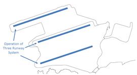
The project will consist primarily of a new third runway with associated taxiways, aprons (or aircraft stands), as well as new passenger concourse buildings and expansion of the existing Terminal 2 (T2) building.  Included in the project will be related airside and landside works and associated ancillary and supporting facilities, which are also described in this section and summarised in Appendix 4.1.

Land Formation

4.2.1.2      Based on the preferred airport development option identified in Chapter 3 and as described in previous sections, land is required to be formed to the north of the existing airport island through land formation, which will provide a platform for the development. The proposed land formation works will mainly include:

¡  Land formation of not more than 650 ha to the north of the existing airport island with partial construction over the contaminated mud pits (CMP). The area of land formation is defined to be the area at and above the high water mark of +2.3 mPD; and

¡  Modification and integration of the existing seawall at the northern, western and eastern sides of the existing North Runway into the new land formation and construction of new seawall around the land formation.

Airfield Facilities

4.2.1.3      The proposed airfield facilities will mainly include:

¡  Construction of a third runway, related taxiway systems, associated airfield infrastructure, aircraft navigational aids, approach lighting systems and new Hong Kong International Airport Approach Area (HKIAAA) beacons;

¡  Construction of the third runway passenger concourse aprons;

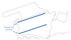
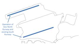
¡  Temporary closure and modification of the existing North Runway along with related taxiway systems; and

¡  Expansion of the freighter aprons in the existing Midfield area between the existing north and south runways.

Passenger Facilities

4.2.1.4      The proposed passenger facilities will mainly include:

¡  Construction of the third runway passenger concourse (TRC) and passenger fixed link bridges;

¡  Expansion of the existing passenger T2;

¡  Extension of the Automated People Mover (APM) and associated depot and maintenance / stabling areas; and

¡  Expansion of the Baggage Handling System (BHS) and associated baggage halls and early bag store.

Ancillary Facilities

4.2.1.5      New ancillary facilities will be provided to support the operational needs of the third runway passenger concourse and airfield facilities. These ancillary facilities will be located on the west and east sides of the proposed land formation area (i.e., within the western support area and the eastern support area respectively) and will accommodate utility buildings, airport support development that may include but not limited to aviation-related facility and other government facilities as required, air cargo staging, catering, aircraft maintenance, aircraft engine run-up (engine testing) facilities, ground services equipment area, early bag storage facility, fire station, fire training facility, petrol fuelling station, new air traffic control towers (ATCTs), Hong Kong Observatory (HKO) facility, mobile phone system antenna towers, stores, security gate houses, etc.

Infrastructure and Utilities

4.2.1.6      The proposed infrastructure and utilities will mainly include:

¡  Expansion of the landside and airside road network in the passenger, cargo and maintenance areas and landside transportation facilities, including new car parks;

¡  Construction of new airside road access, including the construction of new airside road tunnels and ramps, to connect the new third runway facilities with the existing airport;

¡  Modification of existing and construction of new land-based infrastructure including the seawater cooling and flushing system, stormwater drainage system, greywater system, sewerage network and potable water supply, Towngas supply, 132 kV / 11 kV and other power supply networks, communication networks; and

¡  Modifications and re-provisions to existing marine facilities including the underwater aviation fuel pipelines between HKIA and the off-airport fuel receiving facilities at Sha Chau, the associated underwater 11 kV cable and pilot cable and sea rescue boat points.

4.2.1.7      The key project components are shown in Drawings No. MCL/P132/EIA/4-001 to MCL/P132/EIA/4-007. Details of the main project components are presented below.

4.2.2        Land Formation

4.2.2.1      The main components of land formation comprise modification and integration of the existing seawall, ground improvement of the underlying marine sediments, seawall construction, filling, and surcharge. Ground improvement in lieu of dredging will be adopted to minimise any impacts to water quality and marine ecology.

Modification of Existing Seawall

4.2.2.2      To connect the new land formation area with the existing airport island, the seawall along the northern perimeter of the airport island needs to be modified to interface with the new land formation. It is considered that the armour rock of the existing seawall can be reused for construction of the new seawall, subject to design development.

Ground Improvement of the Underlying Marine Sediments

4.2.2.3      The ground improvement methods to be adopted vary depending on location (within or outside the CMP boundaries) and the ‘land type’ to be supported (see Drawing No. MCL/P132/EIA/4-001). The proposed ground improvement scheme and the applicable zones are shown in Table 4.1, and the proposed general arrangement of each ground improvement method is described in Table 4.2.  Deep cement mixing (DCM) is the only preferred ground improvement method for any locations within the CMP area. Outside the CMP area, a number of preferred ground improvement methods are proposed, and the actual combinations of ground improvement methods to be adopted for different locations will be subject to the detailed design.

Table 4.1: Preferred Ground Improvement Methods to be Adopted at Various Locations Within / Outside CMP Area

Location

Preferred Ground Improvement Method


Within CMP area

Outside CMP area

Runway

DCM

Stone Columns / Sand Compaction Piles / Vertical Sand Drains / DCM

Seawall

DCM

Steel Cells / Stone Columns / Sand Compaction Piles / Vertical Sand Drains / DCM

General land formation area

DCM

Prefabricated Vertical Drains (PVD) / Sand Compaction Piles / Stone Columns / Vertical Sand Drains / DCM

Table 4.2: General Arrangement of the Various Ground Improvement Methods

Ground Improvement Method

General Arrangement

Deep Cement Mixing (DCM)

Under seawalls – DCM will be arranged in panels and extending inward from below the seawall. The panels comprise continuous DCM clusters, each composed of mutually overlapping columns, and will penetrate into firm stiff alluvial material that comprises of firm clay underlying the soft marine sediments.

General land formation area / under runway – DCM will comprise individual clusters, with each cluster typically comprising mutually overlapping columns.

Prefabricated Vertical Drains (PVD)

General land formation area – PVD are proposed to be installed through the full thickness of the soft silt and clay underlying the seabed, with a surcharge preloading applied to the area to accelerate consolidation.

Sand Compaction Piles

Where sand compaction piles are adopted instead of stone columns (for either seawall, runway areas or general land formation areas), these will be arranged in a triangular grid pattern.

Steel Cells

Seawalls – The steel cells will form part of the seawall structure and will be installed to above sea level. Each cell will be constructed as a single unit and delivered to site using semi-submersible barges and custom-built installation barges which can install the cells without infringement of the airport height restriction, to facilitate the commencement of filling within a practical time frame.

Stone Columns

Under seawalls – Stone columns will be placed in a triangular pattern and will be toed-in to the top of firm to stiff alluvial material underlying the soft marine sediment. In conjunction with steel cells, stone columns will be placed to seaward and on the land formation side of the steel cells to support the revetment structure and the land formation fill respectively.

Under runway – The arrangement of stone columns is similar to the proposed ground improvement under seawalls. Sand compaction piles may also be adopted as an alternative.

Vertical Sand Drains

Vertical sand drains may be adopted in the transition areas between the various other ground improvement methods. The sand drains will be arranged in a triangular grid.

4.2.2.4      Prior to commencement of ground improvement activities, a 2 m thick sand blanket will be laid on the seabed to contain and prevent the release of marine sediment during ground improvement activities. Around the outer parts of the seawalls, the sand blanket may be replaced by a gravel blanket to resist potential scouring.

Seawall Construction

4.2.2.5      The majority of the seawalls for the airport expansion as shown in Figure 4.1 will comprise rock sloping seawalls, except for some localised areas (e.g. at the sea rescue landing points and marine loading points) where vertical seawalls are required. These seawalls will cover the entire boundary of the new land formation. The total length of seawall is approximately 13 km. Beyond the toe of the seawall, there will also be scour (stone) aprons to protect the seawall toe against erosion. During construction phase, ground improvement and construction of the scour aprons will extend beyond the seawall toe.  

Figure 4.1:     Typical sloping seawall section

Ground Improvement


4.2.2.6      As part of the seawalls, two permanent boat landing points are required for emergencies (see Drawing No. MCL/P132/EIA/4-001). A berthing point will be located near the midpoint of the future north shore seawall, and an onshore boat point will be located near the seawall in the western support area. These landing points include provision of landing stairs and jib boom boat cranes for rapid deployment of small emergency vessels. Vertical seawalls will be provided at these locations.

Land Filling

4.2.2.7      To form the land and seawalls, different fill materials including rock fill, public fill, sand fill, rock armour and graded filter layer will be used. Seawalls will comprise of rock fill as the seawall core, and rock armour and graded filter layer to form the protective layers. Sand fill or a mix of sand fill and public fill will be adopted as the marine filling material, while a combination of sand fill and public fill will be adopted for land filling activities. Use of public fill will be maximised as far as practicable subject to the availability of public fill material during the construction of the 3RS. Vibrocompaction will be carried out to compact the sand fill materials while vibratory rollers will be used to compact the public fill after filling.

Temporary Surcharge

4.2.2.8      To facilitate the new land formation, the application of temporary surcharge (primarily marine sand or public fill) is required. During each stage of land formation, surcharge removed from a completed works area will be reused as fill material in other active works areas, thereby minimising the amount of surplus surcharge material that needs to be disposed of offsite after completion of all land formation.

4.2.3        Airfield Facilities

4.2.3.1      This section describes the airfield elements of the project, which include the construction of the new third runway and associated taxiways and passenger concourse aprons, as well as modifications to the existing HKIA North Runway and facilities (see Drawing No. MCL/P132/EIA/4-002). 

Third Runway, Taxiways and Aprons

4.2.3.2      The third runway (or new North Runway) and its associated taxiway system have been designed to comply with International Civil Aviation Organization (ICAO) Code F requirements. The new runway would be 3,800 m long and 60 m wide with 7.5 m wide shoulders on either side. Rapid exit taxiways will serve each end of the new North Runway at an angle allowing aircraft to leave the runway at a higher taxiing speed. Two parallel taxiways would be located to the south of the new North Runway. The TRC apron will be located in-between the taxiways and are planned to accommodate approximately 110 aircraft parking stands. A main ATCT located in southern TRC apron with link bridge to the TRC, and an auxiliary tower at the western support area are proposed. The layout of this is shown in Drawing No. MCL/P132/EIA/4-002. New airfield ground lighting, approach lighting, navigational aids and other supporting infrastructure will be provided for the new third runway and its associated taxiway system.   

4.2.3.3      Construction of the third runway, taxiways, aircraft parking stands, apron roads and airside roads will involve new paving works and installation of associated infrastructure. A flexible pavement is proposed for the runway and taxiways, consisting of an asphalt wearing course and base course on a granular base. For the aircraft parking stands (aprons), a rigid pavement type is proposed, consisting of concrete surface course on lean concrete base layer. Recycled materials will be used in the pavements where possible, taking into account overall loading requirements.  The aircraft manoeuvring pavements (runways and taxiways) will have paved shoulders constructed of flexible pavement. Screens will be installed at locations where jet blast protection from outboard aircraft engines is required. Underground utilities will be installed in stages as pavement construction proceeds.

Modifications to Existing North Runway

4.2.3.4      As part of the changes to accommodate the third runway, the existing North Runway will be modified to become the new centre runway. Works required for the proposed modifications will include runway reconfiguration, construction of one wrap-around taxiway at each end of the runway, and two parallel taxiways and rapid exit taxiways to the north of the runway. The geometry of the new taxiways would be similar to those provided for the new North Runway in order to comply with ICAO requirements.

4.2.3.5      The proposed pavement construction for the new taxiways of the new centre runway would be the same as that for the new taxiways serving the new North Runway. As the existing North Runway (or the new centre runway) will become the main departures runway in the new 3RS, re-profiling and strengthening of the existing pavement is proposed. The existing airfield ground lighting, navigational aids, approach lighting and airfield infrastructure would be modified and extended to serve the modified runway and new taxiway system.

Expansion of Midfield Apron

4.2.3.6      As part of the committed Midfield development described in Section 2.2.4, additional aircraft stands will be developed to serve both passenger and cargo aircraft uses to meet the near-term demand prior to the opening of the TRC and the associated aprons.  With the additional parking stands developed within the future TRC aprons, the passenger aircrafts using the Midfield can then be reallocated to the TRC aprons. The available capacity from the western half of the Midfield apron will then be designated as the cargo apron to meet the forecasted parking stand demand for the freighter aircrafts. The construction activities associated with reallocation of use would involve only minor structural and finishing works.

Construction of Runway Approach Lights

4.2.3.7      Approach lights will be required to be installed within the paved runway areas of the new third runway and the existing North Runway. For the third runway, the approach lights will extend off the eastern and western edges of the new land form into the adjacent marine waters. The section of the approach lights to be erected in the sea will be installed on a small marine structure supported with pile, on top of which the light barrette will be placed. A maintenance deck in the form of a metal bridge extended from the two ends of the runway will be installed to allow access to these structures. For the existing North Runway, during the closure period, existing approach lights will be demolished for facilitating the land formation works.  After the completion of land formation work, approach lights for existing North Runway will be installed on reclaimed land.

4.2.3.8      The eastern section of the approach lights for the third runway is anticipated to extend into an area of CMP. Therefore, it is currently proposed that the area beneath each light stand will be improved with DCM prior to piling. This approach will facilitate the management of the material extracted from piling.

Construction of HKIAAA Marker Beacons

4.2.3.9      As part of the future requirements for operation of the new third runway, a new Hong Kong International Airport Approach Area would be designated at the marine waters surrounding the new runway strip. This future HKIAAA would be a restricted access area and markers positioned along the boundaries of this future HKIAAA would be required to ward vessels away from the perimeter of the HKIAAA. Based on discussions with Marine Department, it is expected that fixed beacons (instead of anchored buoys) would be required.

4.2.3.10    To demarcate the HKIAAA boundary, it is proposed to install beacons along the boundary of the HKIAAA. The indicative locations of these beacons are shown in Drawing No. MCL/P132/EIA/4-002. Depending on the requirements by Marine Department, these nine beacons may need to be provided as fixed structures. Based on initial scheme design, the beacons are anticipated to be single piled structures topped with steel light posts.

Expansion of Aviation Fuel Hydrant System

4.2.3.11    The new aviation fuel supply network will be similar to and extended from the existing HKIA network. The new system will consist of a dual piping network that will run underneath the existing North Runway in a dedicated fuel cell located adjacent to the western airside road tunnel. The extended network will feed the hydrant fuel pits located at each of the TRC aircraft parking stands (see Drawing No. MCL/P132/EIA/4-004) in addition to those stands in the expanded Midfield area. Supporting systems similar to the existing one including the pipeline leak detection, the impressed current cathodic protection and the emergency stop button system will also be provided to support the operation of the fuel hydrant supply network.

4.2.3.12    To meet the additional fuel distribution capacity, extra fuel hydrant pumps would be installed at the existing on-airport aviation fuel tank farm (AFTF). The installation of new pumps will require the modification of connecting valves and pipework, an additional 1,500 kVA transformer for supplying power to the new electric motors, additional programmable logic controller racks to suit the SCADA (supervisory control and data acquisition) requirement and extension of the fire service system. All existing fuel tanks and other major equipment and facilities at the AFTF will be unaffected.

4.2.4        Passenger Facilities

4.2.4.1      This section describes the main passenger-related elements of the project, which include the new third runway concourse and T2 building as well as the APM and BHS facilities (see Drawing No. MCL/P132/EIA/4-003). 

Third Runway Passenger Concourse

4.2.4.2      A new world class passenger terminal building will be constructed as part of the proposed airport expansion.  The TRC building design will be composed of a ‘Y-Y’ shape in plan and will serve approximately 60 contact stands with associated fixed link bridges and gates along its entire perimeter. The building form features a high, undulating roof over its entire footprint with walls comprising steel and glass. When completed, the TRC will comprise several levels, covering a gross floor area of about 530,000 m². There will be baggage tunnels, APM tunnels and stations, mechanical plant rooms, courtyard, retail area and government offices, etc.

4.2.4.3      The TRC building will be designed to be energy efficient and to incorporate sustainable design features. Solar heat gain will be minimised using shading and insulation, high performance glazing and a light-coloured roof surfaces. Energy efficiency solutions will include optimised mechanical and electrical systems, solar power, as well as efficient lighting and day lighting strategies.

4.2.4.4      Details of the construction method are subject to further engineering review and are not yet confirmed. Nevertheless, typical construction of the new passenger concourse begins with piling foundations to support the building. Pre-bored H-socket steel concrete pile and/or large diameter bored piled foundations may be used. Some of the piles will pass through the CMP material that will have been subjected to DCM improvement. The walls and building structure will be formed by in-situ concrete slab, columns and beams with precast T-beams / plankings. Steel structure design may also be considered. At the current stage of design development, it is anticipated that the roof will comprise a steel truss structure with prefabricated panel that will be erected once the supporting concrete structures are in place.

Terminal 2 Expansion

4.2.4.5      T2 is currently serving as a departures terminal, coach station and retail hub and is linked to T1. With the planned expansion of HKIA into a 3RS and to meet the anticipated increase in passenger and cargo demands, T2 will be expanded into a full service processing terminal (for arrivals, departures and transfers) serving the TRC.

4.2.4.6      The expanded T2 will comprise an expanded main terminal building, new annex buildings adjacent to existing T2 (for coach staging, car parking, loading / unloading and limousine lounge, etc.), an underground APM interchange station (AIS) and BHS basement. The key facilities to be provided as part of the expanded T2 include airline check-in, departures, arrivals and baggage halls; APM facilities; ground transportation facilities; retail facilities; aviation related facilities; and other systems and works required for the operation of T2.

4.2.4.7      In addition to the key facilities within the T2 premises, landside supporting facilities and utilities works will be required to be built, expanded and enhanced to support the future passenger and cargo demands and ensure smooth and reliable airport operations. These include various land transport (e.g. private car, coach, bus, taxi and rail) facilities and landside transportation infrastructure required to maintain the mass transportation network (along with the Airport Express Line railway) serving HKIA as well as utilities and associated diversion works.

4.2.4.8      The existing T2 will be modified extensively into the future expanded T2.  The works include the demolition of part of the existing terminal building and the construction of the expansion works within and adjacent to the existing T2. As land is available for the expanded T2, the general construction method for T2 expansion is envisaged to be the traditional bottomup construction method. After completion of excavation for AIS and BHS basement and piling works for AIS, BHS basement and expanded T2, the reinforced concrete construction for building structures will be started from the lowest to the highest levels. The steel roof of T2 expansion will be erected after completion of concrete structure at the various levels.

Automated People Mover System

4.2.4.9      As part of the third runway project, a new APM TRC line will be constructed to transfer passengers between the TRC and the expanded T2 and new AIS. The existing T1 Line will also be extended to the new AIS, while the existing APM SkyPier Line will also be modified and connected to the new AIS station.

4.2.4.10    The existing underground APM depot beneath the T2 building will be relocated and expanded to a combined depot for the TRC Line and the T1 / SkyPier Lines. The new depot will be located east of T2 underneath the existing golf course and will accommodate both the existing T1 / SkyPier and planned TRC systems in adjacent maintenance areas. At this stage of design, the consolidated depot is anticipated to be approximately 300 m by 120 m and will be located north of the existing SkyPier Line guideway (depth of approximately -6.5 mPD).  However, certain construction-related issues including the presence of existing rock outcrops at that location may require the depot to be located further north beneath existing SkyCity parking lot.

4.2.4.11    An APM tunnel approximately 3 km long will connect the east TRC with the AIS in T2. The current design indicates that the tunnel will run from T2 basement level, beneath the eastern support area to the new east TRC station, with ventilation buildings located between the T2 and TRC. The tunnel will be extended nearly another kilometre to the west TRC station, with a maintenance and stabling siding located approximately 300 m beyond. 

4.2.4.12    At this stage of project development, excavation for the underground APM depot and tunnel is anticipated to be carried out by using top-down methods and cut-and-cover respectively, subject to future detailed design.

Baggage Handling System

4.2.4.13    A new Baggage Handling System will be designed to handle the routing and delivery of baggage between the TRC, T1 & T2 and ITT.  The proposed BHS tunnel will be approximately 3 km in length and will follow similar route between the TRC and T2 as for the APM tunnel. The bag hall will be built at apron level and early bag store will be built at the eastern support area. At this stage of project development, excavation for the BHS tunnel is anticipated to be carried out by cut-and-cover method, subject to future detailed design.            

4.2.5        Ancillary Facilities

4.2.5.1      Majority of the proposed ancillary facilities that would be required for the TRC are planned to be located in the eastern and western support areas (shown in Drawing No. MCL/P132/EIA/4-002). These proposed ancillary facilities would include air traffic control towers, airside and landside fire stations,  a fire training pit (to be relocated from the southern part of the airport island), petrol filling station, aircraft maintenance hangars, an aircraft engine run-up facility (ERUF) for performing aircraft engine test runs for the purpose of trouble-shooting or maintenance, air cargo staging facilities, flight catering facilities, ground service equipment maintenance facilities and storage area, airside communications and office buildings, cross dock facility, seawater pumping stations, meteorological station and other airport support facilities or aviation-related developments

4.2.6        Infrastructure and Utilities

4.2.6.1      The installation of new infrastructure and utilities, as well as the relocation or extension of existing utilities, will be required to support the new third runway project.  The major utilities that would be affected include the seawater cooling system, drainage network, potable water supply, sewerage network, gas, power, telecommunications, airport systems, and other aviation related utilities and systems.

Road Network

4.2.6.2      Sections of both the existing airside and landside road networks will require to be upgraded to serve the increased traffic generated by the expansion of HKIA. Modifications to the network will take the form of new sections extending the existing network, provision of grade separated sections of carriageway, and the construction of new airside road tunnels to provide connectivity across the airport (see Drawing No. MCL/P132/EIA/4-004 to MCL/P132/EIA/4-007).

4.2.6.3      To ensure the smooth opening and operation of the expanded T2, the departure road and the associated road network will be completed before the operation of expanded T2. The preferred road network option, i.e., Option F, comprises mainly elevated roads (a total of approximately 4 km in length subject to detailed design) with some realignment of atgrade roadways as shown on Drawing No. MCL/P132/EIA/4-005. Local roads and junction improvement are also required.

4.2.6.4      The existing perimeter roads are required to be extended to provide access to the eastern and western support areas. Connection to the western support area will require an elevated section of viaduct approximately 500 m in length over the existing western emergency sea berth to allow uninterrupted emergency access.

4.2.6.5      Within the existing southern cargo area, widening of existing roads and the construction of approximately 1.5 km of viaducts over existing at-grade interchanges are required to cater for the increase in traffic flows. The road sections to be constructed / modified are shown in Drawings No. MCL/P132/EIA/4-006 and MCL/P132/EIA/4-007.

4.2.6.6      For construction of the viaducts, it is anticipated that bored piles / pre-bored H piles foundation will be adopted as the main piling system for the viaduct roadways. Pile caps, bridge piers and pier heads will then be progressively constructed following the completion of piling works.

4.2.6.7      Due to the need of compliance with the airport height restrictions, which limits the selection of construction machineries, traditional cast in-situ formwork or balanced cantilever with form travellers is currently assumed for the construction of the bridge decks. Once the bridge structures are constructed, the parapets, encased utilities (if any), waterproofing, pavement, footpath (if any), lighting and street furniture will be installed subsequently.

Airside Road Tunnels

4.2.6.8      Two airside road tunnels will connect the existing cargo area to the TRC area to facilitate airside movements across the airport (shown in Drawing No. MCL/P132/EIA/4-004). The western road tunnel will be approximately 1.5 km long and the eastern road tunnel will be approximately 1.2 km long. These tunnels will connect to an approximately 3 km road tunnel that runs along the southern edge of the TRC.  Two ramps approximately 0.5 km long each, will provide surface access to the TRC apron. 

4.2.6.9      At this stage of project development, it is anticipated that construction of these tunnels underneath the existing North Runway will be carried out in sections by cut-and-cover or other appropriate methods during the period of programmed runway closure.

Expansion of Seawater Cooling System

4.2.6.10    At this stage of project development, it is proposed that a new seawater pump house will be constructed on the edge of the eastern support area to deliver cooling water to the chiller plant rooms in the TRC and to provide flushing water for the airport expansion. Seawater from the new pump house would be pumped to the TRC. The pump house will be a single storey concrete building with two basement levels to house the seawater pumps and associated equipment. It is anticipated that the basement will be constructed by using open cut excavation technique with a shallow foundation.

4.2.6.11    The existing seawater pump house (SWPH-1) provides cooling water for T1 and T2. To accommodate the proposed land formation and increased future demand, it is proposed that this facility is re-provisioned at a new location with an increased capacity to provide for the cooling demands of T1, T2 and AIS.

Stormwater Drainage System

4.2.6.12    Surface water runoff would be collected through a network of drains and pipes to stormwater outfalls. It is anticipated that six new stormwater outfalls will be provided: three along the northern edge of the new third runway; one at the eastern end of the new runway; and two that will comprise extensions to existing stormwater outfalls currently located along the northern edge of the existing airport island (see Drawing No. MCL/P132/EIA/4-004). The four existing stormwater outfalls will be consolidated into two new stormwater outfalls, which will be re-located to the east and northwest of the extended landform of the new centre runway. A tributary drainage and first flush oil separation system will be provided for aircraft parking and maintenance aprons. 

4.2.6.13    Construction for the new drainage culverts is envisaged to commence after completion of the land formation activities, except for the outfalls, which will be constructed as part of the overall seawall construction. Construction is anticipated to be open cut trenching and placement of precast or cast in-situ concrete box culvert units. It is envisaged that the outfalls will be placed as precast units at an appropriate time during the seawall construction, and temporary bulkheads will be installed to allow the land formation works and the culvert extensions to be completed (to keep the tides from back flooding through the outfall structures). The temporary bulkheads will be removed after the culvert extensions are completed and the drainage system is brought into service.

4.2.6.14    For the existing outfalls to be re-provisioned, construction is anticipated to be open cut trenching and placement of precast concrete or cast in-situ box culvert units. For the connecting sections with the existing outfalls, traditional in-situ concrete construction would be required. It is anticipated that works for these connection areas would be undertaken during the dry season in order that individual drainage culvert cells may be isolated for interconnection works.

4.2.6.15    During land formation, temporary drainage channels across the new land formation area will be provided. Upon completion of the outfall extensions, the temporary channels will be backfilled.

4.2.6.16    Subject to further detailed design, temporary and permanent diversion of existing box culvert would be required.

Sewerage System

4.2.6.17    Sewage generated from the new development will be collected by a local sewerage network comprising gravity pipes and conveyed to new pumping stations that would be located within the eastern and western support areas. Due to the increasing generation of sewage from the new developments under TRC and T2 expansion, it is anticipated that the capacity of the existing sewage pumping stations (PS1, PS2 and PS12f) is not able to handle the increased flow volume collected from the network after Year 2023.  The pumping stations are required to be upgraded to increase its capacity to cope with the future flow.  In addition, as the proposed APM tunnel is located directly underneath the existing pumping station PS12f, it is preliminarily proposed at this stage to relocate the upgraded PS12f to the vacant land on the southeast side of the existing airport north interchange.

Greywater Treatment and Recycling Facility

4.2.6.18    A new greywater treatment and recycling facility is proposed as part of the airport expansion to reduce potable water consumption.  Wastewater collected from kitchens, washroom sinks, and aircraft catering and cleaning activities from the new facilities associated with the airport expansion will be treated onsite for reuse in landscape irrigation or cleansing related activities.

4.2.6.19    Based on the estimated demand for treated greywater for the airport expansion, a greywater treatment facility of the order of 700 m³/day production capacity is initially proposed, subject to the detailed design. The greywater treatment facility would be located inside a plant building in the eastern support area. The plant would be designed to produce treated water quality that achieves compliance with Architectural Services Department’s Design Guidelines for Rainwater and Grey Water Recycling Installation (BSB Circular No 13 of 2008).       

Other Utilities and Services

4.2.6.20    Other utilities and services including potable water supply, gas, communications, airport systems and power supply will also be provisioned for the airport expansion areas. Design and construction of these utilities will tie in with the overall design and construction of the individual facilities to be provisioned within the airport expansion area.

Diversion of Submarine Aviation Fuel Pipeline

4.2.6.21    As discussed in Section 3.7.3, diversion of the existing submarine aviation fuel pipeline is required in order to maintain continuous fuel supply to HKIA. Diversion of the existing submarine aviation fuel pipelines will use a horizontal directional drilling (HDD) method forming two rock drill holes by drilling through bedrock from a launching site located at the west of the airport island to the daylighting point adjacent to the offshore receiving platform at Sha Chau. Two new 500 mm diameter pipelines will be installed through the drilled tunnels. The total length is approximately 5 km.

4.2.6.22    The HDD method involves installation using a surfaced-launched drilling rig and a steerable down hole system. Prior to commencement of the HDD, marine site investigation (SI) works are required along the proposed HDD alignment within the Sha Chau and Lung Kwu Chau Marine Park to provide detailed geological information for detailed design. This would involve drilling SI boreholes at several locations within the marine park, and setting up temporary drilling vessels / platforms. Upon confirmation of the alignment, the HDD drilling will be controlled by a target tracking steering device that is located at the drilling head.

4.2.6.23    Upon completion of the drilling and reaming of the HDD holes, the permanent aviation fuel pipes will be pushed from the HDD launching site on the airport island to Sha Chau. To limit the impact to Sha Chau Island, pipe fabrication will be done at the airport island side, however a temporary floating working platform is required between Sha Chau Island and the offshore receiving platform (where the water is in the order of 4 m deep) to facilitate the works. The remainder of the pipe laying between the HDD launching site on the airport island and the existing seawall will be installed by open trench method. A new isolation valve chamber will be constructed to allow section isolation for ‘tie-in’ of the new pipelines with the existing system.

Diversion of Submarine 11kV Cables

4.2.6.24    As discussed in Section 3.7.4, diversion of the existing power cables is required in order to maintain continuous power supply to the facilities at Sha Chau. Diversion of the submarine cables will use a direct bury (water jetting) method.  Water jetting is currently the proposed preferred method as it avoids the need for trench excavation and associated disposal of excavated materials.  Works will be conducted beneath the seabed from the edge of the airport island to the ‘connecting location’ at least 500 m outside the boundary of Sha Chau and Lung Kwu Chau Marine Park.  A field joint will be installed to connect the diverted cable to the existing cables running to the Sha Chau Island. While excavation is avoided by adopting the water jetting method, a limited amount of excavation will be needed at the field joint area. The length of cable installation is approximately 6 km marine and approximately 0.3 km landside, with a burial depth of 3 m to 5 m below seabed level.

4.2.6.25    At the field joint, the existing cables will be exposed for a length of approximately 120 m using open trench method. The trench will be approximately 5 m deep and 32 m wide. On completion of the field joint, the cables will be re-laid to a depth of 3 m to 5 m below seabed level and the open trench will be reinstated. During the field joint works, power via the cables will need to be temporarily suspended and a temporary power supply to Sha Chau (via diesel generators) will be provided on Sha Chau Island.

4.2.6.26    At the daylighting point of the submarine cables, the cables will cross the existing seawall. A works area on the west side of the existing airport island will be required for the cable daylighting and jointing to the existing landside cables. The existing seawall at HKIA will be removed by open cut method and cable ducts will be installed before reinstating the seawall. The cables will then run underground, crossing the existing roadway (via cross road ducts) and along the east shoulder area of the roadway to the designated joining location.

4.3          Project Programme and Construction Sequence

4.3.1        General Phasing

4.3.1.1      The tentative programme for operation of the 3RS will be in Year 2023. Given the scale and complexity of the project, construction and the concurrent runway operational configuration will be implemented according to the general phases as shown in Table 4.3 below. Some infrastructure such as the TRC may be implemented in phases taking into consideration the expected demand. Hence the three-runway airfield system will be in operation before the full completion of all infrastructure associated with the project.


Table 4.3: Summary of Construction and Runway Operational Configuration Phasing

Phase

Description

Runway Operational Configuration

Timeframe

Advanced Works

Diversion of the submarine pipeline and power cable

2015 to 2016

Phase 1

Land formation works will commence before subsequent construction of third runway, new taxiways and the new TRC. Expansion of T2 will also be commenced. The existing two-runway system remains operational throughout construction phase.

2016 to 2021

Phase 2

Upon completion of the third runway and associated taxiways, the existing North Runway will be closed for modification works, while construction activities for the TRC and aprons, vehicle tunnels and reconfiguration of T2 are ongoing. During this interim period, the existing South Runway and the new third runway will be operational.

2021 to 2023

Phase 3

Upon completion of all essential infrastructure and facilities including part of the TRC and aprons and expanded T2, the airport will operate under the 3RS. Construction of the remaining facilities will continue until completion.

2023 and after


4.3.1.2      The tentative construction programme is provided in Appendix 4.2. This programme is subject to further changes during the course of the scheme designs. Construction will proceed in the general order of diversion of the existing submarine power cable and aviation fuel pipeline, land formation, infrastructure and superstructures. The general construction sequences (grouped into major works components/areas) are described below.

4.3.2        Construction Sequence for Advanced Works

4.3.2.1      For the submarine aviation fuel pipelines, marine SI will first be conducted along the proposed HDD alignment to provide the necessary geotechnical information for construction of the submarine pipelines. Within the Sha Chau and Lung Kwu Chau Marine Park, a total of four SI boreholes (each approx. 200 mm in diameter) will be drilled to the bedrock level by drilling vessel / jack-up platform within the Marine Park. Subsequent drilling operations for both pipelines will be carried out simultaneously. Drilling works will proceed from the HDD launching site at the airport island and is expected to be completed in about a year. Upon completion the drilling and reaming of the HDD holes, the permanent aviation fuel pipes will be pulled from Sha Chau to the HDD launching site. The installation of the pipelines including testing and commissioning is anticipated to take another year.

4.3.2.2      For the submarine 11 kV power cable, construction is anticipated to commence at the landside connection point and progress towards the field joint at the navigable waters north of the existing airport island for completion. The construction work will take about a year to complete.

4.3.3        Construction Sequence for Land Formation

4.3.3.1      Due to the large size of the project, the land formation area will be divided into a number of smaller areas surrounded by a larger temporary works area. The boundary of the temporary works area (shown in Drawing No. MCL/P132/EIA/4-008), where construction vessels will be present or moving around the proposed land formation footprint, will be demarcated by floating booms. The general construction sequence / methods for land formation activities are as follows:

1.          Land formation from seabed to above water level:

a.            Place sand blanket on the seabed

b.            Conduct ground improvement works

c.            Complete a minimum of 200 m leading seawall up to and above seawater level

d.            Deposit marine fill

2.          Land formation above water level:

a.            Place the fill materials up to an intermediate level and apply compaction to the fill, and repeat up to formation level

b.            Place additional fill on top to act as surcharge to the level as required

c.            Hold the surcharge for a period of time and subsequently remove to the formation level

4.3.3.2      For works areas along the existing northern edge of the airport island, modification of the existing seawall will be required, and it is envisaged that this will be carried out in sections according to the progress of the land formation works to ensure that maximum protection of the existing structures along the northern edge of the airport island is maintained during the construction process (while the North Runway is still in operation).

4.3.3.3      Construction of the new approach lights for the third runway will commence as soon as the adjacent seawall is complete, but they will need to be completed and tested prior to opening of the third runway. Re-provisioning works for the existing North Runway approach lights are constrained by the requirement to maintain normal runway operations during the land formation works. In addition, the land formation plant and vessels are required to maintain a safe distance away from the approach lights so as not to interfere with their operation. Consequently, the re-provisioning activities cannot occur until much later in the construction programme, after completion of the land formation activities in the adjacent works areas.

4.3.4        Construction Sequence for the Third Runway Facilities

4.3.4.1      The construction of the third runway will commence immediately after the surcharge for that section of works area is removed. The general construction sequence is:

1.         Install all underground utilities including stormwater box culvert and associated drainage system, seawater and potable water pipes, cable and communication ductworks

2.         Excavate and prepare the compacted subgrade. Place and compact the crushed aggregate based and sub-base course in layers

3.         Install airfield ground lights (AGL) ductwork and light cans

4.         Construction of airside perimeter roads, security fencing and gate houses

5.         Install approach light / HKIAAA beacons structures and systems

6.         Place the asphalt base course, wearing course for runway and associated taxiway system

7.         Install the AGL and airfield line marking

8.         Testing and commissioning and follow with flight check.

4.3.4.2      Construction of the various building and infrastructure facilities for the third runway will commence immediately upon completion of each parcel of landform. The sequence of construction will broadly comprise the following:

1.         Site formation works i.e. site grading, installing cofferdam / well points for water cutoff and general excavation will be firstly carried out for the construction of infrastructures and superstructures;

2.         Install piles for TRC and other structures i.e. fixed linked bridge.  After piles installation, construction of APM stations under eastern and western TRC will then be commenced.  A combination of in-situ column-beam structural frame and precast concrete T-beams and slabs will be adopted for the construction of TRC superstructure.  Steel roof truss with prefabricated roof panel and façade will then be erected and fixed after the completion of concrete structures;

3.         Piles for  APM tunnels and BHS tunnels (if any) will also be installed concurrently. After the completion of piles installation, blinding and waterproofing membrane will be laid and construction of APM & BHS tunnel box structures will be commenced section by section.  Completed tunnel box section will then be wrapped by waterproofing  membrane and backfilling work will be carried out to final site formation level;

4.         Install underground utility and infrastructure including drainage, sewerage, fuel hydrant system etc. at airfield;

5.         Place the asphalt base course, wearing course and pavement quality concrete as paving for stands and taxiways;

6.         Construct airside, landside road connections, security fencing and associated gate houses; 

7.         Install services, fit-outs and systems for the TRC, APM and BHS tunnels and other buildings;

8.         Carry out testing and commissioning; and

9.          Landscaping.

4.3.4.3      For infrastructure located under the existing North Runway (i.e. vehicular tunnel and fuel pipes, etc.), construction will commence after closure of the runway (when the new third runway is under operation).

4.3.5        Construction Sequence for Infrastructure and Facilities on the Existing HKIA

4.3.5.1      Upon closure of the existing North Runway, modification works will commence in the runway / taxiway areas including paving works for the runway, main taxiways and new wrap-around taxiways, and installation of AGL and line markings.

4.3.5.2      Construction of the T2 expansion will occur in several stages, which include (1) advance works, (2) piling and substructure, (3) existing T2 modification and expansion, and (4) connecting infrastructure.

1.         The advance works comprise car park reprovision and temporary road diversion followed by diversion of utilities outside the existing T2 to free up underground spaces for the construction of T2 expansion.

2.         The piling and substructure works for the T2 expansion will then commence.  Facilities to be located within the southern and eastern part of the T2 expansion such as the underground AIS, BHS basement and annex buildings will also be constructed first.

3.         The existing T2 will be fully shut down for the demolition of the part of the existing T2 structures that will not be retained and implementation of the subsequent extensive building modification and expansion works. While the existing foundation will be retained and reused, additional pile foundation will be constructed within the existing T2 footprint after completion of demolition works. Basement walls will be formed using diaphragm walls and bored cast foundation piles. A combination of in-situ concrete construction and construction from using precast concrete beams and slabs will be adopted for the main levels, while the roof will be constructed by erection of trusses followed by prefabrication of roof panels using pre-assembled jigs.

4.         Construction of the APM depot, APM tunnel, BHS tunnel, landside utilities, elevated road and at-grade road network will also be carried out concurrently to enable timely completion of the T2 expansion works.

4.3.5.3      The construction process for the realignment of existing and the construction of new sections of at-grade roadways will typically be as follows:

1.          Earthworks, excavation or embankment works;

2.         Compaction of the road sub-grade;

3.         Utilities / pipeline ducting and protection works will be installed after earthworks are completed. Road sub-base, road kerbs, road base, wearing course;

4.         Footpath, highway finishes, street furniture, lighting etc..

4.3.5.4      During construction phase, two on-site concrete batching plants with a silo capacity of >10,000 tonnes will be provisioned at the new land formation area to support the construction activities. In addition, one floating concrete batching plant will be deployed to support construction of the box culverts. The location of the plants will change as construction progresses in different works areas. Cement will be supplied primarily by barge. Two asphalt batching plants will also be required during construction phase to support the asphalt paving activities for the new runway / taxiway areas and modifications at the existing North Runway / taxiway areas.

4.3.5.5      There will also be temporary storage of sand of potentially >1 ha in size located in the TRC area as excavation works associated with the TRC progresses. While some of this sand will be reused within the site, the remaining surplus sand from the construction activities will eventually be transported off-site to the public fill banks for beneficial reuse by other projects.

4.4          Summary of Designated Projects

4.4.1.1      The project components that constitute a Designated Project under the EIA Ordinance are summarised as follows:

¡  Land formation activities for a new landform of up to 650 ha which will be less than 100 m from the nearest seawater intake (Items C.1 and C.2, Part I, Schedule 2).

¡  Provision of new facilities including airport-related facilities (Item B.1, Part I, Schedule 2).

¡  Provision of the reuse of treated sewage effluent (Item F.4, Part I, Schedule 2).

¡  Provision of rail-based facilities including an underground tunnel for the APM, associated stations and a depot (Items A.2, A.4, and A.7, Part I, Schedule 2).

¡  Provision of new roads, including roads designed as primary distributor roads (the T2 road network), comprising viaducts, and road tunnels (Items A.1, A.7 and A.8, Part I, Schedule 2).

¡  Construction activities associated with the submarine aviation fuel pipelines (including SI boreholes) that are located within the Sha Chau and Lung Kwu Chau Marine Park, and temporary power supply for the submarine 11 kV cable located within the Lung Kwu Chau, Tree Island and Sha Chau Site of Special Scientific Interest, (Items H.2 and Q.1, Part I, Schedule 2).

¡  Provision of temporary construction-related facilities including two on-site concrete batching plants and on-site storage of sand (Items K.5 and K.11, Part I, Schedule 2).

4.4.1.2      These Designated Projects have been described relevant sub-sections in Section 4.2 and 4.3.

4.5          Concurrent Projects

4.5.1        List of Potential Concurrent Projects

4.5.1.1      A review of available information has identified a number of other projects that are undergoing planning, design, construction and/or operation within the construction and/or operation period for this project. A summary of these projects are provided below. This list excludes concurrent projects that form part of the existing baseline conditions (e.g. air emissions from existing power stations, noise emissions from existing roads, and discharge from existing sewage treatment works) which are already accounted for as part of the pollutant emissions / loading inventory described in the relevant technical sections of this EIA report.

Black Point Gas Supply

4.5.1.2      This project involves construction of new submarine gas pipelines from the existing Black Point Power Station to the natural gas export facilities in southern Guangdong Province.

4.5.1.3      The approved EIA for this project (EIA-178/2009) states that the project comprises marine dredging and jetting, land reclamation of approximately 0.5 ha, installation of the submarine gas pipeline and construction of two gas receiving stations at Black Point. It is split into two phases. Phase 1 involves construction of Pipeline 1 and the co-located gas receiving station and Phase 2 involves new reclamation, construction of an artificial seawall, Pipeline 2 and a new gas receiving station.

4.5.1.4      According to communications with the project proponent in January 2013, construction activities for Phase 1 are completed, and no decision has been made on the construction programme for Phase 2. As the project is located more than 9 km away from the nearest boundary of the third runway footprint, cumulative impacts are unlikely and will not be assessed.

Container Terminal 10 Development at Southwest Tsing Yi

4.5.1.5      This project is for development of a container terminal and associated facilities at the southwestern part of Tsing Yi Island to provide at least 8 nos. of 400 m long berths. The scope of the project includes dredging, construction of seawalls, reclamation of approximately 180 ha, construction of quay decks, roads and associated infrastructure, supporting facilities, and re-provisioning of affected facilities including oil depots. A project profile (ESB-194/2008) was submitted by the project proponent for this project in 2008 and an EIA is yet to be completed.

4.5.1.6      According to communications with the project proponent in August 2013, the preliminary feasibility study for this project is ongoing and information is not yet available. Given that insufficient information is available at this stage, this project cannot be assessed for cumulative construction phase impacts. However, the new landform due to reclamation associated with this project will be taken into account in the operation phase water quality section of this EIA report.

Cycle Track between Tsuen Wan and Tuen Mun

4.5.1.7      The Project aims to provide a cycle track between Tsuen Wan and Tuen Mun together with associated supporting and recreational facilities. A project profile (ESB-224/2011) was submitted by the project proponent for the Tsuen Wan to Ting Kau section in 2011 and an EIA is yet to be completed.

4.5.1.8      According to latest information published by the project proponent on this project, the project is currently undergoing detailed design, which is estimated to be completed in phases from mid-2014 to 2015, and the programme of construction works could only be finalised upon completion of the detailed design work. Given that the construction programme is unconfirmed, this project cannot be assessed for cumulative construction phase impacts.

Development of the Integrated Waste Management Facilities Phase 1

4.5.1.9      This project is to construct and operate a modern facility for managing municipal solid waste through an advanced thermal incineration process. According to the approved EIA report (EIA-201/2011), this project comprises an incineration plant, a mechanical treatment plant, and ancillary facilities, to be constructed at the Tsang Tsui Ash Lagoon in Nim Wan, Tuen Mun and / or an artificial island near Shek Kwu Chau.

4.5.1.10    According to communications with the project proponent in January 2013, the original programme cannot be met and a revised programme is yet to be confirmed.

4.5.1.11    Nevertheless, the technical information presented in the approved EIA report has been confirmed as up to date and may be used by relevant technical assessments as part of the consideration of reasonable worst case scenarios for operation phase impact. As this project will contribute to air pollutant emissions and involves reclamation, cumulative impacts to operation phase air quality and water quality will be taken into consideration in this EIA report.

Effluent Polishing Scheme at Yuen Long Sewage Treatment Works

4.5.1.12    This project is for upgrading the treatment facilities at the existing Yuen Long Sewage Treatment Works to further improve the treated effluent quality and reduce pollution loading to Inner Deep Bay. The site is located alongside Shan Pui River in Yuen Long. A project profile (ESB-241/2012) was submitted in 2012, and the proposed works include upgrading the treatment level and modifying the existing treatment facilities and provision of disinfection facilities.

4.5.1.13    According to communications with the project proponent in August 2013, the study for this project is ongoing and information is not yet available. This project lies within the study area for water quality assessment, however, it is located at least 19 km away from the nearest boundary of the third runway footprint, therefore, cumulative construction phase impacts are unlikely, and will not be assessed. However, potential cumulative impacts to operation phase water quality will be taken into consideration in the water quality section of this EIA report.

Enhancing Land Supply Strategy Study: Reclamation outside Victoria Harbour and Rock Cavern Development

4.5.1.14    This project is to assess the feasibility of enhancing land supply through various land supply options, including reclamation outside Victoria Harbour and rock cavern development. As of March 2013, this project is undergoing a public consultation of shortlisted sites for reclamation / rock cavern development. Shortlisted sites for reclamation include Lung Kwu Tan, Siu Ho Wan, Sunny Bay, Tsing Yi Southwest and Ma Liu Shui, as well as proposed artificial islands in Central Waters. Shortlisted sites for rock cavern development include Diamond Hill Fresh Water and Salt Water Service Reservoirs, Sai Kung Sewage Treatment Works, and Sham Tseng Sewage Treatment Works.

4.5.1.15    Based on communications with the project proponent in April 2013, details of the latest construction programme and design is unknown and is unlikely to be available during preparation of this EIA for the third runway project.

4.5.1.16    Given that insufficient information is available at this stage, this project cannot be considered as a concurrent project and cumulative impacts will not be assessed.

Harbour Area Treatment Scheme - Stage 2A

4.5.1.17    The Harbour Area Treatment Scheme (HATS) Stage 2A is part of the larger HATS or Strategic Sewage Disposal Scheme committed in the late eighties to provide treatment for the sewage collected from urban areas in Kowloon and Hong Kong Island. The completed HATS Stage 1 comprised the Stonecutters Island Sewage Treatment Works (SISTW) and approximately 24 km of tunnels diverting sewage from urban Kowloon, Kwai Tsing, Tseung Kwan O and north-eastern Hong Kong Island to the SISTW. HATS 2A involves construction of an approximately 21 km long sewage tunnel to SISTW and an upgrade of the treatment capacity at SISTW as well as upgrades to eight existing preliminary treatment works along the northern and western shore of Hong Kong Island.

4.5.1.18    According to the HATS project website, construction of HATS 2A commenced in 2009 and is scheduled for completion in 2014. A further HATS Stage 2B comprising a new biological treatment plant adjacent to SISTW is under review and no implementation programme is available at this stage.

4.5.1.19    As this project will be completed before construction of the third runway, it is not a concurrent project and cumulative construction phase impacts will not be assessed. However, during operation phase, changes to the sewage discharges resulting from the project will be taken into consideration in the water quality section of this EIA report.

Hong Kong - Zhuhai - Macao Bridge: Hong Kong Boundary Crossing Facilities

4.5.1.20    The Hong Kong Boundary Crossing Facilities (HKBCF) are part of the larger sea crossing to link HKSAR with Zhuhai, Guangdong Province and the Macao Special Administrative Region, and forms the transportation hub for Hong Kong – Zhuhai – Macao Bridge (HZMB) passengers and goods clearance within HKSAR. This project is located to the east of the airport island, and serves as a transfer point for road traffic between HKLR and Tuen Mun – Chek Lap Kok Link.

4.5.1.21    This HKBCF is located on an artificial island of about 130 ha to be reclaimed off the northeast of HKIA, and will comprise cargo and passenger clearing and vehicle inspection facilities, Government offices, road networks and public transport interchange. According to the project website, construction of HKBCF commenced in November 2011 and is scheduled for completion by end of 2016.

4.5.1.22    With its close proximity and direct interface with the existing airport island as well as the partially overlapping construction programme, cumulative impacts are anticipated and will be assessed.

Hong Kong - Zhuhai - Macao Bridge: Hong Kong Link Road

4.5.1.23    Hong Kong Link Road (HKLR) is part of the larger sea crossing to link HKSAR with Zhuhai, Guangdong Province and the Macao Special Administrative Region, and forms the connection point with HZMB at HKSAR boundary. This project is located in the northern waters and coastline of Lantau Island, and serves to connect HZMB with HKBCF being constructed to the east of HKIA.

4.5.1.24    This HKLR is a dual three-lane carriageway comprising a 9.4 km long viaduct section from HKSAR boundary to Scenic Hill on the airport island, a 1 km long tunnel section to the land formation formed along the east coast of the airport island, and a 1.6 km long at-grade road section on the land formation connecting to HKBCF. According to the project website, construction of HKLR commenced in May 2012 and is scheduled for completion by end of 2016.

4.5.1.25    With its close proximity and direct interface with the existing airport island as well as the partially overlapping construction programme, cumulative impacts are anticipated and will be assessed.

Hong Kong - Zhuhai - Macao Bridge: Outside HKSAR

4.5.1.26    HZMB is part of the larger sea crossing to link the Hong Kong Special Administrative Region (HKSAR) with Zhuhai, Guangdong Province and the Macao Special Administrative Region. The bridge itself runs from the artificial island off Gongbei, Zhuhai to the eastern artificial island for the tunnel section just west of HKSAR boundary, and will be constructed entirely within Mainland waters. The connection point at HKSAR boundary will comprise an immersed tunnel forming part of the HKLR project.

4.5.1.27    This HZMB comprises a 29.6 km dual three-lane carriageway in the form of bridge-cum-tunnel structure with a tunnel length of about 6.7 km, and two artificial islands for the tunnel landings west of HKSAR boundary. According to the project website, construction of HZMB commenced in December 2009 and is scheduled for completion in 2016.

4.5.1.28    As this section of the bridge is located outside HKSAR territory, cumulative impacts associated with the bridge itself will not be assessed, however, the new artificial islands associated with HZMB will be incorporated in the water quality assessment.

Lantau Logistics Park

4.5.1.29    The Lantau Logistics Park (LLP) is a proposed reclamation site at Siu Ho Wan for establishment of a cluster of modern logistics facilities to meet the needs of, and enhance the competitiveness of Hong Kong’s logistics industry. The LLP forms part of both the original 2004 Concept Plan and the 2007 Revised Concept Plan for Lantau. The Concept Plans show the LLP located immediately north of the existing MTR Siu Ho Wan Depot, with a possible LLP extension located immediately west of the LLP for additional LLP or other compatible uses, including recreational uses. The concept plans have included a proposal for a motor racing circuit at this location, and in 2012, the LLP site was included as a possible reclamation site for land supply under Agreement No. CE 9/2011(CE) – Increasing Land Supply by Reclamation and Rock Cavern Development cum Public Engagement – Feasibility Study.

4.5.1.30    A project profile was submitted by the project proponent for this project in October 2004 (ESB-121/2004), in which it was identified that the project will comprise dredging and reclamation works of approximately 112 ha and includes construction of roads, drainage, sewerage, water supply, other public utilities and landscape works.

4.5.1.31    According to communications with the project proponent in September 2013, the development programme for the LLP is yet to be confirmed, and the land uses for the proposed reclamation are subject to the outcomes of Agreement No. CE 9/2011(CE). However, some initial information is available as part of the Feasibility Study conducted in 2008. Given the relatively close proximity, it is assumed that construction of the LLP may overlap with this project and the information from the 2008 Feasibility Study (where applicable) has been adopted as the basis for assessment of cumulative impacts.

Leisure and Entertainment Node at Sunny Bay

4.5.1.32    Under the 2007 Concept Plan for Lantau, a leisure and entertainment node is proposed at Sunny Bay as part of the planning intention to provide a cluster of entertainment, leisure and tourist facilities that can make use of the synergy effect with Hong Kong Disneyland and other tourism developments in North Lantau.

4.5.1.33    Based on discussions with Planning Department in August 2013, it was identified that this proposal does not yet have an implementation programme, and the land uses for this proposed reclamation is also subject to the outcomes of Agreement No. CE 9/2011(CE) – Increasing Land Supply by Reclamation and Rock Cavern Development cum Public Engagement – Feasibility Study. Given that there is insufficient information at this stage, cumulative construction phase impacts cannot be assessed, however, the potential operation phase impacts associated with the new landform and population increase may be incorporated into relevant technical assessments where applicable (refer to  Table 4.4).

New Contaminated Mud Marine Disposal Facility at HKIA East / East Sha Chau Area

4.5.1.34    An EIA study (EIA-106/2005) was conducted for potential new contaminated mud disposal facilities at East Sha Chau and South Brothers to meet disposal capacity requirement up to 2015. Construction of the CMPs involve dredging a series of seabed pits, while the operation phase involves backfilling each dredged pit with contaminated mud and capping of each backfilled pit with uncontaminated mud and / or public fill.

4.5.1.35    According to communications with the project proponent in August 2013, CMP IVc is currently being capped and will be completed in early 2015 subject to the prevailing uncontaminated sediment disposal demand from various marine works projects, while CMP Va ceased to receive contaminated sediment as of end-August 2013. The new CMP to the south of The Brothers will operate between 2013 and 2016. Disposal of contaminated sediment will begin at CMP Pit Vb at East Sha Chau upon completion of disposal at the CMP south of The Brothers and this is expected to be ongoing throughout 2016 and 2017. Thereafter, disposal will begin at CMP Pit Vc at East Sha Chau, followed by Pit Vd at East Sha Chau.

4.5.1.36    With its close proximity and partially overlapping construction programme, cumulative impacts associated with capping of the CMP at the South of The Brothers and disposal of contaminated sediment at East Sha Chau are anticipated and will be assessed in relevant technical sections of this EIA report.

Organic Waste Treatment Facilities, Phase I

4.5.1.37    This project is for construction and operation of a biological treatment facility with a capacity of about 200 tonnes per day at Siu Ho Wan in North Lantau, for conversion of organic waste into reusable compost and biogas. According to the approved EIA report (EIA-176/2009), the project comprises pre-treatment facilities, an anaerobic digestion process, post-treatment facilities, energy recovery system and air and wastewater treatment facilities.

4.5.1.38    According to communications with the project proponent in August 2013, it is estimated that the DBO contract will be awarded in early 2014 and the plant will be commissioned in mid-2016. However, the project is located at least 5 km away from the nearest boundary of the third runway project, which is outside the assessment area for most of the environmental aspects under this project. However, potential operation phase cumulative impacts are relevant for air quality and will be taken into consideration in operation phase air quality impact assessment.

Outlying Islands Sewerage Stage 2 - upgrading of Cheung Chau and Tai O sewage collection, Treatment and Disposal Facilities (Upgrading of Tai O Sewage Collection, Treatment and Disposal Facilities)

4.5.1.39    This project involves upgrading the sewage collection, treatment and disposal facilities in Tai O to meet the increased demand projected in Tai O and to achieve more stringent effluent quality standards. As stated in the project profile submitted in 2012 for this project (ESB-211/2009), the proposed works include expansion of the sewage treatment capacity and upgrading of the treatment level at the existing Tai O Sewage Treatment Works, reclamation of approximately 0.23 ha, construction of a new submarine outfall, 4 km of sewerage and two sewage pumping stations in the Tai O area.

4.5.1.40    According to communications with the project proponent in August 2013, this project is scheduled to commence construction in late 2014 for completion in 2019. However, information on the detailed design of this project will not be available until late 2014. This project is located at least 6 km away from the nearest boundary of the third runway footprint, which is outside the assessment area for most of the environmental aspects under the third runway project. However, potential cumulative water quality impacts are considered to be relevant and will be assessed.

Planned / existing developments on the existing airport island, including the Midfield development, North Commercial District (NCD), the Intermodal Transfer Terminus (ITT) and other airport facilities related works

4.5.1.41    The Midfield development is a currently ongoing project as part of continuous improvements to optimise the existing two-runway system, and primarily involves expansion of aircraft parking stands and other passenger facilities. This development is planned for completion in 2017. Information available from scheme design study will be adopted for assessment of cumulative impacts.

4.5.1.42    The North Commercial District (NCD) currently under planning is located on the airport island off the north shore of Lantau Island.  The main NCD site is currently occupied by the AsiaWorld-Expo (AWE) Car Park and the Nine Eagles Golf Course.  The NCD will comprise of commercial developments and other business activities, such as hotel, office, retail and recreational facilities.  Construction is tentatively scheduled to commence in 2015 for completion in 2019, however, planning studies are underway for the future master layout and the final NCD development planning and programme will be subject to the findings of these studies. Nevertheless, information available from a previous preliminary NCD planning study completed in mid-2013 will be adopted for assessment of cumulative impacts.

4.5.1.43    The Intermodal Transfer Terminus (ITT) project is to expand the existing SkyPier and build a bonded road between HKIA and HKBCF to meet the passenger increase as a result of the improved accessibility following the opening of HZMB facilities. Construction is tentatively scheduled to commence in 2014 for completion in 2017. Information available from scheme design study for the ITT will be adopted for assessment of cumulative impacts.

4.5.1.44    Other airport facilities related works consist of the modification of existing airport facilities and the development of additional airport car parks, coach station, vehicular staging and T1 check-in facilities. Details and programme of these works are under study and subject to future development. Nevertheless, construction is tentatively scheduled to commence in 2016 for completion in 2019. Cathay Pacific Catering Service Extension is under implementation and target to complete in 2015. Cathay Headland Hotel Expansion and HK Airlines Training Centre are in their planning stage. Relevant assumptions of the key works involved have been made and will be adopted for assessment of cumulative impacts.

Planning and Engineering Study for Tuen Mun Areas 40 and 46 and the Adjoining Areas

4.5.1.45    A project profile (ESB-255/2012) was submitted by the project proponent in 2012 for a planning and engineering study on the future land use options for Tuen Mun Areas 40 and 46 and the adjoining areas. Area 40 is currently zoned as “Industrial” use while parts of Area 46 is zoned as “Undetermined” use. The study aims to investigate the potential for re-planning these areas for alternative uses such as commercial, office and hotel uses, logistics uses, high technology industry uses, residential use, etc.

4.5.1.46    According to the latest information from the project website, the feasibility study commenced in May 2013 and is anticipated for completion in 2015, however the future development proposal is yet to be determined.

4.5.1.47    Given that insufficient information is available at this stage, this project cannot be considered as a concurrent project and cumulative impacts will not be assessed. Separately, it can be noted that this project is located far away from the 3RS project area, thus it is unlikely to be impacted by the 3RS project.

Potential Sites for Columbarium Developments – Group B – Feasibility Study

4.5.1.48    As part of the territory wide Review of Columbarium Policy Public Consultation in July 2010, the government shortlisted potential sites for columbarium development in 18 districts. Two sites in the Tsuen Wan District are located at the eastern and western end of Sham Shui Kok Drive in Siu Ho Wan, North Lantau.

4.5.1.49    Based on communication with the works agent in January 2014, the study is still in the feasibility stage and there are no details of construction programme available yet, though it is initially proposed that this development may be operational by 2020.

4.5.1.50    Given that insufficient information is available at this stage, this project cannot be considered as a concurrent project for cumulative impact assessment, however, it will be considered as a potential future sensitive receiver in relevant technical assessments.

Proposed Residential Development at Tung Chung (Area 54)

4.5.1.51    Tung Chung Area 54 covers an area of about 32,400 m2 and is located north of Ying Hei Road. According to the Tung Chung Town Centre Area Outline Zoning Plan No. S/I-TCTC/18, the site is zoned “Residential (A)” and has a plot ratio of five. This area is proposed for residential development, however, the construction programme is not yet confirmed. According to communication with the project proponent, completion of the proposed development is anticipated to be in 2019/20.

4.5.1.52    While this development is relatively small in scale, it is located in fairly close proximity to HKIA and is proposed to be constructed around the same time, hence cumulative impacts will be taken into consideration in relevant technical sections of this EIA report.

Proposed Submarine Pipelines System from Tuen Mun to Tung Chung and Associated Offtake and Pigging Station at Chek Lap Kok

4.5.1.53    This project is for construction of a second gas supply pipeline system to HKIA and Tung Chung to improve security of gas supply to North Lantau. According to the project profile submitted in 2003 (ESB-109/2003), this project comprises approximately 10 km of submarine gas pipeline from Tuen Mun to HKIA and then to Tung Chung, with an offtake and pigging station at Chek Lap Kok.

4.5.1.54    Based on communications with the project proponent in September 2013, there is no firm schedule for this proposed pipeline in the coming future. At the same time, it is anticipated that the submarine gas pipeline alignment proposed in the project profile is no longer valid due to conflict with HZMB HKBCF currently under construction. As there is insufficient information at this stage, cumulative impacts associated with this project cannot be assessed.

Providing Sufficient Water Depth at Kwai Tsing Container Basin and its Approach Channel

4.5.1.55    This project involves dredging activities to provide sufficient seabed depth at Kwai Tsing Container Basin and portions of the Northern Fairway and Western Fairway to accommodate the safe navigation of ultra large container ships. A volume of approximately 5.5 million m3 of sediment would be removed. Modification of the Tsing Yi submarine sewage outfall and decommissioning of the abandoned Kwai Chung submarine sewage outfall is also required. The EIA report for this project (EIA-183/2010) was approved in 2010.

4.5.1.56    According to communications with the project proponent in January 2013, construction is planned for commencement in early 2013 for completion by early 2016. As the programme for this project partially coincides with the construction programme for the third runway project, cumulative impacts will be taken into consideration in relevant technical sections of this EIA report.

Public Housing Development at Tung Chung West (Area 39)

4.5.1.57    The proposed public housing development at Tung Chung Area 39 is located on the southwest of Yat Tung Estate. The site area of the proposed development is approximately 32.3 ha. The proposed development will consist of four domestic blocks ranging from 32 to 41 storeys high providing around 3,500 flats. Construction of the development is targeted to commence in 2014 with completion in 2018.

4.5.1.58    While this development is relatively small in scale, it is located in fairly close proximity to HKIA and it will be constructed around the same time, hence cumulative impacts will be taken into consideration in relevant technical sections of this EIA report.

Sludge Treatment Facilities

4.5.1.59    This project is a proposed facility for treatment of dewatered sludge generated from the sewage treatment process of existing sewage treatment works in Hong Kong. As specified in the approved EIA report for this project (EIA-155/2008), this project comprises an incineration plant using fluidised bed technology, with ancillary facilities including a desalination plant, maintenance workshop, deodorisation system, vehicle washing facilities, and other supporting infrastructure. Decommissioning of the existing pulverised fuel ash lagoon at Tsang Tsui is also required to accommodate the new sludge treatment facility.

4.5.1.60    According to communications with the project proponent in February 2013, the project is planned for commissioning in November 2013. As the construction programme for this project does not coincide with the third runway project, construction phase cumulative impacts will not be assessed. However, operation phase cumulative impacts will be taken into consideration in relevant technical sections of this EIA report.

Tonggu Channel

4.5.1.61    Tonggu Channel is a major navigation channel located in the southeast region of the Pearl River Estuary. The channel starts near Shenzhen Bay estuary and ends to the south west of Lantau, connecting the Urmston Road to the north and the Lantau Channel to the south. This channel began operation in 2010, however periodical maintenance dredging may be required. Cumulative water quality impact is thus considered in relevant technical sections of this EIA report.

Tuen Mun Chek Lap Kok Link

4.5.1.62    Tuen Mun – Chek Lap Kok Link (TM-CLKL) is a strategic road link between northwest New Territories and HKBCF to meet anticipated road traffic demand generated by HZMB and HKLR, and to provide significant travelling time reduction between North Lantau and northwest New Territories.

4.5.1.63    This TM-CLKL comprises a 9 km long dual two-lane carriageway between Tuen Mun and North Lantau, with a 1.6 km long sea viaduct between the North Lantau Highway at Tai Ho and HKBCF, and a 5 km long sub-sea tunnel from HKBCF to Tuen Mun. Reclamation of about 36 ha is required for the tunnel portals at HKBCF and Tuen Mun. According to the project website, construction of TM-CLKL commenced in November 2011 and the southern connection is scheduled for completion by end of 2016, while the northern connection will be completed by 2018.

4.5.1.64    With its close proximity and partially overlapping construction programme, cumulative impacts are anticipated and will be taken into consideration in relevant technical sections of this EIA report.

Tung Chung New Town Extension

4.5.1.65    The Tung Chung New Town Extension Study is part of the 2007 Revised Concept Plan for Lantau. The development extensions are located to the east and west of Tung Chung, and include residential, commercial, open space, Government, Institution or Community (GIC) facilities, conservation-related uses and others. Based on the Stage 2 Public Engagement held in between May and July 2013, the total area of the development extension is approximately 294 ha, with approximately 134 ha of reclamation (120 ha at Tung Chung East and 14 ha at Tung Chung West respectively).

4.5.1.66    This project comprises reclamation and dredging works, construction of road networks, sewage pumping stations, and other infrastructure. According to communications with the project proponent in December 2013, this project is currently undergoing engineering and environmental assessment, and no detailed construction programme is confirmed at this stage, though construction is currently targeted to commence in 2018 and it is anticipated that the first population intake would occur in 2023/24.

4.5.1.67    In the absence of detailed quantitative information, it is not possible to take into account the cumulative construction phase impacts. However, cumulative operation phase impacts will be assessed based on available information at the time of this EIA report.

West New Territories (WENT) Landfill Extensions

4.5.1.68    This project comprises construction of a landfill extension of about 200 ha with capacity of 81 million m3 to maintain continuity of landfill capacity at the existing WENT landfill located at Nim Wan in Tuen Mun. The EIA study for the project (EIA-171/2009) was approved in 2009, and the project involves site formation, installation of liner system and leachate facilities, provision of utilities and infrastructure, as well as operation, restoration and aftercare for the landfill extension.

4.5.1.69    Construction of the WENT landfill extension depends upon the demand on the existing WENT landfill. It is currently projected that the existing WENT landfill will be full by 2018. Thus construction of the WENT landfill extension is likely to coincide with construction of the third runway. However, the WENT landfill extension project is located approximately 9 km away from the nearest boundary of the third runway footprint, which is outside the assessment area for most of the environmental aspects under this project. The WENT landfill extension project nevertheless will contribute to air pollutant emissions and wastewater discharges, thus cumulative impacts to operation phase air quality and water quality will be taken into consideration in this EIA report.

4.5.2        Summary of Concurrent Projects for Cumulative Impact Assessment

4.5.2.1      Based on a review of the potential concurrent projects in the vicinity of the third runway project, the concurrent projects identified for cumulative impact assessment is shown in Drawing No. MCL/P132/EIA/4-009 and summarised in Table 4.4 below.

4.5.2.2      Aside from the identified concurrent projects, it is noted that the Outline Zoning Plan No. S/I-NEL/12 has provisions for future container terminal development in the Penny’s Bay area. However, there is currently no proposal for such developments, hence this is not considered as a concurrent project.


Table 4.4: Summary of Components from Concurrent Projects Adopted for Cumulative Impact Assessment

Concurrent Project*

Cumulative Impacts Considered

Information Sources


Air Quality

Noise

Water Quality

Sewage

Ecology

Fisheries

Landscape & Visual

Black Point Gas Supply

Insufficient information available - not assessed for cumulative impacts


Container Terminal 10 Development at Southwest Tsing Yi

N/A – outside assessment area

N/A – outside assessment area

Construction Phase

No information available

Operation Phase

Reclamation boundary and stormwater discharge incorporated

N/A – outside assessment area

Inferred from water quality impact assessment

Inferred from water quality impact assessment

N/A – outside assessment area

Communication with project proponent in August 2013

Cycle Track between Tsuen Wan and Tuen Mun

Insufficient information available - not assessed for cumulative impacts


Development of the Integrated Waste Management Facilities Phase 1

Construction Phase

N/A – outside assessment area

Operation Phase

Emissions incorporated into PATH model

N/A – outside assessment area

Construction Phase

N/A – no marine works associated with the Tsang Tsui site, while the Shek Kwu Chau site is outside assessment area

Operation Phase

Reclamation boundary and stormwater discharge incorporated

N/A – outside assessment area

N/A – outside assessment area

N/A – outside assessment area

N/A – outside assessment area

Approved EIA report (EIA-201/2011)

Effluent Polishing Scheme at Yuen Long Sewage Treatment Works

N/A – outside assessment area

N/A – outside assessment area

Construction Phase

No information available

Operation Phase

Discharges incorporated

N/A – outside assessment area

N/A – outside assessment area

N/A – outside assessment area

N/A – outside assessment area

Communication with project proponent in August 2013

Enhancing Land Supply Strategy Study: Reclamation outside Victoria Harbour and Rock Cavern Development

Insufficient information available - not assessed for cumulative impacts


Harbour Area Treatment Scheme - Stage 2A

N/A – outside assessment area

N/A – outside assessment area

Construction Phase

N/A – no concurrent construction anticipated

Operation Phase

Discharges incorporated

N/A – outside assessment area

Inferred from water quality impact assessment

Inferred from water quality impact assessment

N/A – outside assessment area

Approved EIA report (EIA-148/2008)

Hong Kong – Zhuhai – Macao Bridge: Hong Kong Boundary Crossing Facilities

Construction Phase

Dust emissions incorporated

Operation Phase

Induced traffic incorporated

Construction Phase

Construction noise sources incorporated

Operation Phase

Induced traffic incorporated

Construction Phase

Reclamation boundary and sediment loss incorporated

Operation Phase

Reclamation boundary and intake / discharges incorporated

N/A – no sewage loading from HKBCF (on-site treatment plant)

Construction Phase

Inferred from water quality impact assessment

Operation Phase

Habitat / resource loss incorporated; Indirect disturbances (i.e. noise and air pollutant from the increase in road traffic) incorporated

Construction Phase

Inferred from water quality impact assessment

Operation Phase

Habitat / resource loss incorporated

Incorporated as part of the planned baseline

Approved EIA report (EIA-173/2009)

Communication with project proponent in August 2013

Hong Kong – Zhuhai – Macao Bridge: Hong Kong Link Road

Construction Phase

Dust emissions incorporated

Operation Phase

Induced traffic incorporated

Construction Phase

Construction noise sources incorporated

Operation Phase

Induced traffic incorporated

Construction Phase

Reclamation boundary and sediment loss incorporated

Operation Phase

Reclamation boundary incorporated

N/A – no sewage loading from the link road

Construction Phase

Inferred from water quality impact assessment; Fragmentation in terrestrial habitat incorporated

Operation Phase

Habitat / resource loss incorporated; Indirect disturbances (i.e. noise and air pollutant from the increase in road traffic) and Fragmentation in terrestrial habitat incorporated

Construction Phase

Inferred from water quality impact assessment

Operation Phase

Habitat / resource loss incorporated

Incorporated as part of the planned baseline

Approved EIA report (EIA-172/2009)

Communication with project proponent in August 2013

Hong Kong - Zhuhai - Macao Bridge: Outside HKSAR

N/A – outside assessment area

N/A – outside assessment area

Construction Phase

N/A – no concurrent construction anticipated

Operation Phase

Reclamation boundary incorporated

N/A – outside assessment area

N/A – outside assessment area

N/A – outside assessment area

N/A – outside assessment area

Project website

Lantau Logistics Park

Construction Phase

N/A – outside assessment area

Operation Phase

Induced traffic incorporated

N/A – outside assessment area

Construction Phase

Reclamation boundary and sediment loss incorporated

Operation Phase

Reclamation boundary and intake / discharges incorporated

Construction Phase

Cumulative impacts not applicable

Operation Phase

Induced sewage loading incorporated

Construction Phase

Inferred from water quality impact assessment

Operation Phase

Habitat / resource loss incorporated (marine ecology only - outside terrestrial ecological assessment area)

Construction Phase

Inferred from water quality impact assessment

Operation Phase

Habitat / resource loss incorporated

Visual impacts incorporated

Communication with project proponent in September 2013

Leisure and Entertainment Node at Sunny Bay

Construction Phase

N/A – outside assessment area

Operation Phase

Induced traffic incorporated

N/A – outside assessment area

Construction Phase

No information available

Operation Phase

Reclamation boundary and stormwater discharge incorporated

No information available

Construction Phase

No information available

Operation Phase

Habitat / resource loss incorporated (marine ecology only - outside terrestrial ecological assessment area)

Construction Phase

No information available

Operation Phase

Habitat / resource loss incorporated

Visual impacts incorporated

Communication with Planning Department in August 2013

New Contaminated Mud Marine Disposal Facility at HKIA East / East Sha Chau Area

N/A – not associated with air quality impacts


N/A – outside assessment area

Construction Phase

Bathymetry and sediment loss incorporated

Operation Phase

Bathymetry incorporated

N/A – not associated with sewage loading

Construction Phase

Inferred from water quality impact assessment (marine ecology only)

Operation Phase

Habitat / resource loss incorporated (marine ecology only)

Construction Phase

Inferred from water quality impact assessment

Operation Phase

Habitat / resource loss incorporated

Landscape and visual impacts incorporated


Approved EIA report (EIA-106/2005)

Communication with project proponent in October 2013

Organic Waste Treatment Facilities, Phase I

Construction Phase

N/A – outside assessment area

Operation Phase

Emissions incorporated into PATH model

N/A – outside assessment area

Construction Phase

N/A – no marine works

Operation Phase

N/A – no marine discharges

Construction Phase

Cumulative impacts not applicable

Operation Phase

N/A – on-site treatment plant

N/A – outside terrestrial ecology assessment area and not associated with impacts to marine ecology

N/A – not associated with impacts to fisheries

N/A – outside assessment area

Approved EIA report (EIA-176/2009)

Communication with project proponent in August 2013

Outlying Islands Sewerage Stage 2 - upgrading of Cheung Chau and Tai O sewage collection, Treatment and Disposal Facilities (Upgrading of Tai O Sewage Collection, Treatment and Disposal Facilities)

N/A – outside assessment area

N/A – outside assessment area

Construction Phase

Reclamation boundary and sediment loss incorporated

Operation Phase

Reclamation boundary and discharges incorporated

N/A – outside assessment area

Construction Phase

Inferred from water quality impact assessment

Operation Phase

No information available

Construction Phase

Inferred from water quality impact assessment

Operation Phase

No information available

N/A – outside assessment area

Communication with project proponent in August 2013

Planned developments on the existing airport island, including the Midfield development, the North Commercial District (NCD), the Intermodal Transfer Terminus (ITT) and other airport facilities related works

Construction Phase

Dust emissions incorporated

Operation Phase

Induced traffic incorporated

Construction Phase

Construction noise sources incorporated

Operation Phase

Induced traffic incorporated

Construction Phase

N/A – no marine works

Operation Phase

Discharges incorporated

Construction Phase

Cumulative impacts not applicable

Operation Phase

Sewage loading incorporated

Construction Phase

Impacts incorporated (terrestrial ecology only)

Operation Phase

Habitat / resource loss incorporated (terrestrial ecology only)

N/A – not associated with impacts to fisheries

Landscape and visual impacts incorporated


Communication with project proponent in September 2013

Planning and Engineering Study for Tuen Mun Areas 40 and 46 and the Adjoining Areas

Insufficient information available - not assessed for cumulative impacts


Potential Sites for Columbarium Developments – Group B – Feasibility Study

Construction Phase

N/A – No information available

Operation Phase

N/A – No information available

Construction Phase

N/A – No information available

Operation Phase

N/A – No information available

Construction Phase

N/A – no marine works

Operation Phase

N/A – no marine discharges

No information available

No information available

N/A – not associated with impacts to fisheries

Visual impacts incorporated

Communication with works agent in January 2014

Proposed Residential Development at Tung Chung (Area 54)

Construction Phase

N/A – No information available

Operation Phase

Induced traffic incorporated

Construction Phase

N/A – No information available

Operation Phase

Induced traffic incorporated

Construction Phase

N/A – no marine works

Operation Phase

Induced discharges incorporated

Construction Phase

Cumulative impacts not applicable

Operation Phase

Induced sewage loading incorporated

Construction Phase

Impacts incorporated (terrestrial ecology only)

Operation Phase

Habitat / resource loss incorporated (terrestrial ecology only)

N/A – not associated with impacts to fisheries

Visual impacts incorporated

Communication with project proponent in October 2013

Proposed Submarine Pipelines System from Tuen Mun to Tung Chung and Associated Offtake and Pigging Station at Chek Lap Kok

Insufficient information available - not assessed for cumulative impacts


Providing Sufficient Water Depth at Kwai Tsing Container Basin and its Approach Channel

N/A – outside assessment area

N/A – outside assessment area

Construction Phase

Bathymetry and sediment loss incorporated

Operation Phase

Bathymetry incorporated

N/A – outside assessment area

Construction Phase

Inferred from water quality impact assessment (marine ecology only)

Operation Phase

N/A – not associated with marine or terrestrial ecological impact

Construction Phase

Inferred from water quality impact assessment

Operation Phase

N/A – not associated with fisheries impact

N/A – outside assessment area

Approved EIA report (EIA-183/2010)

Communication with project consultant in August 2013

Public Housing Development at Tung Chung West (Area 39)

Construction Phase

N/A – outside assessment area

Operation Phase

Induced traffic incorporated

N/A – outside assessment area

Construction Phase

N/A – no marine works

Operation Phase

Induced discharges incorporated

Construction Phase

Cumulative impacts not applicable

Operation Phase

Induced sewage loading incorporated

Construction Phase

Impacts incorporated (terrestrial ecology only)

Operation Phase

Habitat / resource loss incorporated (terrestrial ecology only)

N/A – not associated with impacts to fisheries

Visual impacts incorporated

Communication with project proponent in October 2013

Sludge Treatment Facilities

Construction Phase

N/A – outside assessment area

Operation Phase

Emissions incorporated into PATH model

N/A – outside assessment area

Construction Phase

N/A – no programme overlap

Operation Phase

Intake / discharges incorporated

N/A – outside assessment area

Construction Phase

N/A – no concurrent construction anticipated

Operation Phase

Inferred from water quality impact assessment (marine ecology only)

Construction Phase

N/A – no concurrent construction anticipated

Operation Phase

Inferred from water quality impact assessment

N/A – outside assessment area

Approved EIA report (EIA-155/2008)

Communication with project consultant in February 2013

Tonggu Channel

N/A – outside assessment area

N/A – outside assessment area

Construction Phase

Sediment loss incorporated

Operation Phase

N/A – maintenance dredging schedule not available

N/A – outside assessment area

Construction Phase

Inferred from water quality impact assessment (marine ecology only)

Operation Phase

N/A – not associated with marine ecological or terrestrial impact

Construction Phase

Inferred from water quality impact assessment

Operation Phase

N/A – not associated with fisheries impact

N/A – outside assessment area

Various published information

Tuen Mun – Chek Lap Kok Link

Construction Phase

N/A – outside assessment area

Operation Phase

Induced traffic incorporated

N/A – outside assessment area

Construction Phase

N/A – no concurrent marine construction activities anticipated

Operation Phase

Reclamation boundary and stormwater discharge incorporated

N/A – not associated with sewage loading

Habitat / resource loss incorporated; Indirect disturbances (i.e. noise and air pollutant from the increase in road traffic) and fragmentation in terrestrial habitat incorporated

Construction Phase

N/A – no concurrent marine construction anticipated

Operation Phase

Habitat / resource loss incorporated

Southern Connection - Incorporated as part of baseline

Northern Connection – visual impacts incorporated

Approved EIA report (EIA-174/2009)

Communication with project proponent in August 2013

Tung Chung New Town Extension

Construction Phase

N/A – Insufficient information available

Operation Phase

Induced traffic incorporated

Construction Phase

N/A – Insufficient information available

Operation Phase

Induced traffic incorporated

Construction Phase

Not incorporated – outside the worst case assessment years of the project

Operation Phase

Reclamation boundary and intake / discharges incorporated

Construction Phase

Cumulative impacts not applicable

Operation Phase

Sewage loading incorporated

Construction Phase

N/A – Insufficient information available

Operation Phase

Habitat / resource loss incorporated

Construction Phase

N/A – Insufficient information available

Operation Phase

Habitat / resource loss incorporated

Landscape and visual impacts incorporated


Communication with project proponent in September 2013

West New Territories (WENT) Landfill Extensions

Construction Phase

N/A – outside assessment area

Operation Phase

Emissions incorporated into PATH model

N/A – outside assessment area

Construction Phase

N/A – no marine works

Operation Phase

Discharges incorporated

N/A – outside assessment area

N/A – outside terrestrial ecology assessment area and not associated with impacts to marine ecology

N/A – not associated with impacts to fisheries

N/A – outside assessment area

Approved EIA report (EIA-171/2009)

Communication with project proponent in January 2013

*Concurrent Projects refer to those projects that are planned / committed or are currently under construction. Projects that are already in operation phase (existing) form part of the existing baseline and are not defined as concurrent projects for the purpose of this summary. Existing projects will nevertheless form part of individual environmental assessments, where applicable, and will be detailed in the relevant technical sections of this EIA report.

PATH = Pollutants in the Atmosphere and their Transport over Hong Kong model

Note:

Other environmental aspects including Hazard to Human Life, Waste Management, Land Contamination and Cultural Heritage are independent of concurrent projects, hence no cumulative impact assessment is required. For Health Impact (due to pollutant emissions), this is an outcome of the operation phase air quality impact assessment, hence cumulative health impacts are referred from the concurrent projects considered in the operation phase air quality impact assessment.